
 Open Access Article
 This Open Access Article is licensed under a Creative Commons Attribution-Non Commercial 3.0 Unported Licence
Copper sulfide nanosheets with shape-tunable plasmonic properties in the NIR region†
Rostyslav
Lesyuk
ab,
Eugen
Klein
a,
Iryna
Yaremchuk
c and
Christian
Klinke
 *ad
*ad
aInstitute of Physical Chemistry, University of Hamburg, Martin-Luther-King-Platz 6, 20146 Hamburg, Germany
bPidstryhach Institute for applied problems of mechanics and mathematics of NAS of Ukraine, Naukowa str. 3b, 79060 Lviv, Ukraine
cDepartment of Photonics, Lviv Polytechnic National University, S. Bandera Str. 12, Lviv 79013, Ukraine
dDepartment of Chemistry, Swansea University – Singleton Park, Swansea SA2 8PP, UK. E-mail: christian.klinke@swansea.ac.uk
First published on 12th October 2018
Abstract
2D copper sulfide nanocrystals are promising building blocks of plasmonic materials in the near-infrared (NIR) spectral region. We demonstrate precise shape and size control (hexagonal/triangle) of colloidal plasmonic copper sulfide (covellite) nano-prisms simply by tuning the precursor concentration without the introduction of additional ligands. The ultra-thin 2D nanocrystals possess sizes between 13 and 100 nm and triangular or hexangular shapes. We also demonstrate CuS nanosheets (NSs) with lateral sizes up to 2 microns using a syringe pump. Based on the experimental findings and DFT simulations, we propose a qualitative and quantitative mechanism for the formation of different shapes. The analysis of the spectral features in the NIR region of the synthesized CuS nanocrystals has been performed with respect to the shape and the size of particles by the discrete dipole approximation method and the Drude–Sommerfeld theory.
Introduction
Copper sulfide (CuxS) was an extensively studied material with respect to solar cells in the 1960s and 1970s.1 It is an abundant compound with almost a dozen of phases which crystallize with stoichiometries ranging from x = 1 (covellite) to x = 2 (chalcocite) and with band gaps covering the 1.3–2.4 eV range.2–4 Its application in the field of photovoltaics was hindered due to the relatively high degradation rate of the CuxS/CdS interface (CdS served as a window layer for the p–n junction) and the CuxS absorber.5 However, during the last decade, the family of copper chalcogenides as cheap low-toxic materials has gained attention after several protocols were published for nanostructured copper chalcogenide synthesis by wet chemical methods6–13 as promising fabrication methods for solution-processable devices like flexible conductive films,11 sensors, solar cells,10,14,15 electrodes for Li-ion batteries16 or even moieties for cancer photothermal therapy (CuSe![[thin space (1/6-em)]](https://www.rsc.org/images/entities/char_2009.gif) 17).
17).
The plasmonic activity of copper sulfides deserves special attention.9,18–23 It usually arises from the non-stoichiometric composition with a deficiency in copper, which leads to a partial filling of sulfur 3p orbitals, which in turn leads to the formation of vacancies.24 The latter contribute to free holes, producing high electrical conductivity in pure, degenerately-doped (self-doped) copper sulfides. With the decreasing amount of copper in the compound, the amount of charge-carriers increases, reaching substantial concentrations of about 1020 to 1021 cm−3.20 The crystal phase called covellite (CuS) supplements the copper sulfide family with unique physical properties like a high hole concentration (up to 1022 cm−3 (ref. 19)) based on the specific crystal structure. Additionally, the high degree of hole delocalization is inherent to the covellite phase,25 as well as distinct anisotropic metallic conductivity.26 Thus, this semiconductor shows a highly pronounced localized surface plasmon resonant (LSPR) absorption peak appearing in the NIR region27 (in the second biological spectral window, 1000–1350 nm (ref. 28, 29)) in comparison with gold, silver and copper, which are located in the visible range. Control over the position, the oscillator strength and the width of the LSPR peak can be ensured by the size, shape19 and surface chemistry adjustment of the nanostructure.30,31 Under specific conditions, CuS nanoparticles crystallize as 2D nanocrystals (NCs), namely as nanodisks (or nanoprisms),12 according to the lamellar growth mechanism8 and due to the anisotropic crystal structure (hexagonal, P63/mmc space group). According to recent theoretical studies, copper ions bind tetrahedrally and trigonally to sulfur ions such as in total [(Cu)2]3+ and Cu+ to S22− and S2−, whereas S–S bonds are covalent.25,32 For the 2D growth, the lateral growth directions are perpendicular to the z-axis of the hexagonal crystal, and the preferable cleavage plane would be the one containing the S–Cu bonds.32,33
Shape and size control over the CuS NCs could be useful for tuning the fundamental optical and plasmonic properties in the NIR region based on the geometry of the particles. This includes the tuning of the LSPR peak position and the electrical field distribution over the particle and in its vicinity. It has been repeatedly shown that the near-field distribution becomes strongly non-homogeneous with hot-spots around the corners reported for silver, gold and copper triangular nanoprisms.34,35 This in turn would allow the fabrication of very sensitive, spatially enhanced antennas and sensors36 employing the triangular shape, or it would provide the possibility to introduce CuS NCs as energy-converting species37 into spectrally enhanced solar cells and spectral converters.38 CuS 2D NCs are known to crystallize usually with a hexangular, triangular or truncated triangular shape. Usually, the morphological yield of the wet chemical CuS synthesis contains all shapes at once, e.g.ref. 39. Gradual shape transformation to triangles has been reported in the presence of halogen ions in the thorough studies of Tao's group for the wet synthesis of CuS40 or depending on the organic ligand concentration, namely trioctylphosphine oxide (TOPO) for Cu2−xS NCs shown by the group of Donega.41 In this letter, we demonstrate a simple and effective approach for the shape control of CuS nanoprisms in the size range between 13 and 100 nm based on the precursor reactivity balance tuning. We propose a mechanism for the shape transformations between triangular and hexangular 2D nanoprisms supported by DFT simulations of the ligand adsorption energy on relevant NC facets. We also discuss the optical properties of our system in terms of shape influence on the plasmon resonances and absorption spectra.
Experimental
Chemicals
Copper(I) iodide (CuI, 99.5%), copper(I) acetate (CuOAc, 97%), oleylamine (OAm, 70%), sulfur powder (99.98%), tetrachloroethylene (TCE, spectroscopy grade Uvasol), and diphenylether (DPE, 99%) were purchased from Sigma-Aldrich; toluene (99.5%) and methanol (>99.9%) were purchased from VWR, and acetone (99%) was purchased from Th. Geyer. Chemicals were used as received without additional purification.Synthesis of CuS NCs
CuS NCs were synthesized according to a procedure published in ref. 12 with modifications using a standard Schlenk-line technique. Briefly, 0.1 to 0.8 mmol of CuI or CuOAc were mixed with oleylamine (OAm, 20–30 mL, 70% grade, Sigma) and added to a 50 mL three-neck flask, vigorously stirred and degassed by applying a vacuum for 30 min. Then, the flask was filled with nitrogen and gradually heated up. Then 2 mL of S/OAm solution (0.5 M), previously degassed and purged with nitrogen, was hot-injected at 120–150 °C.During the reaction, aliquots were taken for spectroscopic characterization and TEM analysis. Gradual addition of precursors (0.02–0.08 M solution of CuI or CuOAc in OAm and 0.2 M solution of sulfur in OAm) was carried out at a velocity of 0.04–0.085 mL min−1 with separate syringes. After cooling down to room temperature, the reaction mixture was diluted with toluene followed by the purification of the nanocrystals. They were precipitated by adding a methanol/acetone mixture (1:1 vv) followed by centrifugation. The precipitate was resuspended in toluene and the washing procedure was repeated twice. For the spectroscopic characterization, the samples were redispersed in TCE.
DFT simulations
The software package CP2K42 with the PADE LDA functional, the DZVP basis set, and a corresponding GTH-PADE potential were used for the evaluation of adsorption energies of ligands on specific facets. The crystal geometry had been kept fixed to the experimental values for the CuS covellite crystal and the ligands were free to relax by geometry optimization. An individual CuS nanocrystal with 230 Cu and 230 S atoms and the respective ligand molecules were simulated with periodic boundary conditions where the box dimensions are sufficiently large to avoid the interaction between virtual neighboring molecular structures.Characterization
Transmission electron microscopy (TEM) images and selected area electron diffraction (SAED) patterns were obtained on a JEOL-1011 (100 kV). Samples for the TEM analysis were prepared by drop-casting 10 μL dispersion of nanocrystals diluted in toluene onto carbon-coated copper or titanium TEM grids followed by solvent evaporation. High resolution (HR) TEM images were obtained with a Philips CM 300 UT microscope operated at 200 kV. X-ray diffraction (XRD) measurements were performed with a Philips X'Pert System with Bragg–Brentano geometry, equipped with a copper anode (Kα X-ray wavelength of 0.154 nm). Samples were prepared by drop-casting the colloidal nanocrystal solution onto silicon wafer substrates (<911> or <711> cut) with subsequent solvent evaporation. Atomic force microscopy (AFM) measurements were performed on a JPK Instruments system (JPK Nano Wizard 3) in intermittent contact mode. UV-VIS-NIR absorption spectra were obtained with a Cary 5000 spectrophotometer equipped with an integration sphere.Results and discussion
Size and shape transformations and control
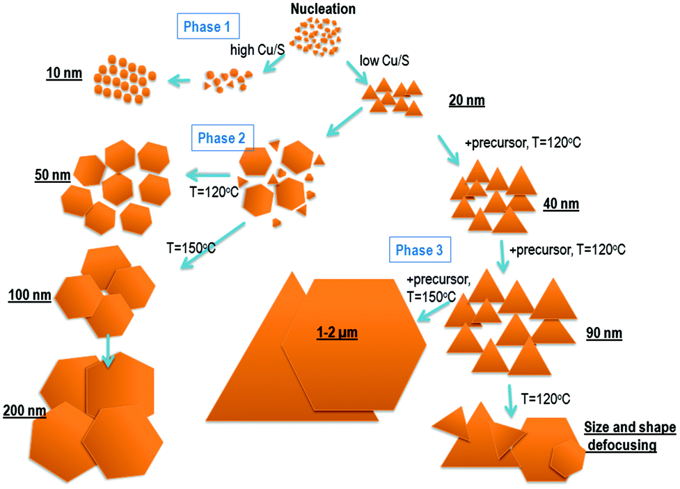
We employed the hot-injection approach of Wu et al.12 where the S–OAm mixture is introduced to the copper(I) precursor (CuI) in OAm at moderate temperatures without any further co-ligands. For the thickness adjustment, we employed a DPE/OAm mixture as the solvent. To understand the role of the iodide in the synthesis coming from the precursor, we performed halogen-free reactions based on copper acetate and copper oleate as precursors alternatively to the CuI-based synthesis.The balance of the reactivity of participating components plays an important role.43,44 In our case, the copper cation being a soft Lewis acid should be appropriately coordinated by certain soft Lewis bases (iodide anions) to provide sufficiently low reactivity compared to elemental sulfur in OAm in order to form stoichiometric Cu1S. Although the stoichiometric window for the formation of the pure covellite phase is rather narrow, we were able to study the influence of the Cu:S ratio on the morphology of the nanostructures taking several intermediate aliquots during the synthesis procedure.
Starting with a 0.8:1 (Cu:S) ratio, we observe the nucleation of irregular round covellite nanodisks which slowly ripen retaining the shape (Fig. 1A and B; the corresponding XRD pattern is shown in Fig. 1C). Few triangular platelets are also observed. When the Cu:S ratio is decreased to 0.4:1, the triangular shape fraction increases (Fig. 1D). Under these conditions, the system typically undergoes three phases shown in Fig. 1D–I: (1) nucleation (phase 1, kinetic growth mode); (2) size-shape-transformation phase, characterized by thermodynamic growth and ripening; (3) anisotropic growth at elevated temperatures.
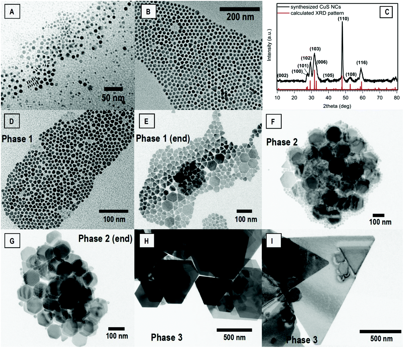 | ||
| Fig. 1 Temporal evolution of the CuxS 2D system at different Cu:S precursor ratios: (A,B) 0.8:1 (1 min, 60 min); (C) XRD pattern of CuxS NCs. Reference: calculated profile based on the crystal structure for covellite from ref. 46; (D,E,F,G) 0.4:1 (1 min, 30 min, 60 min, 120 min). Reaction temperature 120 °C; (H,I) growth at elevated temperature with precursor addition (160 °C for 60 min and 150 °C for 16 h DPE:OAm 1:1 v/v). | ||
During this process, in the first phase, the initial nanoparticles crystallize in irregular shapes with a tendency to form triangles followed by anisotropic growth and shape focusing (phase 1, start), observed also by Hsu et al.40 for a CuS one-pot synthesis. In parallel, we observe the growth of hexagonal platelets despite the presence of halogen ions (iodide) in the flask. With proceeding reaction time (5–120 minutes), the monomer supply rate for the growth decreases and further ripening occurs at the expense of smaller triangles, which start to dissolve (Fig. 1D–G). Hexagonal particles ripen further while full dissolution of smaller ones takes place. Eventually, the growth of hexagonal nanoprisms reaches saturation and stops. Monitoring of the synthesis revealed the ability of CuS NCs to grow anisotropically to nanosheets with 1–2 micron lateral size at elevated temperatures in the range of 140–180 °C, if an additional amount of precursors is supplied to the flask like it was shown for CdSe nanoplatelets.45 The micron-sized CuS NSs possess thicknesses of about 10 to 40 nm depending on the synthesis conditions (see ESI, Fig. S1† for the AFM image). The XRD pattern of the as-prepared CuxS NCs can be found in Fig. 1C. XRD reflexes of different copper sulfide crystal phases appear at similar values, and some of them coincide like in the case of covellite, yarrowite, talnakhite and digenite, for example. However, the covellite phase can be distinguished by the simultaneous appearance of peculiar reflexes at 10° (002), 27.2° (100), 27.7° (101), 39.5° (102) and 48° (110). In general, the observed XRD patterns match the hexagonal structure of covellite well and exclude the presence of other phases (see Fig. S2† for the XRD of different shapes of CuS). The intensity of the reflexes for 2D NCs is influenced by the preferential orientation of nanoprisms on the substrate and will be discussed later in this section.
We noticed that a further decrease of the Cu:S ratio promotes the formation and growth of faceted triangles with sizes in the range between 30 and 50 nm (Fig. 2) and thicknesses of approximately 3 to 5 nm (Fig. S2B†). This indicates that the formation of triangles is determined by two factors – a kinetic mode of growth and balancing of the reactivity of Cu and S (synthesis under sulfur excess).
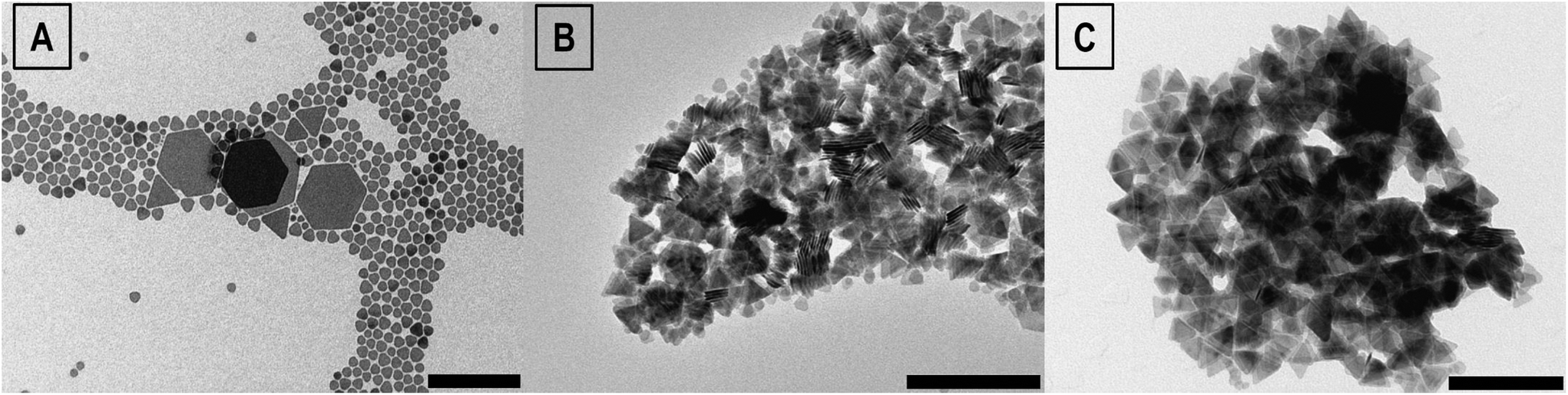 | ||
| Fig. 2 TEM images of CuS NCs after 5 min of synthesis at 120 °C with Cu:S ratios 0.4:1 (A), 0.2:1 (B) and 0.1:1 (C). Scale bar 200 nm. | ||
One of the additional factors for the shape control is the amount of non-coordinating solvent (e.g. DPE), introduced to the synthesis in parallel to OAm. An increase of the overall amount of solvent promotes the nucleation of a smaller amount of bigger particles and allows retaining the system in the kinetic growth mode for a longer period due to higher available monomer buffer. Dilution of OAm with up to 50% of DPE provides an advantage for monomers coming to the surface of NCs in competition with OAm. Thus, triangular NCs can be observed as the dominant shape with lateral dimensions even up to 200 nm upon addition of monomers using a syringe pump (ESI, Fig. S3†).
The influence of halogens on the shape of NCs has been frequently reported both for semiconductors,47–51 in particular for copper sulfide,40,41 and for metals.52,53 In many cases, halogens selectively adsorb on specific facets promoting shape transformation.48,54 In our case, although the copper/iodide ratios were identical in all of the above-mentioned syntheses, the halogen ions could have some impact on the shape of NCs. We studied the structure of the synthesized NCs by selected-area electron diffraction (SAED). We synthesized triangular and hexagonal nanosheets in the submicron range and studied the SAED patterns of individual particles to assign the crystalline orientation with respect to their shape. By exposing the sheets from the [001] zone axis with an electron beam, we were able to assign the side facets of the triangular NCs to (100), (010) and (1![[1 with combining macron]](https://www.rsc.org/images/entities/char_0031_0304.gif) 0), which have identical atomic cross-sections and thus equal surface energies (Fig. 3) similar to the observations of Du et al.39 This feature follows from the symmetry of the crystal which belongs to the P63/mmc space group. The appearance of the hexagonal shape is conjugated with the development of a facet between (010) and (100) which is (10) (Fig. 3). It follows that all side facets of a CuS hexagonal NS are identical in their structure and stoichiometry and that they are either copper-rich or sulfur terminated. This excludes the scenario of preferred lateral growth by selective passivation, since all six directions are energetically equivalent. Since at the end of the syntheses we get regular triangles, truncated triangles or regular hexagons, in general regular or symmetric shapes as our major morphological product, we can assume that in phase 1 exactly triangles are the initial faceted shape as a basis, and during the ripening process, they develop into truncated triangles and hexagons.
0), which have identical atomic cross-sections and thus equal surface energies (Fig. 3) similar to the observations of Du et al.39 This feature follows from the symmetry of the crystal which belongs to the P63/mmc space group. The appearance of the hexagonal shape is conjugated with the development of a facet between (010) and (100) which is (10) (Fig. 3). It follows that all side facets of a CuS hexagonal NS are identical in their structure and stoichiometry and that they are either copper-rich or sulfur terminated. This excludes the scenario of preferred lateral growth by selective passivation, since all six directions are energetically equivalent. Since at the end of the syntheses we get regular triangles, truncated triangles or regular hexagons, in general regular or symmetric shapes as our major morphological product, we can assume that in phase 1 exactly triangles are the initial faceted shape as a basis, and during the ripening process, they develop into truncated triangles and hexagons.
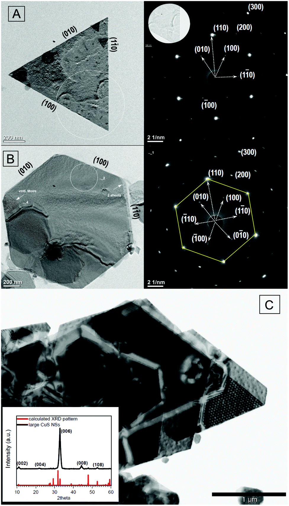 | ||
| Fig. 3 TEM image of large CuS NSs and the SAED pattern with the [001] zone axis: (A) triangular NS; (B) hexangular NSs. Study of SAED patterns reveals the (100), (010), (10) facets of CuS NSs. Overlapping hexagonal NSs cause the Moiré pattern; (C) truncated triangular and hexangular NSs. Inset: XRD patterns of large NSs on the substrate. The textural effect influences the intensity distribution, (00l) reflexes become dominant, whereby the intensity of the (101), (102) and (103) reflexes drastically decreases. According to the Scherrer equation, the average thickness was found to be about 9.6 nm. | ||
The appearance of triangles during the hot-injection synthesis is not trivial to interpret and could be rationalized by the fact that during the first few moments of the precursor mixing the local concentration of copper cations and especially sulfur (which is injected) is at its maximum ensuring prompt nucleation and growth in the kinetic regime. During the growth of NCs, OAm as the solvent and ligand passivates the copper surface cations due to the nucleophilic character of the amine group. We simulate the interaction of the amine and carboxylic groups with different facets using a DFT-based approach. In particular, we see that the adsorption energy for the Cu-rich (100) facet is essentially larger than that for (110) (Table 1). As a consequence, the (100) facets grow slower. This difference constitutes the growth of facets in triangles and hexagons with (100)-like edge facets. Atomistic 3D models for CuS NCs are presented in Fig. 4A and B.
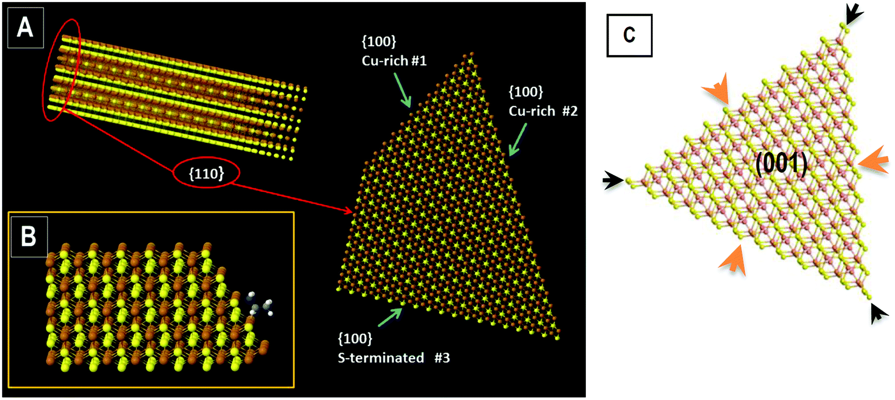 | ||
| Fig. 4 Scaled-down atomic models for CuS NCs terminated with different facets: (A) faceting of the CuS NC according to the simulated surfaces (Table 1); (B) exemplarily shown amine group adsorbed at the {100} facet (#2) (simulation); (C) triangular CuS NC terminated at edges with sulfur atoms, vertex and central positions are denoted by arrows. The lateral crystal plane corresponds to the (001) facet. | ||
| Adsorption energy, eV | ||||
|---|---|---|---|---|
| {100} #1 (Cu-rich) | {100} #2 (Cu-rich) | {100} #3 (S-terminated) | {110} | |
| C2 alkylamine (CH3–CH2–NH2) | 1.66 | 2.61 | 0.67 | 1.73 |
| Acetate (CH3COO−) | 4.82 | 6.4 | 2.58 | 3.19 |
Another important observation from the simulation results is the large difference of the OAm adsorption energy for Cu- and S-rich ionic cross-sections of the same (100) facet. For the S-terminated (100) facet, the adsorption energy is nearly 2.5 to 3.9 times smaller than that for the Cu-rich atomic cross-section (options #1 and #2 compared to option #3 from Table 1). Hence, the Cu-rich facet passivated by OAm represents a large potential barrier for the [CuS]x monomer's access and hampers the growth. Obviously, an excessive amount of S-precursor in the solution in comparison with the Cu-precursor promotes the addition of monomers and further growth in the kinetic mode facilitating the formation of triangles.
We assume that the most reactive sites are the vertex (tip) positions of the triangular NC, and under a sufficient supply of sulfur, these positions are occupied, promoting the triangular shape of the initial NCs. Considering phase 1 occurs in a kinetic (non-equilibrium) regime, the growth is accompanied by the maximization of the surface area. After a certain period when the monomer solution is depleted, the growth changes to the thermodynamic mode. Under equilibrated monomer supply some particles grow and develop all six facets to minimize the surface energy of the system at the expense of smaller triangles which slowly dissolve. Sharp tips dissolve first having the largest radius of curvature and being less stable in comparison with the edge according to the Ostwald ripening process.55 The role of sulfur anions can be compared with the role of a surface passivator for Cu-rich facets, which competes with OAm, promoting the observed crystal growth.
The atomic structure of triangular NCs is presented in Fig. 4C. The reaction of monomers at positions near and at the vertex (least stable, black arrows) is the vital process for retaining the triangular shape and a sufficient monomer supply rate is of great importance here. During phase 2 when the monomer supply drops substantially, the growth rate over the perimeter of the triangular NCs becomes non-homogeneous. Monomers which condense at side facets obviously occupy either central positions of the edge (Fig. 4C, orange arrows) allowing the development of other three facets from the corner (leading to truncated triangles and hexagons).
To better understand the shape transformation of CuS nanoprisms under different conditions, we investigated the halogen-free reaction, where CuI is substituted with copper acetate. For comparison, the synthesis with copper oleate is also studied, where to the reaction flask with copper acetate the corresponding amount of oleic acid was added. Under vacuum (2 h) and moderate heating (80 °C), acetate can be transferred to oleate which has been already shown to increase the reactivity of lead cations.49 The TEM images of two representative routes are shown in Fig. 5. Triangular and hexangular nanoprisms in this protocol adopt the same crystal orientation with respect to the shape shown by HRTEM analysis (Fig. S4†).
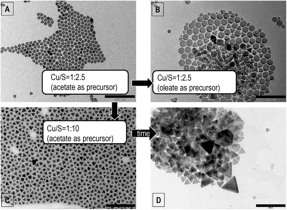 | ||
| Fig. 5 Shape changes of CuxS NCs during hot-injection synthesis in OAm. (A,B,C) TEM images of samples after 1 min synthesis; (D) after 5 minutes. (A,B) Cu:S ratio 0.4:1, (C) 0.1:1. Preparation of faceted triangles (picture C) with an average side length of 20 nm (σ = 19%). The size increased with time to ∼50 nm (D). Scale bars 200 nm. | ||
During phase 1 in the halogen-free synthesis, the particles still tend to adopt the triangular shape (Fig. 5A). However, some irregular and hexagonal shapes are also observed as a minor fraction. The short acetate group still binds strongly to the copper ions, reducing its reactivity. Transfer to the copper oleate precursor increases the reactivity of the metal. By keeping other conditions constant, we observe the adoption of both hexagonal (dominant) and triangular shapes after 1 minute after the injection of sulfur (Fig. 5B). After 60 minutes of synthesis, CuxS nanoprisms typically transform into polygonal particles with an average diameter of 63 nm (dispersity D = 15%). The addition of precursors during phase 2 can increase this size up to 250 nm (not shown here).
If the amount of copper is reduced to a Cu:S ratio of 0.1:1 only triangles with sharp vertices are formed in the acetate-based synthesis (Fig. 5C) with an average size of 20 nm (D = 19%). During the first 5 minutes, the triangles retain their shape and can grow up to a lateral size of 50 nm (D = 12%); however, a minor fraction of bigger triangles is present (around 100 nm). After 5 minutes, the system reaches phase 2, where size and shape transformations lead to hexagonally shaped ripened particles. If we keep the system in phase 1 (kinetic growth) by drop-wise addition of monomers with a predefined Cu:S ratio, the triangular shape will be dominant even after 60 minutes of synthesis (Fig. S5†).
The generalized mechanism for our colloidal 2D CuS growth is illustrated in the scheme in Fig. 6. It should be noted that the presence of the acetate group on the surface after the nucleation of CuS NCs might also have an impact on the shape of NCs with respect to their crystallographic orientation. However, simulations show that the adsorption energy of acetate obeys a similar tendency like the amine group: the binding affinity to the Cu-rich (100) facet is at least twice higher than that for the (20) facet implying the preferential growth of edges along the {100}-like facets and not along the {20}-like facets. Due to the fact that OAm is the solvent in the system, the gradual exchange of acetate to OAm on the NC's surface is expected according to the law of mass action.
 | ||
| Fig. 6 Scheme of the shape transformations during the OAm–S based hot-injection CuxS synthesis depicting ways to control the shape. Blue arrows denote time flow. | ||
Shape control for copper sulfides was demonstrated and discussed by van der Stam et al. for digenite41 and by Hsu et al.40 for covellite phases of copper sulfide. In the case of the rare tetragonal digenite crystal structure, the mechanism of shape transformation in fact might be based on the selective passivation of specific facets by TOPO. However, in the covellite case, as shown above, this possibility is restricted due to the symmetry of the crystal, and the detailed mechanism of the influence of halogens is still a challenge. However, the control over the shape for covellite can be better understood in the framework of (un)balancing the reactivities of the copper and sulfur monomers demonstrated above. Halogens are distinct nucleophiles, able to bond Cu+ cations and thus, reducing the metal reactivity and shifting the balance towards sulfur. This promotes focusing of the shape to the triangular one, where halogens serve as mediators of the process.
Optical properties of CuS nanoprisms in the NIR region
The demonstrated synthetic tunability of the shape and size of CuS nanoprisms provides broad possibilities for the optical absorption control in the NIR region. Several earlier studies reported on the measurements and simulations of extinction spectra for CuS NCs.9,19,56 However, the analysis for the triangular shape of CuS is still missing. In this section, we report on the optical features of 2D CuS nanoprisms with a specific shape and compare them with the experimental ones. We perform our study based on the assumption that the optical properties of the covellite phase in the NIR region can be precisely modelled in the framework of the Drude–Sommerfeld theory. The intrinsic metallic nature of covellite shown by ab initio simulations32 allows one to construct the complex dielectric function according to the known relation (1) and to simulate the plasmon resonance conditions for these particles: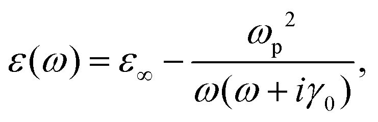 | (1) |
Fig. 7A shows the spectral response of the CuS NCs to the shape transformations during synthesis phases 1 and 2 (curves 1–4). In the UV-VIS region, the fundamental absorption can be found below 600 nm which hardly depends on the size of particles and shows the relatively large value of the optical band gap of the synthesized material (over 2.1 eV, suggesting the covellite phase to be in confinement4,59). The NIR region shows distinct spectral features (LSPR resonances) essentially sensitive to shape and size changes. Initially we form triangles and allow them to grow without precursor addition in the non-kinetic mode (Fig. 6, phase 2). As discussed above, the system goes through the dissolution of smaller triangles (first of all – tips) and the formation of larger hexagonal NSs (see Fig. 1D–G). This can be exactly tracked by the absorption spectra for different temporal aliquots. The NIR spectrum for the aliquot with a major morphological yield in triangular shape (average side length of 28 nm with 4.6 nm average thickness) contains an intense broad nonsymmetrical peak centered at 1650 nm with shoulder(s) at the short-wavelength side in the 800–1200 nm range, which is typical of a triangular nanoprism localized surface plasmon resonance (LSPR) spectrum (see simulation section, Fig. 7D). When the system goes through size and shape defocusing, the tips of triangles dissolve, giving rise to a rounded shape. Therefore, the main peak shifts to shorter wavelengths becoming narrower and more symmetric. This corresponds to the spectrum of thin nanodisks shown further in Fig. 7D. At the same time, large hexagonal NSs form due to the equilibrated slow growth, giving rise to absorption at longer wavelengths, which correspondingly can be observed in the obtained spectrum (Fig. 7A, curve 3). Eventually small particles completely dissolve and the narrow plasmon resonance peak vanishes. For larger hexagonal NSs, the main (in-plane dipolar) resonance shifts further to longer wavelengths, which can also be seen in the simulations in Fig. 7D and the spectrum in the range 1–2.5 μm contains only higher and out-of-plane modes60 between 0.85 and 2 μm.
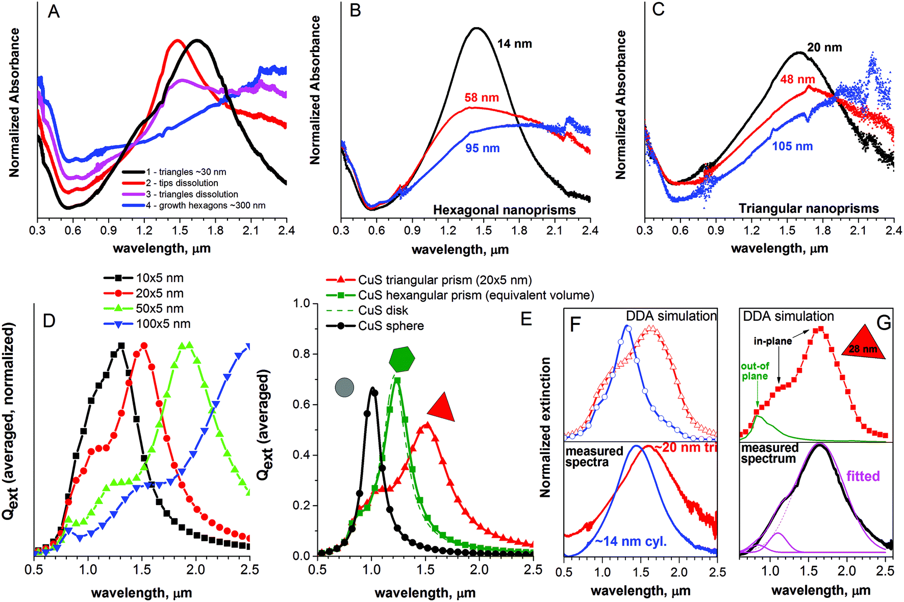 | ||
| Fig. 7 UV-VIS-NIR spectroscopic characterization of the synthesized CuS NCs supported by DDA simulations: (A) temporal evolution of the absorption spectrum of CuS NCs during the synthesis through size and shape transformations described in the main text. Primarily, small triangular nanoprisms of ∼30 nm appear (curve 1), with subsequent dissolution of the tips (curve 2) and dissolution of former triangles (curve 3) during the growth of large hexagonal NSs in non-kinetic mode and start to dominate; finally, only the large hexagonal NSs (∼300 nm) remain in the product of the reaction (curve 4). Simulated by the DDA method, the spectra for these particles are presented below in (D) and (E). (B) Absorption spectra of quasi-hexagonal nanoprisms (rounded side facets) prepared separately with sizes between 13 and 95 nm. (C) Absorption spectra of triangular nanoprisms (20–105 nm). (D–E) Simulated extinction spectra of CuS NCs with different shapes and sizes. Here, the results were averaged over 15 spatial orientations (ωp = 4.4 eV, ε∞ = 8.0, γ0 = 0.2). (D) Triangular nanoprisms with an edge length of 10, 20, 50 and 100 nm and a thickness of 5 nm. (E) Comparison of the extinction spectra of the triangular prism (edge 20 nm, thickness 5 nm) with the hexagonal prism (thickness 5 nm), disk (thickness 5 nm) and sphere of CuS with equivalent volume (15600 dipols). (F) Comparison of the measured LSPR peak of the smallest CuS NCs (disks, base diameter 14 nm, thickness 4 nm and triangles 20 × 4 nm) with a simulated spectrum in the NIR region. (G) Comparison of the measured LSPR peak (black curve) with the simulated one (red) for 28 × 4.6 nm triangular nanoprisms with the assignment of out-of-plane resonance (green curve) and the corresponding mathematical fitting of the experimental spectrum with three Gaussian curves centered at resonance positions found by the simulations (pink curves). | ||
Applying synthetic procedures according to the scheme in Fig. 6 allows separately producing triangular and quasi-hexangular CuS nanoprisms with a controlled size in the range of about 13–100 nm (Fig. S6†). The corresponding absorption spectra are displayed in Fig. 7B, C (additionally Fig. S7†) for the set of triangles and hexagon-like nanoprisms of CuS. These spectra contain similar features and demonstrate the same trends with respect to shape and size compared to our simulations (Fig. 7D–F). From our simulations we see that the extinction spectra of equivalent volume hexagonal, cylindrical and triangular NCs differ qualitatively and quantitatively. The peak of LSPR for spherical NCs is blue-shifted and contains one single resonance; therefore, the peak is symmetric and narrow. Triangular NCs show more resonances which are successfully resolved by spectroscopy as well. In particular, the main peak is non-symmetric with shoulder(s) at shorter wavelengths, hence it is much broader. Hexangular NCs show spectral peaks between those of spherical and triangular NCs with a shoulder at short wavelengths (Fig. 7E).
We note that LSPR-induced absorption of the synthesized CuS NCs covers a broad range of the NIR spectral region demonstrating huge potential for applications in catalysis, NIR energy harvesting and transfer. Furthermore, the crystallization of CuS in a triangular shape theoretically gives the additional possibility to induce a substantial E-field enhancement on the tips due to the increased surface curvature.61,62 In Fig. 8A, we visualize the electric field intensity |E|2 normalized to the incident electric field intensity (near-field mapping) for CuS nanoprisms of different shapes. In an ideal case, when the tip is sharp, the triangular shape allows the field intensity to be increased by a factor of 1400 to 2450 at the hot spots for the normal incidence (with respect to the lateral surface) of linearly polarized radiation. The corresponding visualization for hexagonal nanoprisms and disks with an equivalent volume is shown in Fig. S8.† Maximal local field intensity enhancement averaged over 75 spatial orientations of the target reached a factor of 37, 67 and 249 for disks, hexagonal and triangular prisms of equivalent volume correspondingly, making the triangular shape particularly attractive with respect to non-linear processes and energy transfer.
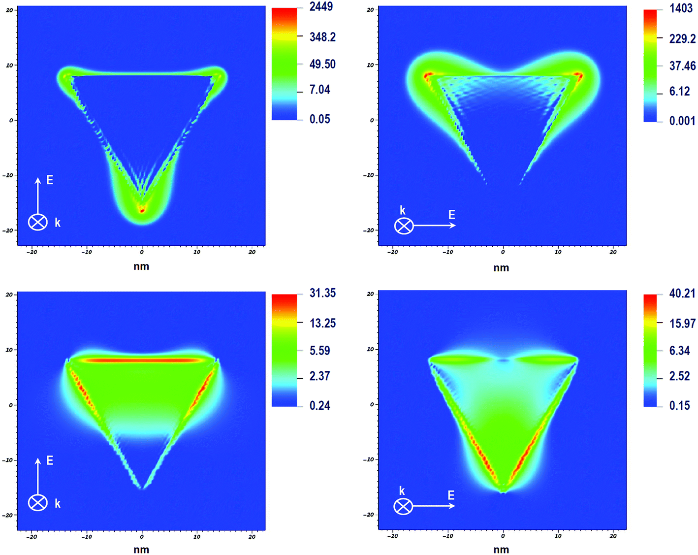 | ||
| Fig. 8 Visualization of the near-field intensity (|E|2/|E0|2) in triangular CuS nanoprisms. The orientation of k- and E-vectors is denoted in the images. (A,B) In-plane intensity distribution at 1650 nm (dipolar LSPR mode). (C,D) In-plane intensity distribution at 1020 nm (quadrupolar LSPR mode). Because of the very high spatial field concentration at 1650 nm, a logarithmic color scaling has been applied. | ||
To assign the resonant features in the absorption spectrum exemplarily shown for triangular CuS nanoprisms in Fig. 7G, we simulate the interaction of NCs with NIR radiation with different spatial orientations of the NCs, inducing separate out-of-plane and in-plane modes. We also map the E-field intensity at different wavelengths for the qualitative assessment of the oscillating mode. The main measured LSPR resonance of 28 nm large CuS nanoprisms is situated at 1650 nm and can be attributed to the dipolar in-plane mode due to the highest intensity and sensitivity to lateral dimensions. From the simulations, it is recognizable that triangular CuS nanoprisms can produce additional resonances on the short-wavelength side of the main plasmon peak (situated around 1120 nm and 830 nm). If the polarization of the incident radiation excites only the out-of-plane resonance (incident polarization of the E-field was set orthogonally to the lateral base surface), merely a broad peak at 830 nm appears (green curve in Fig. 7G) which becomes smeared out after the averaging procedure. This peak should be attributed to the out-of-plane LSPR resonance mode. We also note that this peak hardly shifts when the lateral size of particles increases drastically. Simulations with values of ωp = 4.4, ε∞ = 8.0 and γ0 = 0.2 show an additional weak out-of-plane peak (see the green curve in Fig. 7G) on the longer wavelength side around 1025 nm. According to previous studies with silver nanoprisms and gold nanorods,63–66 the quadrupole mode appears at higher frequencies in comparison with the dipolar one, hence we can attribute the peak at 1025 nm to the dipolar out-of-plane resonance, and the peak at 830 nm to the quadrupole out-of-plane LSPR mode. We conclude that other peaks at 1120 nm and 1650 nm should be attributed to the in-plane modes. The intensity mapping of the electric field is shown in Fig. 8 for different wavelengths and polarizations of incident light on the triangular prism. The most intense peak of the spectrum of this NC (1650 nm) in the planar slice produces the field distribution which is inherent to the dipole resonant oscillations, showing a point-like field enhancement exactly at the tips. In contrast to this, the intensity distribution for the 1120 nm radiation appears at the sides of the NC allowing us to conclude about the quadrupole mode of the in-plane resonance. Hence, these modes should be sensitive to the lateral dimensions of the NC. In fact, we see the red-shift of the shoulder in the measured and simulated spectra. Using the values of the LSPR positions from our simulations, we satisfactorily reproduce the observed spectrum with three Gaussian curves (Fig. 7G, pink curves) centered at 840, 1100 and 1650 nm. As nimbly noted by Xie et al.,19 the out-of-plane modes can be additionally influenced (dampened) by the anisotropic conductivity of covellite,24 causing less intense red-shifted resonance in the spectrum in comparison with the one predicted by the model. For smaller CuS NCs (13–20 nm, Fig. 7F), we find that the best fit of the theoretical spectra can be performed when the plasmon frequency is reduced to 4.0 eV, with γ0 = 0.25. This can be rationalized by the fact that these particles have a higher surface-to-volume ratio. A larger amount of surface interaction (oxidation) and defects will reduce the effective concentration of free holes and induce the red-shift and slight broadening of the LSPR peak.
It is worth noting that the position of the LSPR peak is governed by several factors, besides the geometry of the NCs. First, it is directly dependent on the plasma frequency which in turn is defined by the concentration of free carriers in the materials and the effective mass. Respectively, the surface chemistry, surface defects and minor shifts of the stoichiometry of the NC can essentially influence the effective free carrier concentration in the particle.30 Secondly, the mutual arrangement of particles during the measurement can cause an essential red-shift of the LSPR peak in the case of side-to-side stacking or the peak broadening and damping in the case of sandwich-stacking.56 Eventually, the solvent dielectric constant plays an important role for the LSPR peak position as well. In our case, the copper sulfide NCs synthesized from iodide and acetate precursors in OAm possess a covellite crystal structure and in general they show a slightly shifted LSPR resonance to longer wavelengths in comparison with the ones reported by e.g. Tao et al. or Xie et al.19,40 However, the general features and NIR spectral trends of the system indicate the metallic character of the synthesized NCs (which can be true only for stoichiometric CuS) and the observed differences can be explained by the above-mentioned complex factors influencing the LSPR.
Conclusions
We describe a straightforward and flexible shape control over copper sulfide nanocrystals (covellite) by balancing the precursors’ reactivity and the choice of the growth regime. In our approach, we do not use additional ligands keeping the surface of the particles in its native state which comes from the synthesis conditions. We present a scheme for one-pot synthesis which provides the possibility to produce triangle and hexagonal-like 2D nanocrystals in a controllable way in the size range between 13 and 100 nm. We show also the possibility to grow CuS nanoprisms to micron-sized nanosheets with thicknesses of 20 nm. The main factors for the shape control and shape transformation are precursor concentrations and their ratio, temperature, time and the growth mode. By means of TEM imaging, selected area electron diffraction and DFT simulations, we explain the reasons for the distinct crystallographic orientations with respect to the shape of the CuS NCs and we rationalize the importance of the sulfur-source excess during the synthesis of NCs in oleylamine for the triangular shape. Additionally, we analyze the absorption spectra in the NIR region with the help of DDA simulations and we show the influence of the shape of CuS nanoprisms on LSPR features. We confirm that the NIR optical properties of our system (intense plasmon resonance, its dependence on the geometry of the NC) can be well described by the Drude–Sommerfeld theory for metals. From our calculations, we demonstrate the huge potential of triangular CuS nanoprisms for spatial and spectral electric field concentration on the tips of the NCs in the NIR region that can serve as an important material for enhanced catalytic and non-linear effects.Conflicts of interest
There are no conflicts to declare.Acknowledgements
A. Kornowski, D. Weinert (HRTEM), A. Barck (XRD), L. Heymann, Dr V. Lesnyak, Dr C. Strelow, P. Witthöft and F. Li are acknowledged for useful discussions. The authors gratefully acknowledge the financial support of the European Research Council via the ERC Starting Grant “2D-SYNETRA” (Seventh Framework Program FP7, Project: 304980). C.K. thanks the German Research Foundation DFG for financial support in the frame of the Cluster of Excellence “Center of ultrafast imaging CUI” and the Heisenberg scholarship KL 1453/9-2.References
- D. Feucht, Heterojunctions in photovoltaic devices, J. Vac. Sci. Technol., 1977, 14(1), 57–64 CrossRef CAS.
- H. Pathan, J. Desai and C. Lokhande, Modified chemical deposition and physico-chemical properties of copper sulphide (Cu2S) thin films, Appl. Surf. Sci., 2002, 202(1–2), 47–56 CrossRef CAS.
- Y. Rodriguez-Lazcano, et al., Properties of CuS thin films treated in air plasma, Thin Solid Films, 2009, 517(21), 5951–5955 CrossRef CAS.
- A. Raevskaya, et al., Catalytic activity of CuS nanoparticles in hydrosulfide ions air oxidation, J. Mol. Catal. A: Chem., 2004, 212(1–2), 259–265 CrossRef CAS.
- L. Partain, et al., Degradation of a Cu x S/CdS solar cell in hot, moist air and recovery in hydrogen and air, J. Appl. Phys., 1983, 54(11), 6708–6720 CrossRef CAS.
- W. Bryks, et al., Supramolecular precursors for the synthesis of anisotropic Cu2S nanocrystals, J. Am. Chem. Soc., 2014, 136(17), 6175–6178 CrossRef CAS PubMed.
- Y. Wu, et al., Synthesis and photovoltaic application of copper(I) sulfide nanocrystals, Nano Lett., 2008, 8(8), 2551–2555 CrossRef CAS PubMed.
- Y.-Q. Liu, et al., Facile microwave-assisted synthesis of klockmannite CuSe nanosheets and their exceptional electrical properties, Sci. Rep., 2014, 4, 5998 CrossRef CAS PubMed.
- Y. Zhao, et al., Plasmonic Cu2−x S nanocrystals: optical and structural properties of copper-deficient copper(I) sulfides, J. Am. Chem. Soc., 2009, 131(12), 4253–4261 CrossRef CAS PubMed.
- M. Page, et al., Copper sulfide as a light absorber in wet-chemical synthesized extremely thin absorber (ETA) solar cells, Energy Environ. Sci., 2009, 2(2), 220–223 RSC.
- S. Vikulov, et al., Fully Solution-Processed Conductive Films Based on Colloidal Copper Selenide Nanosheets for Flexible Electronics, Adv. Funct. Mater., 2016, 26(21), 3670–3677 CrossRef CAS.
- X. J. Wu, et al., Copper-Based Ternary and Quaternary Semiconductor Nanoplates: Templated Synthesis, Characterization, and Photoelectrochemical Properties, Angew. Chem., Int. Ed., 2014, 53(34), 8929–8933 CrossRef CAS PubMed.
- X. J. Wu, et al., Two-dimensional CuSe nanosheets with microscale lateral size: Synthesis and template-assisted phase transformation, Angew. Chem., 2014, 126(20), 5183–5187 CrossRef.
- H. Lee, et al., In situ growth of copper sulfide nanocrystals on multiwalled carbon nanotubes and their application as novel solar cell and amperometric glucose sensor materials, Nano Lett., 2007, 7(3), 778–784 CrossRef CAS PubMed.
- S. S. Kalanur, S. Y. Chae and O. S. Joo, Transparent Cu 1.8 S and CuS thin films on FTO as efficient counter electrode for quantum dot solar cells, Electrochim. Acta, 2013, 103, 91–95 CrossRef CAS.
- C.-H. Lai, et al., Direct growth of high-rate capability and high capacity copper sulfide nanowire array cathodes for lithium-ion batteries, J. Mater. Chem., 2010, 20(32), 6638–6645 RSC.
- C. M. Hessel, et al., Copper selenide nanocrystals for photothermal therapy, Nano Lett., 2011, 11(6), 2560–2566 CrossRef CAS PubMed.
- A. Wolf, T. Kodanek and D. Dorfs, Tuning the LSPR in copper chalcogenide nanoparticles by cation intercalation, cation exchange and metal growth, Nanoscale, 2015, 7(46), 19519–19527 RSC.
- Y. Xie, et al., Metallic-like stoichiometric copper sulfide nanocrystals: phase-and shape-selective synthesis, near-infrared surface plasmon resonance properties, and their modeling, ACS Nano, 2013, 7(8), 7352–7369 CrossRef CAS PubMed.
- S.-W. Hsu, W. Bryks and A. R. Tao, Effects of Carrier Density and Shape on the Localized Surface Plasmon Resonances of Cu2–x S Nanodisks, Chem. Mater., 2012, 24(19), 3765–3771 CrossRef CAS.
- S.-W. Hsu, K. On and A. R. Tao, Localized surface plasmon resonances of anisotropic semiconductor nanocrystals, J. Am. Chem. Soc., 2011, 133(47), 19072–19075 CrossRef CAS PubMed.
- J. A. Faucheaux, A. L. Stanton and P. K. Jain, Plasmon resonances of semiconductor nanocrystals: physical principles and new opportunities, J. Phys. Chem. Lett., 2014, 5(6), 976–985 CrossRef CAS PubMed.
- A. C. Berends, et al., Formation of colloidal copper indium sulfide nanosheets by two-dimensional self-organization, Chem. Mater., 2017, 29(24), 10551–10560 CrossRef CAS PubMed.
- W. Liang and M.-H. Whangbo, Conductivity anisotropy and structural phase transition in covellite CuS, Solid State Commun., 1993, 85(5), 405–408 CrossRef CAS.
- P. Kumar, R. Nagarajan and R. Sarangi, Quantitative X-ray absorption and emission spectroscopies: electronic structure elucidation of Cu 2S and CuS, J. Mater. Chem. C, 2013, 1(13), 2448–2454 RSC.
- H. Nozaki, K. Shibata and N. Ohhashi, Metallic hole conduction in CuS, J. Solid State Chem., 1991, 91(2), 306–311 CrossRef CAS.
- J. M. Luther, et al., Localized surface plasmon resonances arising from free carriers in doped quantum dots, Nat. Mater., 2011, 10(5), 361 CrossRef CAS PubMed.
- C.-L. Tsai, J.-C. Chen and W.-J. Wang, Near-infrared absorption property of biological soft tissue constituents, J. Med. Electron. Biol., 2001, 21(1), 7–14 Search PubMed.
- H. Nishi, K. Asami and T. Tatsuma, CuS nanoplates for LSPR sensing in the second biological optical window, Opt. Mater. Express, 2016, 6(4), 1043–1048 CrossRef CAS.
- O. A. Balitskii, et al., Tuning the Localized Surface Plasmon Resonance in Cu2–x Se Nanocrystals by Postsynthetic Ligand Exchange, ACS Appl. Mater. Interfaces, 2014, 6(20), 17770–17775 CrossRef CAS PubMed.
- V. B. Llorente, et al., Electrochemical Tuning of Localized Surface Plasmon Resonance in Copper Chalcogenide Nanocrystals, J. Phys. Chem. C, 2017, 121(33), 18244–18253 CrossRef CAS.
- A. Morales-García, et al., First-principles calculations and electron density topological analysis of covellite (CuS), J. Phys. Chem. A, 2014, 118(31), 5823–5831 CrossRef PubMed.
- K. M. Rosso and M. Hochella Jr., A UHV STM/STS and ab initio investigation of covellite {001} surfaces, Surf. Sci., 1999, 423(2–3), 364–374 CrossRef CAS.
- M. Rang, et al., Optical near-field mapping of plasmonic nanoprisms, Nano Lett., 2008, 8(10), 3357–3363 CrossRef CAS PubMed.
- J. Nelayah, et al., Mapping surface plasmons on a single metallic nanoparticle, Nat. Phys., 2007, 3(5), 348 Search PubMed.
- A. F. Koenderink, Single-photon nanoantennas, ACS Photonics, 2017, 4(4), 710–722 Search PubMed.
- B. C. Marin, et al., Plasmon-enhanced two-photon absorption in photoluminescent semiconductor nanocrystals, ACS Photonics, 2016, 3(4), 526–531 Search PubMed.
- R. Lesyuk, et al., Simulation study of environmentally friendly quantum-dot-based photovoltaic windows, J. Mater. Chem. C, 2017, 5(45), 11790–11797 RSC.
- W. Du, et al., Shape-Controlled Synthesis and Self-Assembly of Hexagonal Covellite (CuS) Nanoplatelets, Chem. – Eur. J., 2007, 13(11), 3241–3247 CrossRef CAS PubMed.
- S.-W. Hsu, et al., Shape Focusing During the Anisotropic Growth of CuS Triangular Nanoprisms, Chem. Mater., 2015, 27(14), 4957–4963 CrossRef CAS.
- W. van der Stam, et al., Solution-Processable Ultrathin Size-and Shape-Controlled Colloidal Cu2–x S Nanosheets, Chem. Mater., 2014, 27(1), 283–291 CrossRef.
- The CP2K developers group. CP2K is freely available from http://www.cp2k.org/.
- Y. Zou, D. Li and D. Yang, Shape and phase control of CdS nanocrystals using cationic surfactant in noninjection synthesis, Nanoscale Res. Lett., 2011, 6(1), 374 CrossRef PubMed.
- R. Xie, M. Rutherford and X. Peng, Formation of high-quality I− III− VI semiconductor nanocrystals by tuning relative reactivity of cationic precursors, J. Am. Chem. Soc., 2009, 131(15), 5691–5697 CrossRef CAS PubMed.
- S. Ithurria, G. Bousquet and B. Dubertret, Continuous transition from 3D to 1D confinement observed during the formation of CdSe nanoplatelets, J. Am. Chem. Soc., 2011, 133(9), 3070–3077 CrossRef CAS PubMed.
- H. Evans and J. Konnert, Crystal structure refinement of covellite, Am. Mineral., 1976, 61(9–10), 996–1000 CAS.
- K.-T. Yong, et al., Shape control of CdS nanocrystals in one-pot synthesis, J. Phys. Chem. C, 2007, 111(6), 2447–2458 CrossRef CAS.
- M. Meyns, et al., Shape evolution of CdSe nanoparticles controlled by halogen compounds, Chem. Mater., 2014, 26(5), 1813–1821 CrossRef CAS.
- C. Schliehe, et al., Ultrathin PbS sheets by two-dimensional oriented attachment, Science, 2010, 329(5991), 550–553 CrossRef CAS PubMed.
- T. Bielewicz, et al., From dots to stripes to sheets: shape control of lead sulfide nanostructures, Chem. Mater., 2015, 27(24), 8248–8254 CrossRef CAS.
- G. B. Bhandari, et al., Thickness-controlled synthesis of colloidal PbS nanosheets and their thickness-dependent energy gaps, Chem. Mater., 2014, 26(19), 5433–5436 CrossRef CAS.
- T. H. Ha, H.-J. Koo and B. H. Chung, Shape-controlled syntheses of gold nanoprisms and nanorods influenced by specific adsorption of halide ions, J. Phys. Chem. C, 2007, 111(3), 1123–1130 CrossRef CAS.
- X. Huang, et al., Freestanding palladium nanosheets with plasmonic and catalytic properties, Nat. Nanotechnol., 2011, 6(1), 28 CrossRef CAS PubMed.
- M. Saruyama, M. Kanehara and T. Teranishi, Drastic structural transformation of cadmium chalcogenide nanoparticles using chloride ions and surfactants, J. Am. Chem. Soc., 2010, 132(10), 3280–3282 CrossRef CAS PubMed.
- D. V. Talapin, et al., Evolution of an ensemble of nanoparticles in a colloidal solution: theoretical study, J. Phys. Chem. B, 2001, 105(49), 12278–12285 CrossRef CAS.
- S.-W. Hsu, C. Ngo and A. R. Tao, Tunable and directional plasmonic coupling within semiconductor nanodisk assemblies, Nano Lett., 2014, 14(5), 2372–2380 CrossRef CAS PubMed.
- B. T. Draine and P. J. Flatau, Discrete-dipole approximation for scattering calculations, J. Opt. Soc. Am. A, 1994, 11(4), 1491–1499 CrossRef.
- B. T. Draine and P. J. Flatau, User guide for the discrete dipole approximation code DDSCAT 7.3, arXiv preprint arXiv:1305.6497, 2013.
- F. Ghribi, et al., Study of CuS thin films for solar cell applications sputtered from nanoparticles synthesised by hydrothermal route, Energy Procedia, 2015, 84, 197–203 CrossRef CAS.
- K. L. Kelly, et al., The optical properties of metal nanoparticles: the influence of size, shape, and dielectric environment, J. Phys. Chem. B, 2003, 668–677 CrossRef CAS.
- W. Hermoso, et al., Triangular metal nanoprisms of Ag, Au, and Cu: modeling the influence of size, composition, and excitation wavelength on the optical properties, Chem. Phys., 2013, 423, 142–150 CrossRef CAS.
- R. Morarescu, et al., Exploiting the localized surface plasmon modes in gold triangular nanoparticles for sensing applications, J. Mater. Chem., 2012, 22(23), 11537–11542 RSC.
- N. Okada, et al., Linear and nonlinear optical response of silver nanoprisms: local electric fields of dipole and quadrupole plasmon resonances, J. Phys. Chem. B, 2004, 108(26), 8751–8755 CrossRef CAS.
- V. Myroshnychenko, et al., Modelling the optical response of gold nanoparticles, Chem. Soc. Rev., 2008, 37(9), 1792–1805 RSC.
- Y. Sun, B. Mayers and Y. Xia, Transformation of silver nanospheres into nanobelts and triangular nanoplates through a thermal process, Nano Lett., 2003, 3(5), 675–679 CrossRef CAS.
- R. Jin, et al., Photoinduced conversion of silver nanospheres to nanoprisms, Science, 2001, 294(5548), 1901–1903 CrossRef CAS PubMed.
Footnote |
| † Electronic supplementary information (ESI) available. See DOI: 10.1039/c8nr06738d |
| This journal is © The Royal Society of Chemistry 2018 |