
 Open Access Article
 This Open Access Article is licensed under a
 Creative Commons Attribution 3.0 Unported Licence
Highly active single-layer MoS2 catalysts synthesized by swift heavy ion irradiation†
Lukas
Madau߇
 a,
Ioannis
Zegkinoglou‡
b,
Henrique
Vázquez Muiños
c,
Yong-Wook
Choi
b,
Sebastian
Kunze
b,
Meng-Qiang
Zhao
d,
Carl H.
Naylor
d,
Philipp
Ernst
a,
Erik
Pollmann
a,
Oliver
Ochedowski
a,
Henning
Lebius
e,
Abdenacer
Benyagoub
e,
Brigitte
Ban-d'Etat
e,
A. T. Charlie
Johnson
d,
Flyura
Djurabekova
c,
Beatriz
Roldan Cuenya
*bf and
Marika
Schleberger
*a
a,
Ioannis
Zegkinoglou‡
b,
Henrique
Vázquez Muiños
c,
Yong-Wook
Choi
b,
Sebastian
Kunze
b,
Meng-Qiang
Zhao
d,
Carl H.
Naylor
d,
Philipp
Ernst
a,
Erik
Pollmann
a,
Oliver
Ochedowski
a,
Henning
Lebius
e,
Abdenacer
Benyagoub
e,
Brigitte
Ban-d'Etat
e,
A. T. Charlie
Johnson
d,
Flyura
Djurabekova
c,
Beatriz
Roldan Cuenya
*bf and
Marika
Schleberger
*a
aFaculty of Physics and CENIDE, Universität Duisburg-Essen, 47057 Duisburg, Germany. E-mail: marika.schleberger@uni-due.de
bDepartment of Physics, Ruhr-Universität Bochum, 44780 Bochum, Germany
cDepartment of Physics, University of Helsinki, P.O. Box 43, 00014, Helsinki, Finland
dDepartment of Physics and Astronomy, University of Pennsylvania, Philadelphia, USA
eCIMAP, (CEA-CNRS-ENSICAEN-UNICAEN), blvd Henri Becquerel, Caen, France
fDepartment of Interface Science, Fritz-Haber Institute of the Max Planck Society, 14195 Berlin, Germany. E-mail: roldan@fhi-berlin.mpg.de
First published on 5th November 2018
Abstract
Two-dimensional molybdenum-disulfide (MoS2) catalysts can achieve high catalytic activity for the hydrogen evolution reaction upon appropriate modification of their surface. The intrinsic inertness of the compound's basal planes can be overcome by either increasing the number of catalytically active edge sites or by enhancing the activity of the basal planes via a controlled creation of sulfur vacancies. Here, we report a novel method of activating the MoS2 surface using swift heavy ion irradiation. The creation of nanometer-scale structures by an ion beam, in combination with the partial sulfur depletion of the basal planes, leads to a large increase of the number of low-coordinated Mo atoms, which can form bonds with adsorbing species. This results in a decreased onset potential for hydrogen evolution, as well as in a significant enhancement of the electrochemical current density by over 160% as compared to an identical but non-irradiated MoS2 surface.
Introduction
The electrochemical evolution of H2 from water (HER) is a promising clean solution to address the increasing global demand for energy. Among the possible electrocatalyst materials, platinum (Pt) and its alloys are the most efficient, requiring the lowest overpotential for the HER.1,2 However, the high cost and low natural abundance of Pt encourage the search for alternative catalytic systems. The group of transition metal dichalcogenides (TMDCs) has attracted growing interest, mostly due to their extraordinary properties arising when their thickness is reduced to the nanoscale regime. In single-layer form, two-dimensional (2D) TMDCs exhibit distinct electronic properties, which strongly differ from those of their bulk counterparts.3–6 The most famous representative of 2D TMDCs is molybdenum disulfide (MoS2), which has been used in various applications in the fields of electronics,7 optoelectronics8 and catalysis.9–13 Although the basal planes of single-layer MoS2 (SLM) are inert due to their electronic structure and therefore not suitable for catalysis, their edges show an increased catalytic activity14–16 for many important catalytic reactions, such as hydrodesulfurization,17,18 oxygen reduction reactions19 and the HER.10,11,15,20–23So far, two general approaches have been followed to further optimize MoS2 for the HER: (i) improving the intrinsic reactivity of MoS2 by lowering the hydrogen binding energy20,24 and (ii) increasing the total number of catalytically active sites.10–13 The latter are low-coordinated Mo atoms either located at the edges of MoS2 crystallites11 or in the vicinity of sulfur (S) vacancies on the basal planes of MoS2.12 Extensive synthesis and surface engineering efforts are usually required to achieve these goals. Some of the methods that have been suggested include the synthesis of three-dimensional (3D) shaped building blocks,10 the growth of multi-layered MoS2 sandwich structures,22 and the doping of MoS2 with metal nanoparticles.20
Because of the lower displacement threshold energy of S compared to Mo (roughly by a factor of six23), S may be selectively removed from MoS2 by either electron or ion bombardment.11,12,25 For ions with kinetic energies of up to a few 10 keV, the main interaction mechanism involves direct collisions between particles which result mainly in single or double S vacancies. Note that for 2D materials (in contrast to 3D materials) this limitation cannot be overcome by increasing the kinetic energy because collision cascades are absent in 2D materials. The efficiency is thus low, and as a consequence, a rather high fluence of roughly one incoming ion per removed S atom must be applied.
The alternative approach we present here is engineering defects via electronic energy deposition. This can be achieved by either highly charged or by very fast (swift) heavy ions. For both it has been shown that they can be used for defect engineering of 2D materials such as carbon nano-membranes,26,27 graphene,28–33 hexagonal boron nitride,34 and MoS2.35–37
Swift heavy ions (SHI) excite target atoms along their trajectory and the corresponding energy deposited per track length into the target material is usually given in terms of electronic stopping power Se = dE/dx. They offer an additional advantage that they are not stopped within a few nm as the ions in the keV range. Instead, their projected range extends up to several μm into the material. By using grazing incidence conditions, it is possible to bring a large part of this interaction volume to the surface.38,39 In this way, every single ion modifies extended surface areas, which in the case of ultrathin MoS2 leads to the creation of incisions, i.e. elongated interstices with parallel edges, which are hundreds of nm long and tens of nm wide.
This unique type of modification is due to a combination of direct energy deposition into MoS2 and the interaction of the SHI with the substrate. As was shown earlier,37,39 the dimensions of the nano-incisions agree well with the assumption that the energy transfer of the incident ion to the material can be described as a two-step process: first, the SHI excites the electronic system of the substrate material. In the second step, the energy is transferred via electron–phonon-coupling to the lattice, resulting in a so-called thermal spike in the substrate. This in turn leads to the decomposition of MoS2 and in particular, the vaporization of S. The minimum energy deposited per track length for this process was found to be Se = 2 keV nm−1.37
This work demonstrates by combining experiment and theory that SHI irradiation can be used to introduce artificial defects which enhance the catalytic activity. The SHI-induced defects include both nanometer-scale morphological features (such as incisions and Origami-like structures) and atomic scale lattice modifications (S vacancies). Both types of defects contribute to an increase of the concentration of low-coordinated Mo sites. Through the investigation of the role of defects in MoS2 HER catalysts, a fundamental understanding of structure–reactivity correlations will be obtained.
Results and discussion
High-quality monolayers of MoS2 were synthesized by a chemical vapor deposition (CVD) process on SiO2 substrates. Raman spectroscopy and photoluminescence (PL) measurements, Fig. 1(a), identified the material under investigation as single layer MoS2 (SLM). This is evidenced by the characteristic A1g and E12g lattice vibrations at wavenumbers of 385 cm−1 and 405 cm−1 (ref. 5) and the pronounced PL feature at 4000 cm−1. The latter also demonstrates a high degree of crystallinity6 (see Fig. S1 for Raman and PL mappings of irradiated and non-irradiated MoS2 in the ESI†). The MoS2 monolayers were subsequently transferred onto glassy carbon (GC) substrates by applying a PMMA transfer technique. For further details on the growth and transfer process see the ESI.†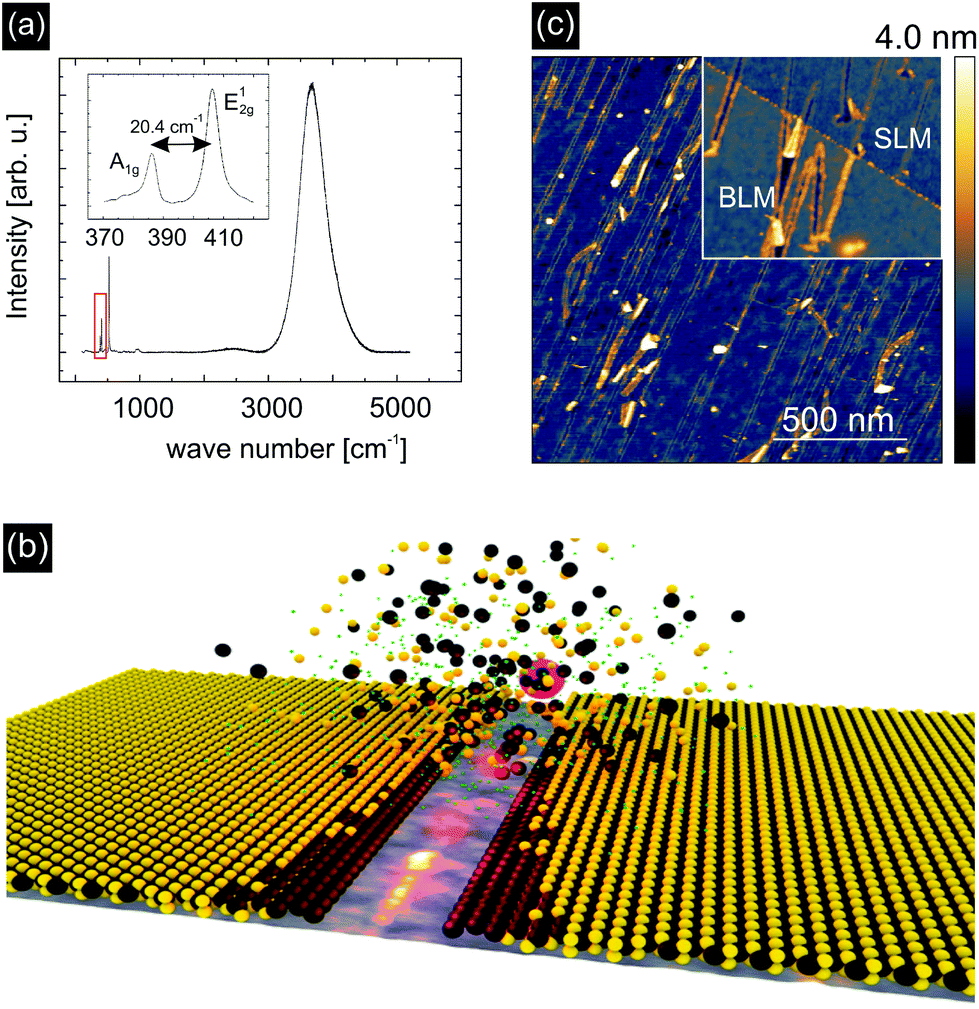 | ||
| Fig. 1 (a) Raman- and PL spectroscopy of pristine SLM. (b) Schematic illustration of rift formation with desulfurized low-coordinated Mo edges in MoS2 on SiO2 due to ion impact. (c) Atomic Force Microscopy (AFM) images after ion irradiation show the result of the ion impact under grazing incidence with respect to the MoS2 surface. Elongated rifts in the MoS2 are formed along the ion trajectory which increases the concentration of catalytically active edges. The inset presents an AFM topography image of single- and bilayer MoS2 after exposure to air for an extended period of time. | ||
Fig. 1(b) schematically illustrates the mechanism of defect formation in MoS2 by SHI irradiation. The removal of material around the ion track leaves edges behind consisting of under-coordinated Mo atoms. Furthermore, due to the thermal spike induced by the ion, also adjacent S atoms are likely to evaporate during the process. Both the low-coordinated Mo atoms at the edges of the nano-incisions and the additional S vacancies are expected to contribute to the catalytic activity. Atomic force microscopy (AFM) images of SHI irradiated MoS2 samples, acquired after exposure of the samples to air for extended periods of time, show that the edges of the incisions are heavily decorated with adsorbates, see the inset of Fig. 1(c). This is an indication of an enhanced chemical reactivity and is also found for bilayer MoS2 (BLM) samples.
To test our hypothesis and to investigate the catalytic activity of our defect-engineered samples in detail we irradiated SLM with 91 MeV Xe ions under grazing incidence at an angle of Θ = 1° with respect to the surface and with a fluence (number of ions per area) of 15 ions per μm2. The corresponding energy deposited per track length was Se = 19 keV nm−1 into MoS2, Se = 12 keV nm−1 into SiO2, and Se = 9.3 keV nm−1 into glassy carbon.40 AFM images were obtained on irradiated samples directly after irradiation, see Fig. 1(c). The AFM images reveal elongated irradiation induced incisions in the MoS2 with an average length of 400 nm ± 200 nm on SiO2 (at 1° ion incidence with respect to the surface). Assuming that the edges are completely desulfurized we would arrive at an upper limit for the efficiency of ∼4800 S atoms per incident ion, which corresponds to a sulfur vacancy density of ca. 7.2 × 104 μm−2 for these given irradiation parameters. It should be noted that the length and the density of the incisions can be easily controlled during irradiation by varying the angle with respect to the surface and choosing a higher or lower ion fluence, respectively. At too high fluences however, tracks will start to overlap so that the achievable sulfur vacancy density will saturate at some stage.
The effect of ion irradiation on the morphology of the samples is also evident in scanning electron microscopy (SEM) images. Representative examples of both irradiated and non-irradiated MoS2 surfaces on GC are shown in Fig. 2. In addition to the incisions that are formed along the direction of the ion beam, three-dimensional structures with typical sizes of a few dozens of nm are also formed due to the bombardment of the surface with SHI. The latter consist of folded material and are a result of two incisions running very close to each other.37 These “Origami-like” structures exhibit a large surface area and a large number of edge sites and are thus expected to be beneficial for the catalytic activity of the material. From a comparison of SHI induced incisions in MoS2 deposited on SiO2 (Fig. 1) and on glassy carbon, (Fig. 2), it becomes evident that both exhibit similar morphological properties. We can thus infer that the creation mechanism is the same for the two substrates. No SHI-induced three-dimensional structures were observed in areas of the glassy carbon substrate surface which were not covered by a single layer of MoS2 (Fig. S3†). Thus, these morphological features are characteristic of the MoS2 system and not of the underlying support.
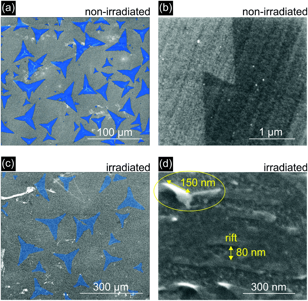 | ||
| Fig. 2 SEM images of non-irradiated (a), (b) and ion-irradiated (c), (d) MoS2 monolayers deposited on GC. The irradiated surface exhibits nanometer-scale morphological features, such as incisions (∼80 nm wide and several μm long) and three-dimensional “Origami-like” structures (see the example in the circle and ESI Fig. S2 and S3†), which are characterized by a large number of under-coordinated edge sites. The non-irradiated surfaces are flat and featureless except for the intrinsic roughness of the glassy carbon substrate. The MoS2 areas in (a) and (c) are highlighted in blue. The marked sample regions are used in the calculation of the geometric surface area. | ||
To obtain a microscopic image of the ion induced modifications, we performed molecular dynamics (MD) simulations. Irradiation was simulated with the inelastic thermal spike model41,42 on unsupported MoS2 under grazing incidence (1° with respect to the surface) for 91 MeV Xe ions. Note that the dimensions of the sheet were 200 × 40 nm2 (for details see the ESI†), considerably shorter than the length of the incisions as measured in the experiments.
The results are shown in Fig. 3. One can easily recognize the nano-incision in the MoS2 layer, which has two amorphous edges running parallel to each other, similar to the features seen in the AFM and SEM images in Fig. 1 and 2. The amorphization along the trajectory in Fig. 3(a) and (b) impedes the quantification of the relationship between the catalytic activity and the structural changes related to low-coordinated Mo atoms and sulfur vacancies. We therefore plotted the result in a different way by removing all sputtered Mo and S atoms from the simulation box, together with the amorphous chains on the edges, see Fig. 3(c) and (d). Here, the color of the Mo atoms corresponds to their coordination number (blue = coordination number of 6, green = coordination number of 5, red = coordination number of 4). The obtained MD data suggest that on each side of the incision roughly 29% of adjacent S atoms are missing and that 28% of the edge Mo atoms are under-coordinated (higher if the amorphous chains are also considered). This means we have to refine our initial estimate of the irradiation efficiency to approximately 1400 S atoms per incident ion, corresponding to a sulfur vacancy density of ca. 2.1 × 104 μm−2 at an ion fluence of 15 μm−2.
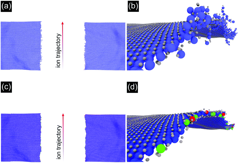 | ||
| Fig. 3 Molecular dynamics simulations of a suspended single-layer MoS2 sheet irradiated with 91 MeV Xe ions under a grazing incidence of 1° with respect to the surface. (a), (b) An incision with amorphized edges running along the ion trajectory is shown. (c), (d) For easier quantification, sputtered Mo and S atoms have been removed, together with the amorphous chains and the coordination number of the remaining Mo atoms has been color coded. Blue: Mo atoms with a coordination number of 6; green: 5, red: 4. | ||
The width of the incision in the MD simulations is smaller (∼40 nm) in comparison with the experiment (∼80 nm) probably due to neglecting the role of the substrate, which can create defects in the MoS2 in two ways. First, particles may be sputtered from the substrate resulting in further damage. This effect is assumed to be small in our case, as the cross section for nuclear stopping is negligible for SHI. However, the substrate will be heated by the thermal spike and this may also give rise to further damage. This effect cannot be neglected, in particular as the direct interaction of the beam with the 2D material is limited to a few 10 nm depending on the angle of incidence but the incisions can be much longer, i.e. a few 100 nm.
We therefore investigated the effect of the thermal spike in the substrate by applying the Two-Temperature Model (TTM).37–39 This model assumes that the energy deposited into the electronic system is transferred into the phonon system. The flow of energy from the electronic to the phonon system depends on the temperature difference between the two reservoirs and is governed by the electron–phonon-coupling constant of the material. Solving the two coupled heat diffusion equations yields spatial temperature profiles from which one can estimate whether a specific phase transition of the material occurs or not (see the ESI† for more details).
The calculated temperature profile for the SiO2 substrate irradiated with 91 MeV Xe (Se = 12.3 keV nm−1) is shown in Fig. 4. The white dotted lines depict the isotherm at 1458 K which is the decomposition temperature of MoS2.43,44 The required temperature for evaporation of S is even lower, e.g. S2 evaporates at 1140 K and in the presence of water already at 565 K by vaporizing as SO2. This indicates that indeed the substrate plays an important role for the formation of incisions. Note that we did not simulate the different substrates used for this study as we expect no significant differences in the mechanism. Quantitative differences such as deposited energy and length of incisions do exist between the different substrates. The defect creation mechanism is expected to be the same though.
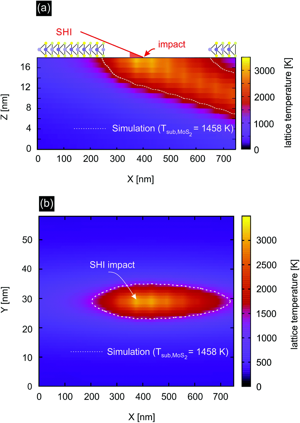 | ||
| Fig. 4 Calculated temperature profile ((a) side and (b) top view) in the SiO2 substrate after irradiation with 91 MeV Xe ions under a grazing incidence of 1° with respect to the surface. The white dotted line depicts the isotherm at the decomposition temperature of MoS2. | ||
As the simulations support our interpretation that catalytically active sites are indeed efficiently created by SHI irradiation we investigated our samples using X-ray photoelectron spectroscopy (XPS) to obtain information on the elemental composition and chemical state of the catalyst surface. The data for non-irradiated and irradiated MoS2 samples (the same irradiation conditions as before) are shown in Fig. 5. In both cases we measured a signal originating from the Mo 3d5/2 and Mo 3d3/2 peaks of MoS2 (blue) and MoO3 (green).45 In the case of non-irradiated MoS2 (Fig. 5(a)) the MoO3 contributes ∼20% to the overall Mo signal. This can be attributed to the already oxidized edges of the grown MoS2 flakes as for the XPS measurements the samples had to be exposed to ambient conditions. After irradiation, however, the MoO3 constitutes ∼49% of the overall Mo signal. We can easily explain this by assuming that the edges of the incisions created by ions in MoS2 provide additional catalytically active low-coordinated Mo atoms which are likely to oxidize when exposed to air.46
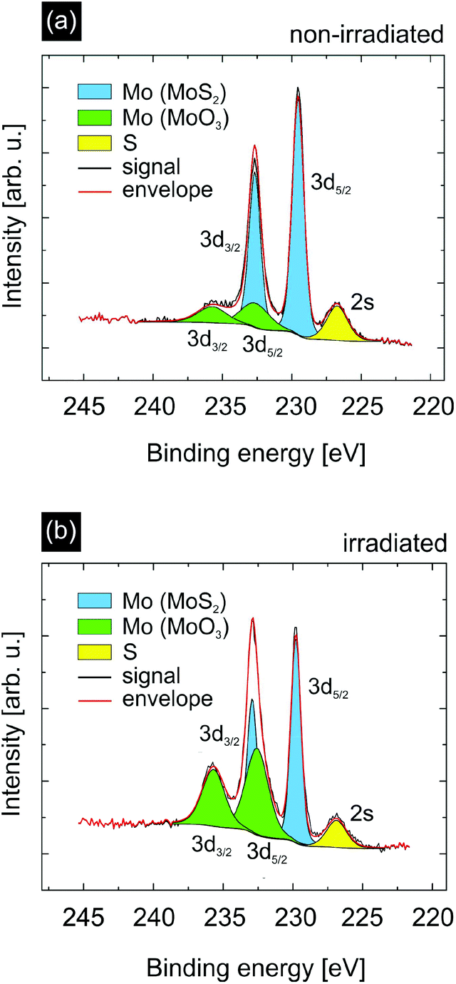 | ||
| Fig. 5 XPS spectra of non-irradiated (a) and ion-irradiated (b) single layer MoS2. The irradiation was performed with 91 MeV Xe ions under a grazing incidence of 1° with respect to the surface. One can observe a strong increase of the Mo signal originating from MoO3 for irradiated MoS2. Also, the intensity ratio of Mo/S (we refer here to the total Mo amount of both MoS2 and MoO3) strongly increases which can be explained by a lower sublimation temperature of S than Mo. | ||
Apart from these low-coordinated Mo atoms, we argue that SHI irradiation also creates S vacancies next to the incisions due to the thermal spike after ion impact because the lower sublimation temperature of S compared to Mo results in a preferential evaporation of S atoms in adjacent rows next to the ion trajectory. When analyzing the stoichiometry of Mo and S in the XPS data prior to and after irradiation using the XPS peak areas and the corresponding relative sensitivity factors (RSFs),47 we indeed see a clear increase of the total Mo![[thin space (1/6-em)]](https://www.rsc.org/images/entities/char_2009.gif) :S ratio. Whereas the Mo(MoS2):S ratio does not change upon irradiation maintaining its initial value of 0.45 (corresponding to an atomic composition of Mo0.91S2), the total Mo(MoS2 + MoO3):S ratio strongly increases from 0.56 to 0.88. In agreement with our hypothesis it is the significant increase of the MoO3 concentration which leads to the change in stoichiometry. Since SHI irradiation creates S vacancies, which are occupied by O atoms upon exposure of the sample to air, the increase of the amount of oxides in the XPS spectra after irradiation reflects the higher concentration of S vacancies (compared to the non-irradiated sample) prior to exposure to air. At least part of these O-filled vacancies becomes unoccupied again under the reducing conditions of the HER, thus contributing to the catalytic activity. Further XPS data and analysis can be found in the ESI.†
:S ratio. Whereas the Mo(MoS2):S ratio does not change upon irradiation maintaining its initial value of 0.45 (corresponding to an atomic composition of Mo0.91S2), the total Mo(MoS2 + MoO3):S ratio strongly increases from 0.56 to 0.88. In agreement with our hypothesis it is the significant increase of the MoO3 concentration which leads to the change in stoichiometry. Since SHI irradiation creates S vacancies, which are occupied by O atoms upon exposure of the sample to air, the increase of the amount of oxides in the XPS spectra after irradiation reflects the higher concentration of S vacancies (compared to the non-irradiated sample) prior to exposure to air. At least part of these O-filled vacancies becomes unoccupied again under the reducing conditions of the HER, thus contributing to the catalytic activity. Further XPS data and analysis can be found in the ESI.†
To test the extent to which the ion irradiation influences the catalytic activity of MoS2, we performed linear sweep voltammetry (LSV) measurements on non-irradiated and irradiated MoS2 in an aqueous 0.5 M H2SO4 solution (Fig. 6(a)). For these experiments glassy carbon was chosen as a substrate due to its high conductivity and inert behaviour during hydrogen evolution reaction (HER) measurements. The ion fluence for glassy carbon/MoS2 samples used for electrochemical characterization was chosen slightly higher, i.e. 40 ions per μm2, while the angle of incidence was kept at 1°. From the AFM analysis these parameters were estimated to yield a sufficiently high sulfur vacancy density without compromising sample integrity due to excessive overlapping of rifts. At a potential of −0.6 V vs. RHE, non-irradiated MoS2 (red curve) displays a current density of −13.3 mA cm−2, whereas irradiated MoS2 (blue curve) exhibits an almost three times higher current density of −35.3 mA cm−2. Large current values at low applied voltages are desirable for the HER as this qualifies the material under investigation as a suitable catalyst.
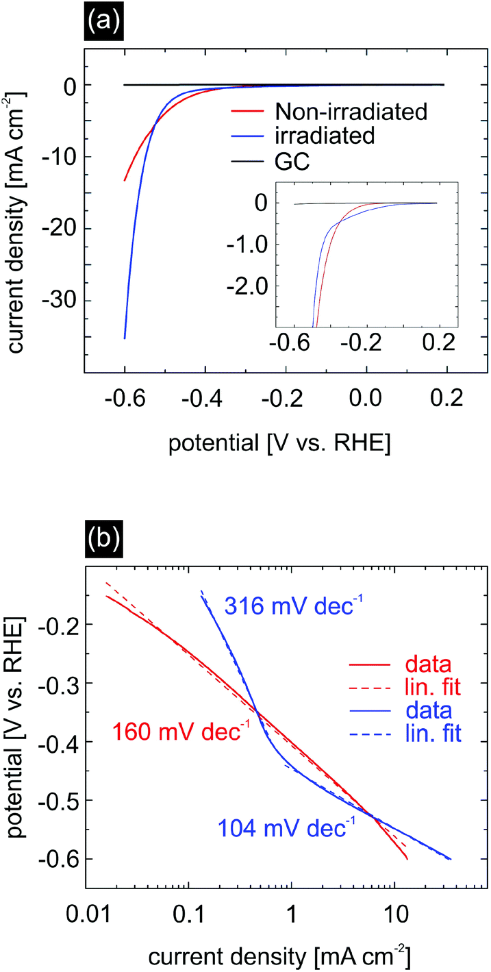 | ||
| Fig. 6 HER measurements of non-irradiated (red) and irradiated (blue) MoS2. Glassy carbon (GC) has been used as a substrate (black). Ion fluence was chosen as 40 ions per μm2. (a) Current density as a function of the potential [V vs. RHE] shows strong activity enhancement of irradiated MoS2 compared to non-irradiated MoS2. The inset of (a) shows the less negative onset potential for irradiated MoS2. (b) V–I curves with Tafel-slopes of irradiated (blue) and non-irradiated (red) MoS2. | ||
Another important characteristic of an efficient catalyst is the onset potential, which determines the necessary energy input to initiate the hydrogen evolution. It corresponds to the Gibbs free energy ΔGH of hydrogen bonding to the catalytic sites of MoS2.14,48 A large deviation from this value will lead to a too strong/too weak hydrogen adsorption which negatively affects the hydrogen desorption and electron–proton transfer, respectively, and ultimately the catalytic activity. It is therefore desirable to have materials with a ΔGH close to zero. In our experiment, we measured for pristine MoS2 an onset potential of −220 mV, which is consistent with previous studies for nanostructured MoS2.10,15,16,48,49 For ion irradiated MoS2 there is a strong indication that the onset potential decreases, e.g. in order to obtain a current density of 200 μA cm−2, the applied potential for non-irradiated MoS2 was −300 mV, whereas the potential for irradiated MoS2 was just −200 mV. This observation is in accordance with the work performed by Li et al.50 who theoretically increased the number of S vacancies, hence obtaining a minimum in ΔGH of approx. 0.02 eV at a S-vacancy density of 12.5%. In our experiment, the introduction of S vacancies and S-depleted regions is due to a thermal effect resulting from a heated substrate track along the ion trajectory as shown in TTM simulations and XPS data. Note, that determining an exact value of the onset potential for irradiated MoS2 is rather difficult due to possible non-faradaic behaviour at low currents.
We further analyzed the Tafel-slope and the exchange current density, see Fig. 6(b). The Tafel-slope can be viewed as a measure of the reaction kinetics. It is desirable that the value of the Tafel-slope is as low as possible.51,52
| ln(−j) = ln(j0) − η/b | (1) |
Here, j represents the current density, j0 is the exchange current density, b is the Tafel slope, and η is the overpotential. In the case of non-irradiated MoS2, we measured a Tafel-slope of 160 mV dec−1 which is slightly larger compared to values reported in the literature. Irradiated MoS2 however displays two independent regions with different Tafel-slopes, both differing from the slope of the non-irradiated MoS2 sample. The region with a slope of 316 mV dec−1 is likely affected by capacitance effects and shall not be considered further. For applied potentials more negative than −0.4 V vs. RHE we measured a Tafel-slope of 104 mV dec−1, which is in good agreement with the values reported in the literature for MoS2.9,10,15,16,22,24,53 The smaller Tafel slope as compared to the non-irradiated sample is also an indication of improved catalytic properties upon SHI treatment.
The exchange current density should in principle be determined by linear extrapolation of the Tafel plot in the low potential region, i.e. where the Tafel slope for the irradiated MoS2 is equal to 316 mV dec−1 (Fig. 6). However, since this region is likely affected by capacitance effects, the exchange current density determined in this way would be overestimated.
Because our catalytic material is purely two-dimensional every part of the MoS2 is in direct contact with the GC electrode which positively contributes to an efficient electron transfer (see Fig. S5 in the ESI†). Apart from the morphological changes induced by the ion irradiation, a reaction promoting effect is also expected as a result of desulfurization of the basal planes, in line with our MD and XPS data. This effect has been previously seen also for keV Ar+ beam irradiation experiments and corroborated by ab initio molecular dynamics simulations.54,55 The important role of S vacancies in the HER catalytic activity of TMDCs has also been recently demonstrated for bulk pentlandite (Fe4.5Ni4.5S8) materials.56,57 Given that the concentration of S vacancies changes during the reaction and that the interplay between desulfurization and subsequent protonation is dependent on the applied potential, a systematic study of the S vacancy effect on the catalytic activity would require operando spectroscopic studies, which are beyond the scope of this work.
Conclusion
Single layers of MoS2 have been synthesized via chemical vapor deposition and irradiated with swift heavy ions under grazing incidence. Via this defect-engineering approach, catalytically active low-coordinated Mo atoms along the incisions edges of 3D structures, as well as S depleted regions could be created. Furthermore, the density of such sites can be easily controlled by varying the irradiation parameters. We observed a strong enhancement of the catalytic activity by ∼160% as well as indications of a lowered onset potential for irradiated MoS2. Our approach constitutes an effective alternative for increasing the catalytic activity of MoS2 because it involves neither a complex synthesis procedure nor a preparation process with ligands. In contrast to other techniques, which use 3D catalysts, our 2D MoS2 catalysts promote an effective electron transfer since every part of the MoS2 is in direct contact with the GC substrate, hence minimizing charge transfer resistance. Due to the low threshold for creating incisions in MoS2 when irradiated under grazing incidence, also smaller accelerators are suitable for this defect engineering strategy. Our approach thus represents a major step towards the fundamental understanding of the role of rationally designed defects in the activity of MoS2 catalysts for HER applications.Conflicts of interest
There are no conflicts to declare.Acknowledgements
M. S. and L. M. acknowledge funding of the NU-TEGRAM project within the FLAG-ERA program by the Deutsche Forschungsgemeinschaft (DFG) (SCHL 384/16-1). B. R. C., I. Z., and Y.-W. C. acknowledge financial support from the Cluster of Excellence RESOLV at RUB (EXC 1096), funded by the DFG. S. K. acknowledges financial support from the Max Planck Research School for Interface Controlled Materials for Energy Conversion (IMPRS-SurMat). M. Q. Z., C. H. N., and A. T. C. H. acknowledge the support from the U.S. National Science Foundation (NSF) Grant EFRI 2-DARE 1542879.We thank U. Hagemann from the Interdisciplinary Center for Analytics on the Nanoscale (ICAN, core facility funded by the German Research Foundation, DFG) for support with the XPS measurements.
Notes and references
- H. B. Gray, Powering the planet with solar fuel, Nat. Chem., 2009, 1, 112 CrossRef CAS.
- A. B. Laursen, S. Kegnæs, S. Dahl and I. Chorkendorff, Molybdenum sulfides—efficient and viable materials for electro - and photoelectrocatalytic hydrogen evolution, Energy Environ. Sci., 2012, 5, 5577 RSC.
- S. Bertolazzi, J. Brivio and A. Kis, Stretching and breaking of ultrathin MoS2, ACS Nano, 2011, 5, 9703–9709 CrossRef CAS PubMed.
- G. R. Bhimanapati, Z. Lin, V. Meunier, Y. Jung, J. Cha, S. Das, Di Xiao, Y. Son, M. S. Strano, V. R. Cooper, L. Liang, S. G. Louie, E. Ringe, W. Zhou, S. S. Kim, R. R. Naik, B. G. Sumpter, H. Terrones, F. Xia, Y. Wang, J. Zhu, D. Akinwande, N. Alem, J. A. Schuller, R. E. Schaak, M. Terrones and J. A. Robinson, Recent Advances in Two-Dimensional Materials beyond Graphene, ACS Nano, 2015, 9, 11509–11539 CrossRef CAS PubMed.
- C. Lee, H. Yan, L. E. Brus, T. F. Heinz, J. Hone and S. Ryu, Anomalous lattice vibrations of single- and few-layer MoS2, ACS Nano, 2010, 4, 2695–2700 CrossRef CAS PubMed.
- A. Splendiani, L. Sun, Y. Zhang, T. Li, J. Kim, C.-Y. Chim, G. Galli and F. Wang, Emerging photoluminescence in monolayer MoS2, Nano Lett., 2010, 10, 1271–1275 CrossRef CAS PubMed.
- D. Lembke and A. Kis, Breakdown of high-performance monolayer MoS2 transistors, ACS Nano, 2012, 6, 10070–10075 CrossRef CAS PubMed.
- O. Lopez-Sanchez, D. Lembke, M. Kayci, A. Radenovic and A. Kis, Ultrasensitive photodetectors based on monolayer MoS2, Nat. Nanotechnol., 2013, 8, 497–501 CrossRef CAS PubMed.
- D. Merki and X. Hu, Recent developments of molybdenum and tungsten sulfides as hydrogen evolution catalysts, Energy Environ. Sci., 2011, 4, 3878 RSC.
- J. Kibsgaard, Z. Chen, B. N. Reinecke and T. F. Jaramillo, Engineering the surface structure of MoS2 to preferentially expose active edge sites for electrocatalysis, Nat. Mater., 2012, 11, 963–969 CrossRef CAS PubMed.
- G. Li, Du Zhang, Q. Qiao, Y. Yu, D. Peterson, A. Zafar, R. Kumar, S. Curtarolo, F. Hunte, S. Shannon, Y. Zhu, W. Yang and L. Cao, All The Catalytic Active Sites of MoS2 for Hydrogen Evolution, J. Am. Chem. Soc., 2016, 138, 16632–16638 CrossRef CAS PubMed.
- Y. Yin, J. Han, Y. Zhang, X. Zhang, P. Xu, Q. Yuan, L. Samad, X. Wang, Y. Wang, Z. Zhang, P. Zhang, X. Cao, B. Song and S. Jin, Contributions of Phase, Sulfur Vacancies, and Edges to the Hydrogen Evolution Reaction Catalytic Activity of Porous Molybdenum Disulfide Nanosheets, J. Am. Chem. Soc., 2016, 138, 7965–7972 CrossRef CAS PubMed.
- J. Xie, J. Zhang, S. Li, F. Grote, X. Zhang, H. Zhang, R. Wang, Y. Lei, B. Pan and Y. Xie, Controllable disorder engineering in oxygen-incorporated MoS2 ultrathin nanosheets for efficient hydrogen evolution, J. Am. Chem. Soc., 2013, 135, 17881–17888 CrossRef CAS PubMed.
- B. Hinnemann, P. G. Moses, J. Bonde, K. P. Jørgensen, J. H. Nielsen, S. Horch, I. Chorkendorff and J. K. Nørskov, Biomimetic hydrogen evolution, J. Am. Chem. Soc., 2005, 127, 5308–5309 CrossRef CAS PubMed.
- T. F. Jaramillo, K. P. Jørgensen, J. Bonde and J. H. Nielsen, Identification of Active Edge Sites for Electrochemical H2 Evolution from MoS2 Nanocatalysts, Science, 2007, 100–102 CrossRef CAS PubMed.
- J. Bonde, P. G. Moses, T. F. Jaramillo, J. K. Nørskov and I. Chorkendorff, Hydrogen evolution on nano-particulate transition metal sulfides, Faraday Discuss., 2008, 140, 219–231 RSC.
- W. P. Boone and J. G. Ekerdt, Hydrodesulfurization Studies with a Single-Layer Molybdenum Disulfide Catalyst, J. Catal., 2000, 193, 96–102 CrossRef CAS.
- B. Salmeron and G. A. Somorjai, The Adsorption and Binding of Thiophene, Butene and H2S on the Basal Plane of MoS2 Single Crystals, Chem. Phys. Lett., 1982, 90, 105–107 CrossRef.
- S. M. Ahmed and H. Gerischer, Influence of Crystal Surface Orientation on Redox Reactions at Semiconducting MoS2, Electrochim. Acta, 1987, 24, 705–711 CrossRef.
- X. Dai, K. Du, Z. Li, M. Liu, Y. Ma, H. Sun, X. Zhang and Y. Yang, Co-Doped MoS2 Nanosheets with the Dominant CoMoS Phase Coated on Carbon as an Excellent Electrocatalyst for Hydrogen Evolution, ACS Appl. Mater. Interfaces, 2015, 7, 27242–27253 CrossRef CAS PubMed.
- M.-R. Gao, M. K. Y. Chan and Y. Sun, Edge-terminated molybdenum disulfide with a 9.4 Å interlayer spacing for electrochemical hydrogen production, Nat. Commun., 2015, 6, 7493 CrossRef PubMed.
- D. Kong, H. Wang, J. J. Cha, M. Pasta, K. J. Koski, J. Yao and Y. Cui, Synthesis of MoS2 and MoSe2 films with vertically aligned layers, Nano Lett., 2013, 13, 1341–1347 CrossRef CAS PubMed.
- M. Ghorbani-Asl, S. Kretschmer, D. E. Spearot and A. V. Krasheninnikov, Two-dimensional MoS2 under ion irradiation, 2D Mater., 2017, 4, 25078 CrossRef.
- Y. Li, H. Wang, L. Xie, Y. Liang, G. Hong and H. Dai, MoS2 nanoparticles grown on graphene, J. Am. Chem. Soc., 2011, 133, 7296–7299 CrossRef CAS PubMed.
- S. Bertolazzi, S. Bonacchi, G. Nan, A. Pershin, D. Beljonne and P. Samorì, Engineering Chemically Active Defects in Monolayer MoS2 Transistors via Ion-Beam Irradiation and Their Healing via Vapor Deposition of Alkanethiols, Adv. Mater., 2017, 29, 1606760 CrossRef PubMed.
- R. A. Wilhelm, E. Gruber, R. Ritter, R. Heller, A. Beyer, A. Turchanin, N. Klingner, R. Hübner, M. Stöger-Pollach, H. Vieker, G. Hlawacek, A. Gölzhäuser, S. Facsko and F. Aumayr, Threshold and efficiency for perforation of 1 nm thick carbon nanomembranes with slow highly charged ions, 2D Mater., 2015, 2, 35009 CrossRef.
- R. A. Wilhelm, E. Gruber, R. Ritter, R. Heller, S. Facsko and F. Aumayr, Charge exchange and energy loss of slow highly charged ions in 1 nm thick carbon nanomembranes, Phys. Rev. Lett., 2014, 112, 153201 CrossRef PubMed.
- S. Akcöltekin, H. Bukowska, T. Peters, O. Osmani, I. Monnet, I. Alzaher, B. B. d'Etat, H. Lebius and M. Schleberger, Unzipping and folding of graphene by swift heavy ions, Appl. Phys. Lett., 2011, 98, 103103 CrossRef.
- J. Hopster, R. Kozubek, B. Ban-d'Etat, S. Guillous, H. Lebius and M. Schleberger, Damage in graphene due to electronic excitation induced by highly charged ions, 2D Mater., 2014, 1, 11011 CrossRef.
- O. Ochedowski, O. Lehtinen, U. Kaiser, A. Turchanin, B. Ban-d'Etat, H. Lebius, M. Karlušić, M. Jakšić and M. Schleberger, Nanostructuring graphene by dense electronic excitation, Nanotechnol., 2015, 26, 465302 CrossRef CAS PubMed.
- H. Vázquez, E. H. Åhlgren, O. Ochedowski, A. A. Leino, R. Mirzayev, R. Kozubek, H. Lebius, M. Karlušic, M. Jakšic, A. V. Krasheninnikov, J. Kotakoski, M. Schleberger, K. Nordlund and F. Djurabekova, Creating nanoporous graphene with swift heavy ions, Carbon, 2017, 114, 511–518 CrossRef.
- L. Madauß, J. Schumacher, M. Ghosh, O. Ochedowski, J. Meyer, H. Lebius, B. Ban-d'Etat, M. E. Toimil-Molares, C. Trautmann, R. G. H. Lammertink, M. Ulbricht and M. Schleberger, Fabrication of nanoporous graphene/polymer composite membranes, Nanoscale, 2017, 9, 10487–10493 RSC.
- W. Li, X. Wang, X. Zhang, S. Zhao, H. Duan and J. Xue, Mechanism of the defect formation in supported graphene by energetic heavy ion irradiation, Sci. Rep., 2015, 5, 9935 CrossRef CAS PubMed.
- R. Kozubek, P. Ernst, C. Herbig, T. Michely and M. Schleberger, Fabrication of Defective Single Layers of Hexagonal Boron Nitride on Various Supports for Potential Applications in Catalysis and DNA Sequencing, ACS Appl. Nano Mater., 2018, 1, 3765–3773 CrossRef CAS.
- O. Ochedowski, K. Marinov, G. Wilbs, G. Keller, N. Scheuschner, D. Severin, M. Bender, J. Maultzsch, F. J. Tegude and M. Schleberger, Radiation hardness of graphene and MoS2 field effect devices against swift heavy ion irradiation, J. Appl. Phys., 2013, 113, 214306 CrossRef.
- J. Hopster, R. Kozubek, J. Krämer, V. Sokolovsky and M. Schleberger, Ultra-thin MoS2 irradiated with highly charged ions, Nucl. Instrum. Methods Phys. Res., Sect. B, 2013, 317, 165–169 CrossRef CAS.
- L. Madauß, O. Ochedowski, H. Lebius, B. Ban-d'Etat, C. H. Naylor, A. T. C. Johnson, J. Kotakoski and M. Schleberger, Defect engineering of single- and few-layer MoS2 by swift heavy ion irradiation, 2D Mater., 2017, 4, 15034 CrossRef.
- E. Akcöltekin, T. Peters, R. Meyer, A. Duvenbeck, M. Klusmann, I. Monnet, H. Lebius and M. Schleberger, Creation of multiple nanodots by single ions, Nat. Nanotechnol., 2007, 2, 290–294 CrossRef PubMed.
- O. Ochedowski, O. Osmani, M. Schade, B. K. Bussmann, B. Ban-d'Etat, H. Lebius and M. Schleberger, Graphitic nanostripes in silicon carbide surfaces created by swift heavy ion irradiation, Nat. Commun., 2014, 5, 3913 CrossRef CAS PubMed.
- J. F. Ziegler, M. D. Ziegler and J. P. Biersack, SRIM – The stopping and range of ions in matter (2010), Nucl. Instrum. Methods Phys. Res., Sect. B, 2010, 268, 1818–1823 CrossRef CAS.
- G. Szenes, Comparison of two thermal spike models for ion–solid interaction, Nucl. Instrum. Methods Phys. Res., Sect. B, 2011, 269, 174–179 CrossRef CAS.
- C. Trautmann, S. Klaumünzer and H. Trinkaus, Effect of stress on track formation in morphous iron boron alloy Ion tracks as elastic inclusions, Phys. Rev. Lett., 2000, 85, 3648–3651 CrossRef CAS PubMed.
- R. Yang, Z. Liu, Y. Wang, G. Yang and H. Li, Synthesis and characterization of MoS2/Ti composite coatings on Ti6Al4 V prepared by laser cladding, AIP Adv., 2013, 3, 22106 CrossRef.
- J. M. Gordon, E. A. Katz, D. Feuermann, A. Albu-Yaron, M. Levy and R. Tenne, Singular MoS2, SiO2 and Si nanostructures—synthesis by solar ablation, J. Mater. Chem., 2008, 18, 458–462 RSC.
- D. Ganta, S. Sinha and R. T. Haasch, 2-D Material Molybdenum Disulfide Analyzed by XPS, Surf. Sci. Spectra, 2014, 21, 19–27 CrossRef CAS.
- H. Guo, Y. Sun, P. Zhai, H. Yao, J. Zeng, S. Zhang, J. Duan, M. Hou, M. Khan and J. Liu, Swift-heavy ion irradiation-induced latent tracks in few- and mono-layer MoS2, Appl. Phys. A, 2016, 122, 463 CrossRef.
- C. D. Wagner, Sensitivity factors for XPS analysis of surface atoms, J. Electron Spectrosc. Relat. Phenom., 1983, 32, 99–102 CrossRef CAS.
- J. Greeley, T. F. Jaramillo, J. Bonde, I. B. Chorkendorff and J. K. Nørskov, Computational high-throughput screening of electrocatalytic materials for hydrogen evolution, Nat. Mater., 2006, 5, 909–913 CrossRef CAS PubMed.
- T. F. Jaramillo, J. Bonde, J. Zhang, B.-L. Ooi, K. Andersson, J. Ulstrup and I. Chorkendorff, Hydrogen Evolution on Supported Incomplete Cubane-type [Mo3S4]4+ Electrocatalysts, J. Phys. Chem. C, 2008, 112, 17492–17498 CrossRef CAS.
- H. Li, C. Tsai, A. L. Koh, L. Cai, A. W. Contryman, A. H. Fragapane, J. Zhao, H. S. Han, H. C. Manoharan, F. Abild-Pedersen, J. K. Nørskov and X. Zheng, Activating and optimizing MoS2 basal planes for hydrogen evolution through the formation of strained sulphur vacancies, Nat. Mater., 2016, 15, 48–53 CrossRef CAS PubMed.
- L. Liao, J. Zhu, X. Bian, L. Zhu, M. D. Scanlon, H. H. Girault and B. Liu, MoS2 Formed on Mesoporous Graphene as a Highly Active Catalyst for Hydrogen Evolution, Adv. Funct. Mater., 2013, 23, 5326–5333 CrossRef CAS.
- P. Atkins and J. D. Paula, Atkin's Physical Chemistry, Oxford University Press, GB, 7th edn, 2002 Search PubMed.
- Z. Chen, D. Cummins, B. N. Reinecke, E. Clark, M. K. Sunkara and T. F. Jaramillo, Core-shell MoO3-MoS2 nanowires for hydrogen evolution, Nano Lett., 2011, 11, 4168–4175 CrossRef CAS PubMed.
- D. Le, T. B. Rawal and T. S. Rahman, Single-Layer MoS2 with Sulfur Vacancies, J. Phys. Chem. C, 2014, 118, 5346–5351 CrossRef CAS.
- Q. Ma, P. M. Odenthal, J. Mann, D. Le, C. S. Wang, Y. Zhu, T. Chen, D. Sun, K. Yamaguchi, T. Tran, M. Wurch, J. L. McKinley, J. Wyrick, K. Magnone, T. F. Heinz, T. S. Rahman, R. Kawakami and L. Bartels, Controlled argon beam-induced desulfurization of monolayer molybdenum disulfide, J. Phys.: Condens. Matter, 2013, 25, 252201 CrossRef PubMed.
- B. Konkena, K. Junge Puring, I. Sinev, S. Piontek, O. Khavryuchenko, J. P. Dürholt, R. Schmid, H. Tüysüz, M. Muhler, W. Schuhmann and U.-P. Apfel, Pentlandite rocks as sustainable and stable efficient electrocatalysts for hydrogen generation, Nat. Commun., 2016, 7, 12269 CrossRef CAS PubMed.
- I. Zegkinoglou, A. Zendegani, I. Sinev, S. Kunze, H. Mistry, H. S. Jeon, J. Zhao, M. Y. Hu, E. E. Alp, S. Piontek, M. Smialkowski, U.-P. Apfel, F. Körmann, J. Neugebauer, T. Hickel and B. Roldan Cuenya, Operando Phonon Studies of the Protonation Mechanism in Highly Active Hydrogen Evolution Reaction Pentlandite Catalysts, J. Am. Chem. Soc., 2017, 139, 14360–14363 CrossRef CAS PubMed.
Footnotes |
| † Electronic supplementary information (ESI) available. See DOI: 10.1039/c8nr04696d |
| ‡ Both authors have contributed equally. |
| This journal is © The Royal Society of Chemistry 2018 |