 Open Access Article
Creative Commons Attribution 3.0 Unported Licence
All-natural and highly flame-resistant freeze-cast foams based on phosphorylated cellulose nanofibrils†
Maryam
Ghanadpour
 *a,
Bernd
Wicklein
 b,
Federico
Carosio
 c and
Lars
Wågberg
 *ad
*ad
aDepartment of Fiber and Polymer Technology, KTH Royal Institute of Technology, SE-100 44 Stockholm, Sweden. E-mail: marygp@kth.se; wagberg@kth.se
bInstituto de Ciencia de Materiales de Madrid (ICMM-CSIC), c/Sor Juana Inés de la Cruz 3, 28049 Madrid, Spain
cDipartimento di Scienza Applicata e Tecnologia, Politecnico di Torino, Sede di Alessandria, Viale Teresa Michel 5, 15121 Alessandria, Italy
dWallenberg Wood Science Center at the Department of Fiber and Polymer Technology, KTH Royal Institute of Technology, SE-100 44 Stockholm, Sweden
First published on 6th February 2018
Abstract
Pure cellulosic foams suffer from low thermal stability and high flammability, limiting their fields of application. Here, light-weight and flame-resistant nanostructured foams are produced by combining cellulose nanofibrils prepared from phosphorylated pulp fibers (P-CNF) with microfibrous sepiolite clay using the freeze-casting technique. The resultant nanocomposite foams show excellent flame-retardant properties such as self-extinguishing behavior and extremely low heat release rates in addition to high flame penetration resistance attributed mainly to the intrinsic charring ability of the phosphorylated fibrils and the capability of sepiolite to form heat-protective intumescent-like barrier on the surface of the material. Investigation of the chemical structure of the charred residue by FTIR and solid state NMR spectroscopy reveals the extensive graphitization of the carbohydrate as a result of dephosphorylation of the modified cellulose and further dehydration due to acidic catalytic effects. Originating from the nanoscale dimensions of sepiolite particles, their high specific surface area and stiffness as well as its close interaction with the phosphorylated fibrils, the incorporation of clay nanorods also significantly improves the mechanical strength and stiffness of the nanocomposite foams. The novel foams prepared in this study are expected to have great potential for application in sustainable building construction.
1. Introduction
Due to the unique properties of light-weight foam materials, such as low density, high porosity, high thermal insulation1 and specific surface area,2 studies have recently been focused on manufacturing foams specifically from natural and renewable resources,1–4 and cellulose nanofibrils (CNF), disintegrated from the plant fiber cell wall,5 have been widely used as the main building block of foams to replace petroleum-based products.1,2,6 The nanofibrils with a square cross-section of 25–100 nm2 and a length of up to 1 μm in length7 have excellent mechanical properties, high length-to-diameter ratio and high specific surface area, and CNF is interesting for the manufacture of functional foams and aerogels.8 In most cases, CNF is combined with inorganic and organic components such as clay9,10 magnetic nanoparticles,3 starch,11 carbon nanotubes,5 or graphene oxide1 to obtain nanocomposite foams with specific functionalities such as high compressive strength,9 thermal insulation1 and magnetic and conducting5 properties achievable through synergistic effects. Another essential feature of the CNF-based foams is their flame-retardancy.1,12Freeze-casting, i.e. the unidirectional freezing of aqueous dispersions of nanoparticles has been shown to be a promising technique to obtain well-oriented and highly anisotropic porous materials.1,13 During the freezing procedure, the ice crystals grow along a temperature gradient, which leads to the creation of anisotropic ice crystals. The sublimation of the ice phase yields foams with a highly aligned, honeycomb-like porous structure.1,9,14–16 The foam morphology including pore orientation and size can be well controlled by adjusting the freezing conditions. Faster cooling rates result in smaller pores.1,17 So far, freeze-casting has been used to build porous scaffolds, nanocomposites,17–19 ceramics20 and biosensors,17 and the technique has also been applied to fabricate nanocellulose-based foams with exceptional characteristics such as super-insulation and high stiffness along the pore axis.1,9,21 One drawback with cellulose-based foams is however their poor fire-resistance due to low thermal stability and the flammability of pure cellulosic materials22 and the development of good flame-retardant properties is of great importance for these bio-based foams. Flame-retardant additives and inorganic elements, especially clay nanoparticles, are often used in combination with CNF to achieve flame-retardancy in cellulose-based foams and nanopapers.1,9,12,23–25 Clay nanoparticles act as intumescent barriers and contribute to the flame-retardant properties of the composite by reducing the rates of heat and mass transfer and catalyzing the char production of CNF due to the presence of metal ions in their structure.23,26
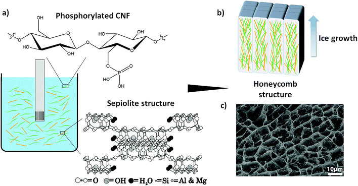
Recently, Wicklein et al. reported that the flame-retardant properties of the CNF-based freeze-cast foams are significantly improved when cellulose nanofibrils prepared from pulp fibers modified by TEMPO (2,2,6,6-tetramethylpiperidine-1-oxyl) mediated oxidation27 are used in combination with boric acid, graphene oxide and sepiolite clay (a microfibrous magnesium silicate).1,12 The enhanced flame-retardant properties are due mainly to crosslinking of nanocellulose with borate anions in the presence of clay, which shifts the char oxidation to a higher temperature and leads to less production of volatiles and combustible levoglucosan.12,28 When it comes to the industrial production of such hybrid foams, the number of incorporated components and their origin play an important role. Indeed, using as few as possible components particularly coming from abundant natural resources would effectively simplify the processing conditions and give rise to sustainable material concepts. Thus in an attempt to obtain the desired flame-retardant properties using fewer components, we have here used CNF prepared from wood fibers chemically modified by phosphorylation (P-CNF)29 combined with sepiolite clay to prepare all-natural freeze-cast foams. The P-CNF has previously shown substantial flame-retardant properties due to the presence of phosphate groups, which enhance the char-forming ability of the polysaccharide.29 The enhanced char forming ability is due to a dehydration effect of the attached phosphoryl groups, so that at high temperatures thermally stable carbonaceous char is formed, which protects the underlying polymer by limiting the heat transfer and preventing the release of combustible volatiles.30–32 The combination of P-CNF and sepiolite, both coming from natural resources, eliminates the need for any further synthetic elements, especially the potentially toxic halogenated flame-retardant additives,31,33 in order to obtain highly flame-resistant foams. Fig. 1 shows a schematic representation of the formation of P-CNF/sepiolite nanocomposite foams through freeze-casting.
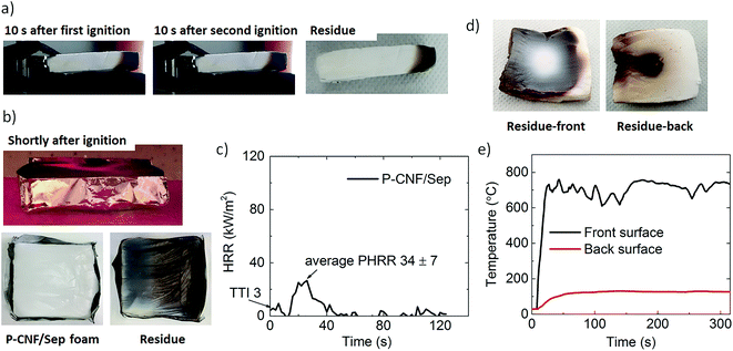
The morphology and porous structure of the foams were studied by scanning electron microscopy (SEM) and the change in their chemical structure during pyrolysis/combustion was studied using Fourier transform infrared (FTIR) and solid state nuclear magnetic resonance (NMR) spectroscopy, which showed extensive graphitization of the carbohydrate. The flame-retardancy was characterized by cone calorimetry, flammability, flame penetration, and limiting oxygen index (LOI) tests. The P-CNF/sepiolite foams displayed self-extinguishing properties in horizontal flammability, extremely low heat release rates during cone calorimetry and a LOI value of 26.5%. In addition, the foams were able to withstand the penetration of a butane flame torch (T on exposed surface ≈700 °C) for more than 5 minutes, achieving an astonishing temperature drop of 632 °C cm−1 across the foam panel. This performance is due to the intimate contact and close interaction between the phosphorylated fibrils and sepiolite combined in an organic–inorganic hybrid honeycomb-like structure, facilitated by their nanoscale dimensions. The mechanical properties were also investigated and there was a significant increase in the stiffness and strength of the composite foams when the clay was added.
2. Experimental section
2.1. Materials
The CNF used in this work was prepared from phosphorylated pulp fibers. A commercial softwood dissolving pulp (Domsjö Dissolving pulp; Domsjö Fabriker AB, Aditya Birla, Domsjö, Sweden) was used in its dried form and phosphorylation of the fibers was carried-out according to a previously described procedure.29 In brief, the fibers were first dispersed in deionized water using a laboratory reslusher. Thereafter, a 1 wt% dispersion of fibers in deionized water was prepared to which (NH4)2HPO4 and urea were added under continuous stirring, the molar ratio of anhydroglucose units of cellulose (AGU) chain to the reagents being:AGU![[thin space (1/6-em)]](https://www.rsc.org/images/entities/char_2009.gif) : :![[thin space (1/6-em)]](https://www.rsc.org/images/entities/char_2009.gif) (NH4)2HPO4 (NH4)2HPO4![[thin space (1/6-em)]](https://www.rsc.org/images/entities/char_2009.gif) : :![[thin space (1/6-em)]](https://www.rsc.org/images/entities/char_2009.gif) urea: 1 urea: 1![[thin space (1/6-em)]](https://www.rsc.org/images/entities/char_2009.gif) : :![[thin space (1/6-em)]](https://www.rsc.org/images/entities/char_2009.gif) 1.8 1.8![[thin space (1/6-em)]](https://www.rsc.org/images/entities/char_2009.gif) : :![[thin space (1/6-em)]](https://www.rsc.org/images/entities/char_2009.gif) 7.2. 7.2. |
After the impregnation, the aqueous solution was filtered to 10 wt% fiber concentration, followed by complete drying of the fibers at 50 °C and curing of the fibers at 150 °C for 10 min. The phosphorylated fibers were then washed with deionized water until the conductivity of the filtrate was less than 5 μS cm−1. The total charge of the phosphorylated fibers was determined as 1050 μeq. g−1 after the modification using conductometric titration.29 The surface degrees of substitution of phosphate (DSphosphate) and carboxylate (DScarboxylate) on the phosphorylated fibers were 0.3 and 0.4 respectively according to the XPS analysis described earlier.29 The phosphorylated (P-CNF) gel was obtained by homogenizing the 2 wt% dispersion of the modified fibers in deionized water using a high pressure homogenizer (Microfluidizer M-110EH, Microfluidics Corp.) equipped with two chambers of different sizes (200 and 100 μm). Prior to the homogenization, the pH of the dispersion was set to 9.5 using 1 M NaOH to ensure complete dissociation of carboxylate and phosphate groups. The P-CNF gel was obtained after a single pass through the large chamber (200 μm) and six passes through the small chamber (100 μm). Sepiolite clay (Sep) was supplied by Sigma Aldrich. The clay was dispersed in Milli-Q water (18 MὨ) at a concentration of 4 wt% using a high-speed disperser (Ultra-Turrax, IKA, Germany) at 12![[thin space (1/6-em)]](https://www.rsc.org/images/entities/char_2009.gif) 000 rpm for 10–15 min.
000 rpm for 10–15 min.
2.2. Methods
2.3. Characterization techniques
![[thin space (1/6-em)]](https://www.rsc.org/images/entities/char_2009.gif) 384 transients were recorded, resulting in an acquisition time of approximately 3 or 12 h, respectively. The 31P MAS NMR spectra were recorded in a Bruker Avance instrument using a MAS rate of 10 kHz and a 4 mm probe. Data were acquired using a contact time of 5 ms of a 90° pulse with a 10 s delay between repetitions. A total of 180 scans were recorded for each sample. The chemical shift values were referenced to 85% phosphoric acid (H3PO4).
384 transients were recorded, resulting in an acquisition time of approximately 3 or 12 h, respectively. The 31P MAS NMR spectra were recorded in a Bruker Avance instrument using a MAS rate of 10 kHz and a 4 mm probe. Data were acquired using a contact time of 5 ms of a 90° pulse with a 10 s delay between repetitions. A total of 180 scans were recorded for each sample. The chemical shift values were referenced to 85% phosphoric acid (H3PO4).
![[thin space (1/6-em)]](https://www.rsc.org/images/entities/char_2009.gif) :
:![[thin space (1/6-em)]](https://www.rsc.org/images/entities/char_2009.gif) 35 v/v) was applied toward the center of the samples. The distance between the torch generating the flame and the surface of the sample was set to 100 mm and the flame was applied for at least 300 s. The temperatures on the front and the back surfaces of the foams were measured using a thermocouple. The test was repeated on three independent samples.33
35 v/v) was applied toward the center of the samples. The distance between the torch generating the flame and the surface of the sample was set to 100 mm and the flame was applied for at least 300 s. The temperatures on the front and the back surfaces of the foams were measured using a thermocouple. The test was repeated on three independent samples.33
All the samples were conditioned for at least 48 h at 23 ± 1 °C and 50% RH prior to the mechanical, flammability and combustion tests.
3. Results
3.1. Sepiolite/P-CNF interactions
Fig. 2 shows the FTIR spectra of P-CNF and P-CNF/Sep foams together with the spectrum of sepiolite. As expected, the P-CNF/Sep spectrum is a combination of the signals found in the P-CNF and the sepiolite spectra. However, as shown in Fig. 2a, the P![[double bond, length as m-dash]](https://www.rsc.org/images/entities/char_e001.gif) O and P–OH bands have shifted toward lower frequency values (from 1230 to 1217 cm−1 and from 928 to 900 cm−1 respectively, shown by the blue shifts) in the P-CNF/Sep, while the P–O–C band (803 cm−1) has remained fairly unaltered compared to the signal in the spectrum of P-CNF foam.29,34,35 The Si–OH band at 3720 cm−1, present in the spectrum of sepiolite, is missing in the P-CNF/Sep spectrum due to a down-frequency shift and overlapping with the adjacent bands (Fig. 2b).12,36 These changes suggest an interaction between the phosphate groups of P-CNF and surface silanol groups of sepiolite, most probably in the form of hydrogen bonding and van der Waals interactions.10,12,36,37 The band at 1710 cm−1, which is present in the spectra of both P-CNF and P-CNF/Sep foams, can be attributed to the C
O and P–OH bands have shifted toward lower frequency values (from 1230 to 1217 cm−1 and from 928 to 900 cm−1 respectively, shown by the blue shifts) in the P-CNF/Sep, while the P–O–C band (803 cm−1) has remained fairly unaltered compared to the signal in the spectrum of P-CNF foam.29,34,35 The Si–OH band at 3720 cm−1, present in the spectrum of sepiolite, is missing in the P-CNF/Sep spectrum due to a down-frequency shift and overlapping with the adjacent bands (Fig. 2b).12,36 These changes suggest an interaction between the phosphate groups of P-CNF and surface silanol groups of sepiolite, most probably in the form of hydrogen bonding and van der Waals interactions.10,12,36,37 The band at 1710 cm−1, which is present in the spectra of both P-CNF and P-CNF/Sep foams, can be attributed to the C![[double bond, length as m-dash]](https://www.rsc.org/images/entities/char_e001.gif) O stretching mode and is probably due to oxidation which takes place during phosphorylation of the fibers.29 The band at 3688 cm−1 may refer to Mg–OH coming from sepiolite and the band centered at 3565 cm−1 in the spectra of the composite foam and sepiolite (Fig. 2b) can be due to OH stretch of coordinated water molecules that are strongly bonded to the silicate structure through Mg2+ ions (a thermal treatment above 400 °C under vacuum is required for their removal).38,39
O stretching mode and is probably due to oxidation which takes place during phosphorylation of the fibers.29 The band at 3688 cm−1 may refer to Mg–OH coming from sepiolite and the band centered at 3565 cm−1 in the spectra of the composite foam and sepiolite (Fig. 2b) can be due to OH stretch of coordinated water molecules that are strongly bonded to the silicate structure through Mg2+ ions (a thermal treatment above 400 °C under vacuum is required for their removal).38,39
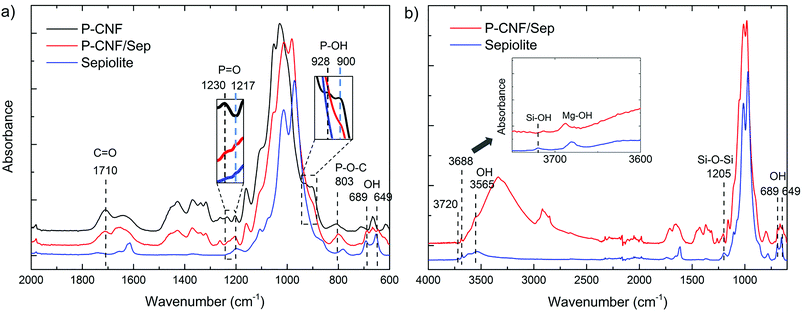 | ||
| Fig. 2 FTIR spectra of the freeze-cast foams and clay: (a) P-CNF, P-CNF/Sep foams and sepiolite and (b) P-CNF/Sep foam and sepiolite (displaying a larger region). | ||
3.2. Morphology of the foams
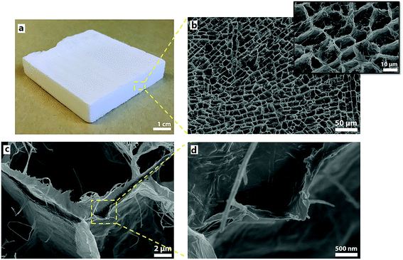
Fig. 3 shows an image of a 50 × 50 × 10 mm3 P-CNF/Sep foam panel (3a) together with SEM micrographs of the foam cross-section (3b, c and d). The well-patterned honeycomb-like cross-section of the foam shows a relatively narrow pore size distribution, which is in agreement with the previously studied freeze-cast foams.1,17 The diameter of the pores was 16.8 ± 4.6 μm (Fig. 3b). The presence of a small fraction of fibrils pointing out from the pore walls is probably due to the high cooling rate (ca. 15 K min−1) that gave insufficient time for the particles to be expelled from the ice as it was being formed.14 The tubular shape of the pores parallel to the direction of freezing is apparent in Fig. 3c, which shows the walls of a single pore. The pore cell walls are fairly smooth with a thickness estimated to be 0.5–0.7 μm. The presence of nanorods in the cell wall, which represent sepiolite particles, is further shown in the higher magnification image (Fig. 3d). As far as can be detected from the micrographs, these particles are distributed homogeneously within the P-CNF matrix.3.3. Thermal stability and flame-resistant properties
3.4. Residue analysis
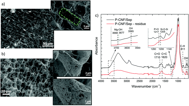
The P-CNF/Sep foam residues from the cone calorimetry and flame penetration tests were investigated by means of SEM imaging and FTIR spectroscopy (for the cone residue) to assess the changes in the morphology and porous structure and the chemical composition after burning. Fig. 5a and b show SEM micrographs of the cross-section of the samples tested by cone calorimetry and flame penetration, respectively. The initial tubular porous structure of the P-CNF/Sep foam was extensively preserved after combustion. The average pore diameter was estimated to be 14.8 ± 4.3 μm, which is very close to that of the unburned samples. The insignificant flaming during cone calorimetry can be one reason for the undamaged structure of the combusted samples. Indeed, single pores can still be distinguished even after burning the foams for more than five min (flame penetration residue). The insets in Fig. 5b show a network of sepiolite nanorods within the pore wall held together by P-CNF char. In seems that the entanglement of clay nanorods has contributed greatly to preserving the cell walls during burning.
Fig. 5c shows FTIR spectra of the unburned P-CNF/Sep foam and of the residue from the cone calorimetry. The appearance of the bands at 1620 and 811 cm−1 in the spectrum of the burned foam, which can be assigned to C![[double bond, length as m-dash]](https://www.rsc.org/images/entities/char_e001.gif) C stretching and C–H vibration respectively, indicate the formation of conjugated aromatic carbonaceous structures during combustion.44 The absence of the carbonyl C
C stretching and C–H vibration respectively, indicate the formation of conjugated aromatic carbonaceous structures during combustion.44 The absence of the carbonyl C![[double bond, length as m-dash]](https://www.rsc.org/images/entities/char_e001.gif) O band at 1710 cm−1 and of the aliphatic absorptions between 2800–3000 cm−1 in the spectrum of the burned foam, indicates the dominant presence of aromatic structures, which is in accordance with the carbonization and formation of a thermally stable char in the residue.22,44 However, the burned sample spectrum lacks the expected triplets of the charred residue in the 700–900 cm−1 region, and this suggests different degrees of substitution for the aromatic structures, which can be considered as precursors of a fully aromatic char.22,23 In addition, the P
O band at 1710 cm−1 and of the aliphatic absorptions between 2800–3000 cm−1 in the spectrum of the burned foam, indicates the dominant presence of aromatic structures, which is in accordance with the carbonization and formation of a thermally stable char in the residue.22,44 However, the burned sample spectrum lacks the expected triplets of the charred residue in the 700–900 cm−1 region, and this suggests different degrees of substitution for the aromatic structures, which can be considered as precursors of a fully aromatic char.22,23 In addition, the P![[double bond, length as m-dash]](https://www.rsc.org/images/entities/char_e001.gif) O absorption at 1217 cm−1, which is still present in the spectrum of the burned sample, indicates partial preservation of the chemical structure of phosphorylated cellulose, and this shows the extensive flame protection of the all-natural foam during combustion.32,45 The most noticeable changes in the sepiolite-related IR bands include the disappearance of the Si–O–Si signal and the band at 3565 cm−1 (assigned to coordinated water molecules) as well as the shift of the Mg–OH vibration band towards lower frequencies (3688 to 3677 cm−1). These changes may indicate the formation of monohydrated sepiolite due to dehydration of the clay at temperatures above 500 °C during combustion.46 The result is the formation of a clay-filled char, which has led to limited flaming and effective protection of the foam structure, as demonstrated by the SEM micrographs.
O absorption at 1217 cm−1, which is still present in the spectrum of the burned sample, indicates partial preservation of the chemical structure of phosphorylated cellulose, and this shows the extensive flame protection of the all-natural foam during combustion.32,45 The most noticeable changes in the sepiolite-related IR bands include the disappearance of the Si–O–Si signal and the band at 3565 cm−1 (assigned to coordinated water molecules) as well as the shift of the Mg–OH vibration band towards lower frequencies (3688 to 3677 cm−1). These changes may indicate the formation of monohydrated sepiolite due to dehydration of the clay at temperatures above 500 °C during combustion.46 The result is the formation of a clay-filled char, which has led to limited flaming and effective protection of the foam structure, as demonstrated by the SEM micrographs.
3.5. Mechanical properties
The mechanical properties of the P-CNF/Sep foams were studied by compression testing up to 90% compressive strain at 23 °C and 50% RH, and the results were compared with that of the foams prepared from pure P-CNF. Due to the anisotropic nature of freeze-cast foams, compression tests were carried out both parallel to (axial) and perpendicular to (radial) the direction of pore growth/expansion. Fig. 6 shows the typical stress–strain curves of P-CNF and P-CNF/Sep foams. Relative average values of the mechanical properties are summarized in Table 1.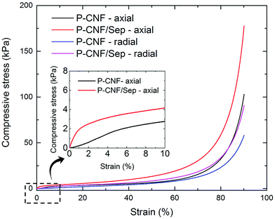 | ||
| Fig. 6 Typical stress–strain curves for the P-CNF and P-CNF/Sep foams obtained from compression in the axial and radial directions. | ||
| Sample | Density (kg m−3) | Compressive strength at 90% strain – axial (kPa) | Compressive strength at 90% strain – radial (kPa) | Young's modulus (kPa) | Specific Young's modulus (kNm kg−1) |
|---|---|---|---|---|---|
| P-CNF foam | 8.3 ± 0.2 | 100.9 ± 9.6 | 51.6 ± 10.5 | 39.0 ± 11.1 | 4.7 ± 1.3 |
| P-CNF/Sep foam | 9.2 ± 0.1 | 149.3 ± 20.8 | 87.1 ± 10.1 | 115.6 ± 17.5 | 12.6 ± 1.9 |
The stress–strain measurements show the typical deformation behavior of open-cell honeycomb-like foams, i.e. linear elasticity at low strains followed by a plateau-like region resulting from the collapse of cell walls. When the cells are completely collapsed, further strain causes a steep rise in stress since opposing cell walls are in contact and the solid material is being compressed.47 The values of compressive strength at 90% strain obtained for the P-CNF/Sep foams prepared in this work are in agreement with those of nanocellulose-based foams studied previously, but containing graphene oxide and boric acid as the cross-linking agent in addition to CNF and sepiolite.1 The compression test results presented in Table 1 further show a significant increase in compressive strength at 90% strain for the P-CNF/Sep foams compared to the P-CNF foams particularly in the axial direction. The increase in foam density upon addition of sepiolite clay is negligible. The Young's modulus was determined from the slope of the initial linear region of the stress–strain curves in the axial measurements.9 The specific Young's modulus values, normalized with respect to the material density, are 4.7 ± 1.3 and 12.6 ± 1.9 kNm kg−1 for the P-CNF and P-CNF/Sep foams respectively, which are in the same range as those previously reported for nanocellulose foams or silica aerogels (5–20 kNm kg−1).1 The specific Young's modulus of the P-CNF/Sep samples was about three times higher than that of the P-CNF foams, indicating a significant increase in stiffness due to the presence of the inorganic sepiolite.
4. Discussion
4.1. Mechanism for flame-resistant properties
The flammability, cone calorimetry and flame penetration tests clearly showed the excellent performance of the P-CNF/Sep nanocomposite foams in withstanding direct flame application or exposed to a heat flux, with a self-extinguishing behavior and the formation of coherent residues not very different from the unburned samples with regard to texture and porous structure. This can be attributed mainly to the high concentration of phosphate groups on the surfaces of the phosphorylated fibrils and fibril aggregates, which is one of the intrinsic advantages of the P-CNF.29 When the temperature is increased, cellulose undergoes pyrolysis which involves heterolytic bond scission along the molecular chain and leads to the generation of levoglucosan, a highly volatile monomer, which is the 1,6-anhydro ring formed by glucose. The instability of the C6 hydroxyl group therefore, plays a crucial role in cellulose depolymerization.28 Assuming that phosphate groups are attached mainly to the C6 hydroxyl groups,29 these sites are protected in the phosphorylated cellulose and the generation of levoglucosan during pyrolysis is inhibited and the main depolymerization mechanism of P-CNF is prevented.29 The existing phosphate groups also catalyze the dehydration of the carbohydrate at elevated temperatures, favoring the formation of thermally stable char structures despite the volatile products.29,31 In addition, as previously reported, at temperatures above 1100 °C sepiolite dehydrates to form monohydrated sepiolite and protoenstatite.39,46 In the case of P-CNF/Sep foams, the formation of monohydrated sepiolite was indicated by the difference between the IR spectrum of the residue from cone calorimetry and that of the unburned sample. The water release from clay is therefore an extra protection for the cellulose at high temperatures, assisted by the intimate contact between the phosphorylated fibrils and the sepiolite nanorods due to their high specific surface area.4,23To further obtain a better understanding of the change in chemical structure during pyrolysis, the freeze-cast foams were investigated by solid state NMR. The 31P MAS and 13C CP/MAS NMR spectra of the P-CNF foam and the P-CNF/Sep foams at room temperature (as prepared), 180 and 450 °C are shown in Fig. 7a and b, respectively. The two latter samples were thermally annealed in N2 at temperatures corresponding to before (180 °C) and after (450 °C) char formation based on the thermogravimetry data. Studying the pyrolysis in N2 is essential, as it resembles the flaming combustion which occurs in an oxygen-depleted atmosphere. The sharp signal at 0.4 ppm present in the 31P MAS spectrum of P-CNF foam can be assigned to phosphate functionalities.48 This chemical shift is typical for phosphoric mono- and diesters and is due to the presence of phosphoric esters in cellulose chain, resulting from phosphorylation.29 The broader signal centered at −10.3 ppm can be assigned to polyphosphates and this reveals the partial condensation of phosphoric esters in the structure of phosphorylated cellulose.48,49 The incremental downfield shift of the former signal (0.4 to 0.3) together with the appearance of a clear peak at −10.2 ppm in the spectrum of P-CNF/Sep foam may be related to electrostatic interactions with the clay surface. The nature of these interactions is probably hydrogen bonding between phosphate groups and surface silanol groups of sepiolite as demonstrated by the FTIR analysis.36,50 These signals are broadened and shifted when the composite foams are heated up to 180 °C, probably due to dehydration of the phosphoric esters. The phosphate ester signal decreased significantly however when the sample was heated to 450 °C, while the signal assigned to polyphosphates increased considerably. These changes may be attributed to dephosphorylation of modified cellulose during pyrolysis followed by condensation of phosphate units through water elimination to form polyphosphates. The dehydration and subsequent dephosphorylation at the C6 hydroxyl group can promote char formation as opposed to volatilization, as illustrated by the reaction routes in Fig. 7c.51,52 This is in agreement with the presence of a broad peak centered at 128 ppm in the 13C CP/MAS spectrum of the P-CNF/Sep samples treated at 450 °C, which is attributed to sp2 bonded carbons (C![[double bond, length as m-dash]](https://www.rsc.org/images/entities/char_e001.gif) C). This signal reveals extensive carbonization and conversion of the polysaccharide to aromatic graphitized structures (char) during pyrolysis.12,53 The appearance of a sharp peak at 32 ppm may be due to –CH2– carbons of aliphatic chains, which may be acting as precursors of the char and result in complete graphitization of the polysaccharide when the foams are pyrolyzed for longer times.22 The similarity of the 13C CP/MAS spectra of the P-CNF and P-CNF/Sep foams at room temperature and 180 °C can also imply that the interaction between phosphorylated fibrils and the clay nanorods is mostly in the form of hydrogen bonding in addition to the significant van der Waals interactions between the materials.
C). This signal reveals extensive carbonization and conversion of the polysaccharide to aromatic graphitized structures (char) during pyrolysis.12,53 The appearance of a sharp peak at 32 ppm may be due to –CH2– carbons of aliphatic chains, which may be acting as precursors of the char and result in complete graphitization of the polysaccharide when the foams are pyrolyzed for longer times.22 The similarity of the 13C CP/MAS spectra of the P-CNF and P-CNF/Sep foams at room temperature and 180 °C can also imply that the interaction between phosphorylated fibrils and the clay nanorods is mostly in the form of hydrogen bonding in addition to the significant van der Waals interactions between the materials.
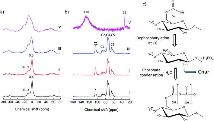 | ||
| Fig. 7 Analysis of the chemical structure of the foams during pyrolysis: (a) 31P MAS NMR spectra and (b) 13C CP/MAS NMR spectra (with assignment of different carbons of the anhydroglucose units) of P-CNF foam (I), as prepared P-CNF/Sep foam (II), P-CNF/Sep foam treated at 180 °C (III) and P-CNF/Sep foam treated at 450 °C (IV); (c) reaction routes during pyrolysis of phosphorylated cellulose.52 | ||
It has previously been shown that honeycomb-like porous structures containing sepiolite and CNF can have extremely low thermal conductivity values of 16 mW m−1 K−1.1 This can reduce the heat transfer from the surface to the bulk of the foam and thus enhance the P-CNF char-formation.23 The thermally stable aromatic char formed during combustion, as indicated by NMR analysis of pyrolyzed samples, has functioned as a thermal shield, reducing the rate of heat transfer and the release of volatiles from the sample surface, resulting in significant flame-resistance.29,31
4.2. Mechanical performance
Foamed materials must possess reasonable mechanical properties especially for the all-natural foams of the current work, which mainly aim at the construction sector. It is known that the addition of nanometer-sized elements to the cell walls of the polymeric foams may enhance the mechanical and physical properties of the resulting nanocomposite materials.11,54 The nanoscale dimension of the sepiolite particles, together with their rather high specific surface area and stiffness, makes them desirable as reinforcement elements provided that there is a significant interaction between the P-CNF and the sepiolite.4 In the case of P-CNF/Sep foams, the high (external) specific surface areas of the phosphorylated cellulose nanofibrils and the sepiolite (134 and 160 m2 g−1, respectively)4,29 promoted an interaction between the two components, so that the sepiolite nanorods were well connected with the fibrils, mainly through van der Waals interactions and surface hydrogen bonding. Such interactions lead to strong interfacial adhesion between the nanocomposite components, and this is known to be a positive factor regarding reinforcement effects.55 The increase in mechanical strength in the presence of sepiolite can also be explained by the effect of clay on the porous structure of the foam. During the freezing of P-CNF/Sep suspensions, the presence of sepiolite (as foreign particles) may facilitate ice crystal nucleation by decreasing the energy barrier to nucleation and this may lead to smaller crystal sizes and cell sizes. The smaller pores are less prone to buckle and therefore improve the mechanical properties of the foam.4,56 The comparison between the pore sizes of the P-CNF and P-CNF/Sep foams indicates a 20% decrease in the average pore diameter in the presence of clay, as shown in Fig. S4.† This has probably improved the mechanical properties of the nanocomposite foam.5. Conclusions
All-natural nanocomposite foams were made by combining phosphorylated cellulose nanofibrils with sepiolite clay using a freeze-casting approach. FTIR and solid state NMR spectroscopy revealed that the interactions between the foam components are mostly van der Waals interactions and surface hydrogen bonding. The flame-resistance of the P-CNF/Sep foams was thoroughly investigated, showing exceptional properties including self-extinguishing during flammability test and heat release rates much lower than those of commercial synthetic flame-retardant foams, as evaluated by cone calorimetry measurements. In addition, the prepared foams were able to withstand the penetration of a butane flame torch achieving an impressive temperature drop through the thickness of more than 600 °C. The char forming ability of the phosphorylated fibrils combined with the extra protection from dewatering of sepiolite and the enrichment of clay at the exposed surface of the foam, acting as a ceramic shield, led to the formation of a clay-reinforced char upon combustion, protecting the foam from the action of the flame. Investigation of the chemical structure of the pyrolyzed P-CNF/Sep samples revealed an extensive transformation of the polysaccharide to graphitized structures, due to dephosphorylation of the P-CNF during pyrolysis. The mechanical properties were also studied and compared with those of the foams from pure P-CNF. The nanocomposite foams displayed an increase in compressive strength at 90% strain of ca. 50% and an increase of ca. 170% in the specific Young's modulus. The inherent mechanical strength of sepiolite and the large interfaces between the fibrils and clay nanorods are the main factors generating the mechanical improvement. The excellent flame-resistance and the promising mechanical features of P-CNF-based nanocomposite foams together with their exceptionally light weight and renewable nature make them potentially suitable for a wide variety of applications, especially in the field of construction and insulation materials.Conflicts of interest
There are no conflicts to declare.Acknowledgements
The Swedish Foundation for Strategic Research (SSF) is gratefully acknowledged for financial support and Lars Wågberg also acknowledges the Wallenberg Wood Science Center for financial support.References
- B. Wicklein, A. Kocjan, G. Salazar-Alvarez, F. Carosio, G. Camino, M. Antonietti and L. Bergström, Nat. Nanotechnol., 2015, 10, 277–283 CrossRef CAS PubMed.
- M. Hamedi, E. Karabulut, A. Marais, A. Herland, G. Nyström and L. Wågberg, Angew. Chem., Int. Ed., 2013, 52, 12038–12042 CrossRef CAS PubMed.
- R. T. Olsson, M. A. S. Azizi Samir, G. Salazar-Alvarez, L. Belova, V. Ström, L. A. Berglund, O. Ikkala, J. Nogués and U. W. Gedde, Nat. Nanotechnol., 2010, 5, 584–584 CrossRef CAS PubMed.
- M. Frydrych, C. Wan, R. Stengler, U. O. Kelly and B. Chen, J. Mater. Chem., 2011, 21, 9103–9111 RSC.
- M. Wang, I. V. Anoshkin, A. G. Nasibulin, J. T. Korhonen, J. Seitsonen, J. Pere, E. I. Kauppinen, R. H. A. Ras and O. Ikkala, Adv. Mater., 2013, 25, 2428–2432 CrossRef CAS PubMed.
- M. Pääkkö, J. Vapaavuori, R. Silvennoinen, H. Kosonen, M. Ankerfors, T. Lindström, L. A. Berglund and O. Ikkala, Soft Matter, 2008, 4, 2492–2499 RSC.
- C. Aulin, E. Johansson, L. Wågberg and T. Lindström, Biomacromolecules, 2010, 11, 872–882 CrossRef CAS PubMed.
- E. Karabulut, T. Pettersson, M. Ankerfors and L. Wågberg, ACS Nano, 2012, 6, 4731–4739 CrossRef CAS PubMed.
- A. E. Donius, A. Liu, L. A. Berglund and U. G. K. Wegst, J. Mech. Behav. Biomed. Mater., 2014, 37, 88–99 CrossRef CAS PubMed.
- M. M. González del Campo, M. Darder, P. Aranda, M. Akkari, Y. Huttel, A. Mayoral, J. Bettini and E. Ruiz-Hitzky, Adv. Funct. Mater., 2017, 1703048 CrossRef.
- A. J. Svagan, M. A. S. Azizi Samir and L. A. Berglund, Adv. Mater., 2008, 20, 1263–1269 CrossRef CAS.
- B. Wicklein, D. Kocjan, F. Carosio, G. Camino and L. Bergström, Chem. Mater., 2016, 28, 1985–1989 CrossRef CAS.
- B. W. Riblett, N. L. Francis, M. A. Wheatley and U. G. K. Wegst, Adv. Funct. Mater., 2012, 22, 4920–4923 CrossRef CAS.
- S. Deville, E. Saiz, R. K. Nalla and A. P. Tomsia, Science, 2006, 311, 515–518 CrossRef CAS PubMed.
- A. E. Donius, R. W. Obbard, J. N. Burger, P. M. Hunger, I. Baker, R. D. Doherty and U. G. K. Wegst, Mater. Charact., 2014, 93, 184–190 CrossRef CAS.
- T. Köhnke, A. Lin, T. Elder, H. Theliander and A. J. Ragauskas, Green Chem., 2012, 14, 1864–1869 RSC.
- M. C. Gutiérrez, M. L. Ferrer and F. Del Monte, Chem. Mater., 2008, 20, 634–648 CrossRef.
- S. Deville, E. Saiz and A. P. Tomsia, Biomaterials, 2006, 27, 5480–5489 CrossRef CAS PubMed.
- S. A. Barr and E. Luijten, Acta Mater., 2010, 58, 709–715 CrossRef CAS.
- S. Deville, Adv. Eng. Mater., 2008, 10, 155–169 CrossRef CAS.
- J. Lee and Y. Deng, Soft Matter, 2011, 7, 6034–6040 RSC.
- S. Soares, G. Camino and S. Levchik, Polym. Degrad. Stab., 1995, 49, 275–283 CrossRef CAS.
- F. Carosio, J. Kochumalayil, F. Cuttica, G. Camino and L. Berglund, ACS Appl. Mater. Interfaces, 2015, 7, 5847–5856 CAS.
- A. Liu and L. A. Berglund, Carbohydr. Polym., 2012, 87, 53–60 CrossRef CAS.
- A. Liu, A. Walther, O. Ikkala, L. Belova and L. A. Berglund, Biomacromolecules, 2011, 12, 633–641 CrossRef CAS PubMed.
- S. Soares, G. Camino and S. Levchik, Polym. Degrad. Stab., 1998, 62, 25–31 CrossRef CAS.
- T. Saito, Y. Nishiyama, J. L. Putaux, M. Vignon and A. Isogai, Biomacromolecules, 2006, 7, 1687–1691 CrossRef CAS PubMed.
- E. Lecoeur, I. Vroman, S. Bourbigot, T. M. Lam and R. Delobel, Polym. Degrad. Stab., 2001, 74, 487–492 CrossRef CAS.
- M. Ghanadpour, F. Carosio, P. T. Larsson and L. Wågberg, Biomacromolecules, 2015, 16, 3399–3410 CrossRef CAS PubMed.
- F. Carosio, C. Negrell-Guirao, J. Alongi, G. David and G. Camino, Eur. Polym. J., 2015, 70, 94–103 CrossRef CAS.
- F. Carosio, G. Fontaine, J. Alongi and S. Bourbigot, ACS Appl. Mater. Interfaces, 2015, 7, 12158–12167 CAS.
- T. Zhang, H. Yan, M. Peng, L. Wang, H. Ding and Z. Fang, Nanoscale, 2013, 5, 3013–3021 RSC.
- F. Carosio, A. Di Blasio, F. Cuttica, J. Alongi and G. Malucelli, RSC Adv., 2014, 4, 16674–16680 RSC.
- R. J. Coleman, G. Lawrie, L. K. Lambert, M. Whittaker, K. S. Jack and L. Grøndahl, Biomacromolecules, 2011, 12, 889–897 CrossRef CAS PubMed.
- D. M. Suflet, G. C. Chitanu and V. I. Popa, React. Funct. Polym., 2006, 66, 1240–1249 CrossRef CAS.
- B. Wicklein, M. Darder, P. Aranda and E. Ruiz-Hitzky, Langmuir, 2010, 26, 5217–5225 CrossRef CAS PubMed.
- E. Ruiz-Hitzky, J. Mater. Chem., 2001, 11, 86–91 RSC.
- E. Ruiz-Hitzky, M. Darder, F. M. Fernandes, B. Wicklein, A. C. S. Alcântara and P. Aranda, Prog. Polym. Sci., 2013, 38, 1392–1414 CrossRef CAS.
- C. Serna, J. L. Ahlrichs and J. M. Serratosa, Clays Clay Miner., 1975, 23, 452–457 CAS.
- H. Singh and A. K. Jain, J. Appl. Polym. Sci., 2009, 111, 1115–1143 CrossRef CAS.
- P. Kiliaris and C. D. Papaspyrides, Prog. Polym. Sci., 2010, 35, 902–958 CrossRef CAS.
- X. M. Hu, Y. Y. Zhao and W. M. Cheng, Polym. Compos., 2015, 36, 1531–1540 CrossRef CAS.
- T. Guin, M. Krecker, A. Milhorn, D. A. Hagen, B. Stevens and J. C. Grunlan, Adv. Mater. Interfaces, 2015, 2, 1500214 CrossRef.
- J. Alongi, F. Carosio and G. Malucelli, Polym. Degrad. Stab., 2012, 97, 1644–1653 CrossRef CAS.
- H. Y. Ma, L. F. Tong, Z. B. Xu and Z. P. Fang, Adv. Funct. Mater., 2008, 18, 414–421 CrossRef CAS.
- F. M. Fernandes, I. Manjubala and E. Ruiz-Hitzky, Phys. Chem. Chem. Phys., 2011, 13, 4901–4910 RSC.
- L. J. Gibson and M. F. Ashby, Cellular Solids: Structure and Properties, Cambridge University Press, Cambridge, 1997 Search PubMed.
- W. D. Wanrosli, R. Rohaizu and A. Ghazali, Carbohydr. Polym., 2011, 84, 262–267 CrossRef CAS.
- B. J. Cade-Menun, Talanta, 2005, 66, 359–371 CrossRef CAS PubMed.
- Y. Chunbo, Z. Daqing, L. Aizhuo and N. Jiazuan, J. Colloid Interface Sci., 1995, 172, 536–538 CrossRef CAS.
- N. Cini and V. Ball, Adv. Colloid Interface Sci., 2014, 209, 84–97 CrossRef CAS PubMed.
- B. K. Kandola and A. R. Horrocks, Polym. Degrad. Stab., 1996, 54, 289–303 CrossRef CAS.
- W. Cai, R. D. Piner, F. J. Stadermann, S. Park, M. A. Shaibat, Y. Ishii, D. Yang, A. Velamakanni, S. J. An, M. Stoller, J. An, D. Chen and R. S. Ruoff, Science, 2008, 321, 1815–1817 CrossRef CAS PubMed.
- C. Zeng, X. Han, L. J. Lee, K. W. Koelling and D. L. Tomasko, Adv. Mater., 2003, 15, 1743–1747 CrossRef CAS.
- A. J. Svagan, M. A. S. Azizi Samir and L. A. Berglund, Biomacromolecules, 2007, 8, 2556–2563 CrossRef CAS PubMed.
- M. C. Saha, H. Mahfuz, U. K. Chakravarty, M. Uddin, M. E. Kabir and S. Jeelani, Mater. Sci. Eng., A, 2005, 406, 328–336 CrossRef.
Footnote |
| † Electronic supplementary information (ESI) available: The TG and dTG/dT curves of P-CNF/Sep foam, pure P-CNF foam and sepiolite and the thermogravimetric data in nitrogen, the behavior of pure CNF foam during cone calorimetry, photographs taken during the flame penetration test showing the front and back surfaces of the P-CNF/Sep foam and the SEM cross-sectional micrographs of the pure P-CNF and P-CNF/Sep freeze-cast foams. See DOI: 10.1039/c7nr09243a |
| This journal is © The Royal Society of Chemistry 2018 |

