
Nanostructure of the deep eutectic solvent/platinum electrode interface as a function of potential and water content†
Oliver S.
Hammond
 a,
Hua
Li
b,
Christian
Westermann
c,
Azhar Y. M.
Al-Murshedi
df,
Frank
Endres
c,
Andrew P.
Abbott
d,
Gregory G.
Warr
e,
Karen J.
Edler
a and
Rob
Atkin
*b
a,
Hua
Li
b,
Christian
Westermann
c,
Azhar Y. M.
Al-Murshedi
df,
Frank
Endres
c,
Andrew P.
Abbott
d,
Gregory G.
Warr
e,
Karen J.
Edler
a and
Rob
Atkin
*b
aCentre for Sustainable Chemical Technologies, University of Bath, Claverton Down, Bath BA2 7AY, UK
bSchool of Molecular Sciences, The University of Western Australia, 35 Stirling Highway, Perth, WA 6009, Australia. E-mail: Rob.atkin@uwa.edu.au
cInstitute of Electrochemistry, Clausthal University of Technology, Arnold-Sommerfeld-Str. 6, 38678 Clausthal-Zellerfeld, Germany
dMaterials Centre, Department of Chemistry, University of Leicester, Leicester LE1 7RH, UK
eSchool of Chemistry and University of Sydney Nano Institute, The University of Sydney, Sydney, NSW 2006, Australia
fChemistry Department, Faculty of Education for Women, University of Kufa, Al-Najaf, Iraq
First published on 11th September 2018
Abstract
The interfacial nanostructure of the three most widely-studied Deep Eutectic Solvents (DESs), choline chloride:urea (ChCl:Urea), choline chloride:ethylene glycol (ChCl:EG), and choline chloride:glycerol (ChCl:Gly) at a Pt(111) electrode has been studied as a function of applied potential and water content up to 50 wt%. Contact mode atomic force microscope (AFM) force–distance curves reveal that for all three DESs, addition of water increases the interfacial nanostructure up to ∼40 wt%, after which it decreases. This differs starkly from ionic liquids, where addition of small amounts of water rapidly decreases the interfacial nanostructure. For the pure DESs, only one interfacial layer is measured at OCP at 0.5 nm, which increases to 3 to 6 layers extending ∼5 nm from the surface at 40 or 50 wt% water. Application of a potential of ±0.25 V to the Pt electrode for the pure DESs increases the number of near surface layers to 3. However, when water is present the applied potential attenuates the steps in the force curve, which are replaced by a short-range exponential decay. This change was most pronounced for ChCl:EG with 30 wt% or 50 wt% water, so this system was probed using cyclic voltammetry, which confirms the interfacial nanostructure is akin to a salt solution.
Conceptual insightsDeep Eutectic Solvents (DESs) are attracting significant research interest as electrochemical solvents, especially for electrodeposition, as they share many of the useful properties of ionic liquids, but are typically greener and cheaper. However, the interfacial liquid (double layer) structure of DESs at metal electrodes, and the effect of added water, are until now completely unexplored. Here we probe the interfacial nanostructure of the three most widely studied DESs at a Pt electrode as a function of applied potential and water content. Remarkably, added water increases interfacial liquid layering up to 40–50 wt%, but upon application of a potential the system behaves like a salt solution. These results have important implications for the rational design of DES electrochemical systems, and for other applications incorporating a solid interface such as heterogeneous catalysis, particle stability, lubrication, etc., and means that results for ionic liquid systems cannot be assumed to hold true for DESs. |
1. Introduction
Deep Eutectic Solvents (DESs) are produced by mixing a high melting point salt with a molecular ‘hydrogen bond donor’ (HBD) at the eutectic composition, where the depression in melting point is greatest. DESs can easily be formed from a wide range of commonly available, biocompatible and/or biodegradable, inexpensive components including amides, fatty acids, glycols and sugars.1–4 The most widely studied DESs combine choline or metal chlorides with urea, ethylene glycol or glycerol. For example, mixing choline chloride (ChCl; MP = 303 °C) and urea (MP = 134 °C) in a 1![[thin space (1/6-em)]](https://www.rsc.org/images/entities/char_2009.gif) :2 molar ratio produces a room-temperature liquid. At least one of the DES ions (typically the cation) has low symmetry and the capacity to form a variety of H-bonds, as does the molecular component.5–9 High entropy derived from this range of potential interactions between liquid components yields low-melting mixtures at or near eutectic compositions.
:2 molar ratio produces a room-temperature liquid. At least one of the DES ions (typically the cation) has low symmetry and the capacity to form a variety of H-bonds, as does the molecular component.5–9 High entropy derived from this range of potential interactions between liquid components yields low-melting mixtures at or near eutectic compositions.
DESs were originally developed as greener and cheaper alternatives to the related class of ionic liquids (ILs),10 and like ILs can be tailored for specific applications.4 More recently, DESs have been designated a subset of the ‘4th generation of ionic liquids’,11 and are now used as solvents for organic synthesis,12 polymers,13 and nanomaterials14 such as metal oxides15,16 and porous carbons.17–20 Emerging DES applications include separations and extractions,21 CO2 sequestration,22 and the self-assembly of large-scale structures such as micelles,23–29 polymers,30 lipids,31 and biomolecules.32–34 However, the most important DES research area is electrochemistry, especially metal electrodeposition.35 DES can be designed to have good solubility for metal ions36 and optimal electrochemical windows37 while having minimal environmental impact.38 This, along with strong industrial demand for high-quality metal coatings and films,39 means that DES are poised to become next-generation electrochemical solvents.40 However, as with ILs, the structure of DES components at an electrode interface must be known to rationally optimise electrochemical processes;41–43 in the absence of fundamental understanding of the structure of the DES electrical double layer, this goal cannot be achieved.
To date few fundamental studies of the DES double layer structure have appeared. Chen et al. examined a series of DES at HOPG electrode interfaces as a function of potential, using AFM and DFT.44 Multilayer nanostructures were found, but they were weaker (fewer layers and lower push-through forces) than for typical ILs.45 Atilhan et al. performed MD simulations for a ChCl:levulinic acid DES on the (100) surface of Ag, Al, and Pt,46 and subsequently performed DFT calculations for a series of DES on graphene.47 The structures reported for graphene were consistent with AFM measurements on HOPG,44 as well as subsequent MD simulations by Kaur et al.,48 who reported an 0.5 nm thick layer in contact with the surface, but minimal surface-induced structure beyond 1 nm. DES–metal interactions obeyed the ordering strength Pt > Al > Ag, with well-defined layers seen up to 1 nm, and weak perturbation up to 3 nm from the interface.46 Chen et al. have also studied the effect of aliphatic chain length in alkylammonium bromide DES on the interfacial structure,49 and observed that layer thickness grew proportionately with the alkyl moiety. Vieira et al. measured ChCl:ethylene glycol (EG) on a glassy carbon electrode with infrared reflection-absorption spectroscopy (IRRAS), which reveals strong surface adsorption of the EG with competition from cholinium ions.50 Other electrochemical studies assume the interfacial structure,35 or infer the structure indirectly.51,52
DESs are typically highly hygroscopic and very difficult to dry completely,53 so understanding the effect of water on the DES electrical double layer is critical for optimising electrodeposition conditions. It has recently been reported that the liquid structure of DES is largely retained in the presence of water up to 50 vol%,9 while transport properties are improved due to reduced viscosity, meaning there may be significant advantages for using wet DESs in electrochemistry. At solid–IL interfaces, nanostructure decreases with increasing water content, and above ∼50 vol% water, the IL–water mixture behaves like an aqueous electrolyte solution and interfacial nanostructure is absent.54–56 In this communication, we present results from the first study of DES nanostructure at a metal (Pt) electrode. Choline chloride:urea (ChCl:Urea), choline chloride:ethylene glycol (ChCl:EG), and choline chloride:glycerol (ChCl:Gly) are investigated as a function of water content and applied potential. Remarkably, and in stark contrast to ILs, the DES interfacial nanostructure increases with water content up to 40 vol%, which has important consequences for electrochemical behaviour.
2. Experimental
Pure DES were prepared by the common route of mixing as-received choline chloride (Sigma-Aldrich, ≥98%) in a 1:2 ratio with either ethylene glycol (Sigma-Aldrich, ≥99.8%), glycerol (Sigma-Aldrich, ≥99%), or urea (Sigma-Aldrich, ≥99.5%), with vigorous mixing and heating at 60 °C in an oil bath until the earliest point at which a homogeneous liquid formed. DES–water mixtures were subsequently prepared from these stock solutions by adding deionised H2O (Elga, 18.2 MΩ) with stirring or shaking until a homogeneous solution was formed, with complete mixing of the two mutually compatible liquids of different refractive index and density57 signalled by the disappearance of schlieren textures. As expected, low-level water was present in all the pure DES (≤0.34%) as measured by KF titration.
AFM measurements were performed using a Bruker Nanoscope IV multimode instrument operating in contact mode. For all measurements, the chosen mixture was syringed into a AFM liquid cell, where the DES was isolated from the atmosphere and held by a PTFE O-ring next to a polycrystalline platinum surface (a 60 nm layer, nominally of Pt(111), deposited onto a silicon wafer), with measured RMS roughness of 0.6 nm over a 500 nm × 500 nm area. Standard Si AFM cantilevers (model NSC36, MikroMasch, Sofia, Bulgaria) were used throughout, and the composition of the tip reflective coating was not observed to have an effect (Au or Al). Both surface and cantilever were cleaned of organics by washing thoroughly with deionised water and absolute ethanol, before drying and irradiating using a UV-Ozone cleaner for 20 minutes prior to use. The measured steps were reproducible regardless of the ramp rate or size; the higher resolution of a smaller, slower approach or retraction is offset by proportionally higher experimental noise.
Electrochemical measurements were performed using cyclic voltammetry with an Autolab PGSTAT20 software-controlled potentiostat using three electrodes; a 0.5 mm platinum wire as the working electrode, a silver wire as the reference electrode and a platinum sheet as the counter electrode. Cyclic voltammetry was performed for sodium iodide dissolved in pure ChCl:EG and repeated for each with different water contents.
3. Results and discussion
Fig. 1 presents AFM curves for pure ChCl:Urea at a Pt electrode at OCP, and OCP ±0.25 V. This potential window was examined to avoid electrochemical processes associated with water in later experiments. For all systems and potentials, the force curves presented were selected by determining the mean number of steps and push-through force for more than 100 force curves acquired over several days, which allows selection of a typical force curve which closely matches the average values. This approach is favoured over an “average” force curve, as averaging hides features that, although consistent, occur at small normal forces or slightly different separations.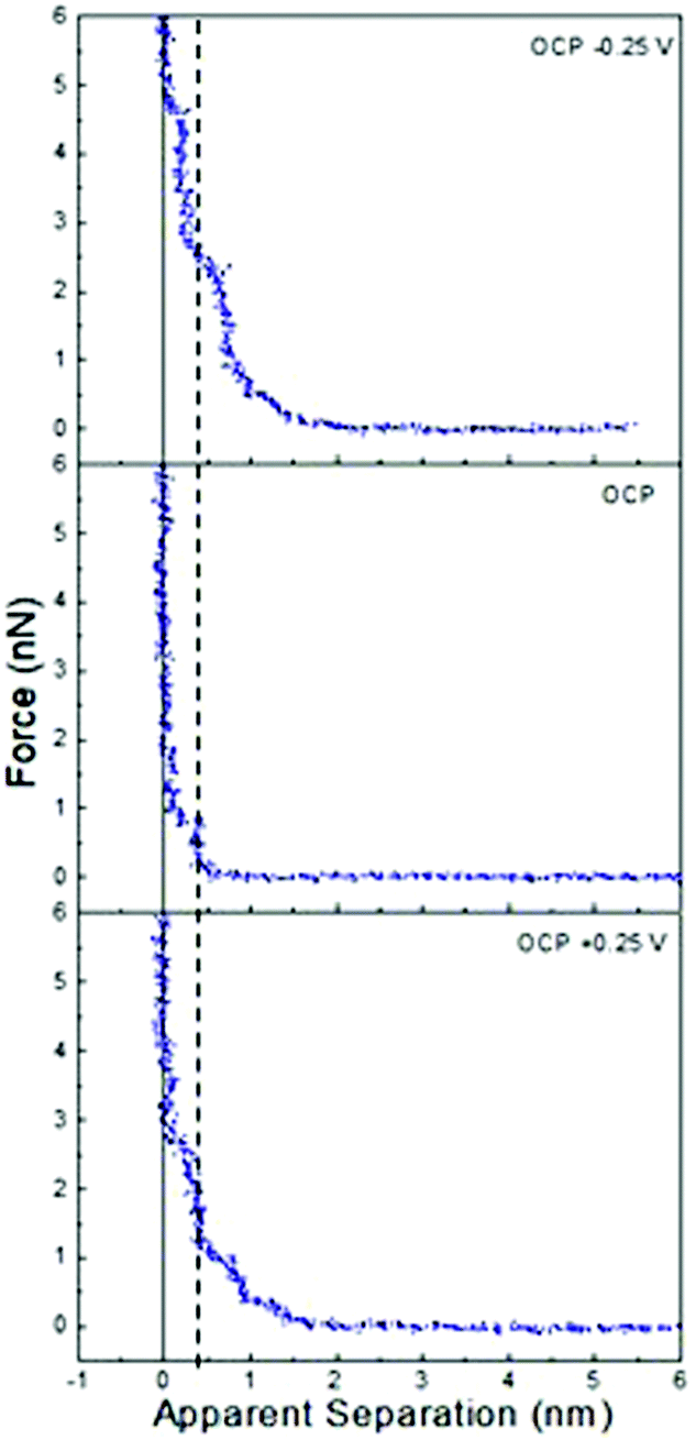 | ||
| Fig. 1 AFM force–distance profiles for pure ChCl:Urea at OCP, and OCP ±0.25 V. The dashed vertical line is at 0.45 nm. | ||
In Fig. 1, all force curves exhibit short-range repulsions that resolve into discrete steps between near-vertical force walls at small separations. The sub-nm widths of these steps are consistent with near surface liquid layers of ionic or molecular components of the DES, and show negligible underlying van der Waals attractions.
In ChCl:Urea (Fig. 1), only one step is present at OCP, but at 0.25 V and −0.25 V, the step number is increased to 3, and the ‘push-through’ force required to displace the final layer increases from 1 nN to at least 2.5 nN. While the last measured steps are almost vertical (i.e. incompressible), those further from the surface are compressible. More steps and higher push-through forces with an applied potential have been observed previously for ionic liquids on metal electrodes.41 Both here and in prior work, this has been attributed to counterion enrichment in the Stern layer, which templates better defined structure in near surface layers and through this, stronger cohesive interactions.
At positive potentials, the counterion (Stern) layer in contact with the electrode surface must be enriched in Cl−. However, the 0.45 nm final “push-through” layer, is too large to be Cl− (0.35 nm). This means, as we have found previously for ChCl:Urea on graphite,44 and many ionic liquid systems,58 at zero apparent separation the AFM tip is pushing against a counterion layer that it cannot displace. The question, then, is whether the layer in contact with the chloride-rich Stern layer is enriched in choline or urea. Previous AFM studies have shown that the liquid layers of pure glycerol and ethylene glycol in contact with a graphite surface are 0.33 nm and 0.23 nm thick, respectively. HBD-rich layers in ChCl:EG, ChCl:Gly, and ChCl:Urea DESs were also only ∼0.3 nm thick.44 The thickness of the innermost measured layer on Pt at positive potentials is, however, consistent with the diameter of Ch+ (0.43 nm).44 Therefore, at positive potentials the chloride-rich Stern layer in contact with the Pt surface which the AFM tip cannot displace is followed by a choline-rich near-surface layer. Electrostatic considerations mean the choline charge group is preferentially orientated toward the chloride and alcohol groups towards the bulk. Subsequent steps are too weak and compressible to permit an unambiguous interpretation of their composition.
At negative potentials, the Stern layer must similarly be enriched in choline, with charged groups preferentially orientated towards the surface and hydroxyl groups facing the bulk liquid. The thickness of the final measured layer is 0.3 nm, which is too thin to be either choline (0.43 nm) or chloride (0.35 nm), but is consistent with the urea-rich layers seen on graphite.44 Thus, the final measured step at positive potentials is due to a urea-rich layer, which is in contact with a choline-rich Stern layer the tip cannot displace. As with negative potentials, subsequent steps are weak.
At OCP (no applied potential) the 0.45 nm thickness of the final push-through distance is too large to indicate enrichment in chloride or urea. Therefore, we conclude the final measured layer is choline rich, as seen at positive applied potentials. Here, however, it is unclear whether this final measured layer is the Stern layer or first near surface layer. The single step seen in ChCl:Urea is much fewer than the 4 or 5 steps routinely observed in ionic liquids with similarly sized and structured ions (e.g. ethylammonium nitrate (EAN)) at surfaces with roughness similar to the Pt electrode.59,60 This is because in ChCl:Urea the ions are diluted by 2 urea molecules, whereas EAN is a pure salt. Liquid cohesion within layers is therefore reduced in the DES due to reduced electrostatics, and packing considerations.
The interfacial structure of ChCl:Urea at a Pt electrode differs markedly from that at a graphite electrode. There the thickness of the final displaceable layer was found constant between +1 V and −0.5, and attributed to displacement of a HBD rich layer in contact with an underlying impenetrable Stern layer.44 This difference is attributed to the atomically smooth graphite surface strongly aligning counterions.
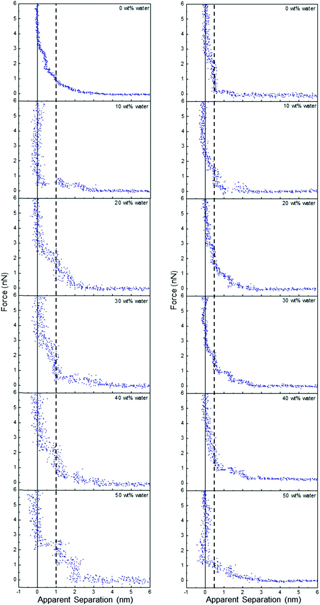
Fig. 2 presents force data for ChCl:Urea at a Pt electrode at OCP as a function of water content up to 50 wt%. To our knowledge, the effect of water on DES interfacial structure has not previously been reported using AFM force curves or any other technique. Addition of 10 wt% water changes the range and form of the force markedly, adding compressible steps with push-through jumps at 1.4 nm and 2 nm. At 20 wt% water, the number and position of the steps is the same, but they are more pronounced, and at 30 wt% water, a fourth weak step appears at ∼2.7 nm. When the water content is further increased to 40 wt% there are at least 6 steps in the force curve extending 5.5 nm into solution, and the force required to rupture the final layer increases from 2 nN to 5 nN. At 50 wt% water, the push through force is again reduced to 2 nN, but at least 5 interfacial layers remain visible, extending further into the liquid than at water contents of 30 wt% and lower. The thickness of the final penetrable layer increases with water content from 0.45 nm at in pure ChCl:Urea to ∼0.55 nm for 40 and 50 wt% water.
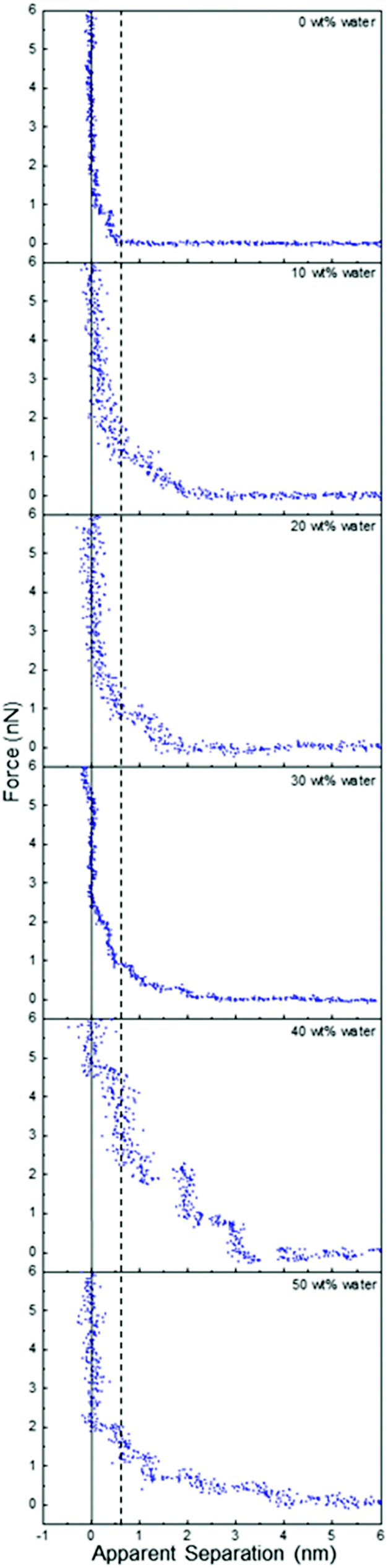 | ||
| Fig. 2 AFM force–distance profiles for ChCl:Urea with different water contents at OCP. The dashed vertical line is at 0.55 nm (see text). | ||
This trend of water increasing DES interfacial nanostructure up to 40 wt%, followed by a slight weakening at 50 wt%, stands in stark contrast to ionic liquid systems, where added water only weakens interfacial nanostructure. For example, for a silica substrate (which has roughness comparable to the Pt electrode) in contact with EAN, the interfacial nanostructure associated with the pure liquid is almost completely eliminated by addition of 10 wt% water, and by 25 wt% water the force curves are consistent with a salt solution.54
To understand the trends in ChCl:Urea interfacial nanostructure, the force data must be considered in conjunction with the bulk liquid structure of ChCl:Urea5 and its mixtures with water.61 Neutron diffraction and fitting reveals that in bulk ChCl:Urea, the choline and urea preferentially bind to chloride atoms while maximising weaker interactions with each other.5 Water added to ChCl:Urea up to 40 wt% preferentially associates with the cholinium ion, with corresponding weakening of interactions between the DES components (cholinium, chloride and urea). Water hydrates the pure DES by sequestration around the cholinium cation, but the liquid structure is otherwise little changed.18,61,62 Beyond 40 wt% water the mixture is much less structured, and is better described as a solution of DES components in water.
In the context of these bulk trends, the changes in ChCl:Urea interfacial nanostructure as a function of water content can be understood. Up to 30 wt%, added water associates with the cholinium ions (probably via the outward-facing hydroxyls) in the last penetrable layer such that its thickness remains approximately constant at 0.45 nm. Its participation in the hydrogen bond network of the mixture strengthens cohesive interactions laterally in this layer, which increases the push-through force and templates stronger structure in near-surface molecules and ions, leading to the detection of additional layers. These layers also contain water, as neutron diffraction shows significant chloride–water and urea–water interactions (but weaker than for cholinium water). The number and strength of layers increases with water content up to at least 30 wt% as the choline–water coordination number grows.
The most highly-structured interface (highest push through forces and greatest number of layers) occurs at 40 wt% water. Here the cholinium ion coordination by water is at a maximum, but has not yet transitioned to a DES-in-water solution. The hydrogen bond network of water and the DES components leads to an increase in the thickness of the final layer, and the sharply increased number of layers results from the combined effects of the smooth, solid surface, and the cohesive forces that drive the underlying liquid structure; a well-formed first layer templates structure in the second layer, and so on, with order gradually decaying into the bulk. These swollen DES structures are less deformable under the pressure of the AFM, which leads to more vertical steps and higher push through forces.
At 50 wt% water in ChCl:Urea, the bulk data reveals a DES-in-water mixture. However, accumulation of ions at the Pt surface will lead to a higher interfacial ion concentration than in the bulk, especially when confined by the AFM tip, the surface of which has its own, less well defined,63–65 interfacial nanostructure. Consequentially, the elevated interfacial ion concentration causes much of the strong interfacial nanostructure observed at 40 wt% water to be retained at 50 wt% water. The decrease in push through forces and number of layers, the compressibility of near surface layers, and decreased width of the final step in the force data at 50 wt% water is consistent with the system tending towards a DES-in-water solution.
Fig. 3 presents AFM force data for ChCl:Urea with 30 and 50 wt% water at OCP, and ±0.25 V; the OCP data is reproduced from Fig. 2 to enable direct comparison. The steps in the force data at OCP are significantly altered when a potential is applied, such that a short-range exponential decay becomes the dominant feature, superimposed with weak steps. At negative potentials, a weak attraction is observed between 3 nm and 5.5 nm for both 30 and 50 wt% water.
 | ||
| Fig. 3 AFM force–distance profiles for ChCl:Urea with 30 wt% water (left) and 50 wt% water (right) at OCP, and OCP ±0.25 V. | ||
When a potential is applied to the Pt electrode, counterions are attracted to the interfacial regions, and co-ions repelled.66 This means that when a positive or negative potential is applied, the counterion to co-ion ratio in the liquid ratio adjacent to the adsorbed layer is unbalanced, which hinders ion packing into layers, and the AFM tip measures an exponential decay consistent with this. Any weak steps in the force curves are due to the weakly structured counterion layers.
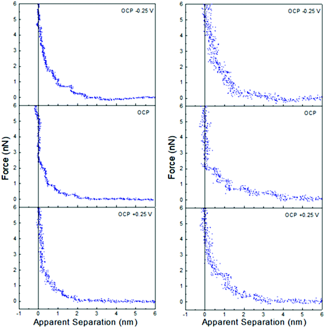
AFM force curve data as a function of potential and water content for the two most studied polyol-based DESs, ChCl:EG, and ChCl:Gly parallel many of the results found in ChCl:Urea. Much less is known about the bulk liquid structures of pure ChCl:EG, and ChCl:Gly than ChCl:Urea at the molecular level, and almost nothing about their the effect of added water; neutron spin-echo measurements suggest that the ChCl:Gly structure is reminiscent of glycerol, with the ions occupying interstitial voids.67
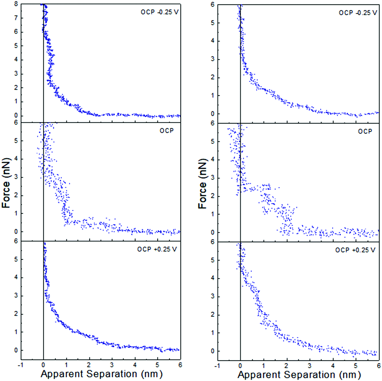
Fig. 4 shows that the interfacial nanostructure of pure ChCl:EG and ChCl:Gly at a Pt electrode is strongly affected by application of potential. At positive potentials, when an impenetrable, chloride-rich Stern layer in contact with the surfaces defines zero apparent separation, the layer nearest the surface of both DESs is 0.45 nm thick. This layer must be enriched in choline in both ChCl:EG, and ChCl:Gly, just as it is in ChCl:Urea, as it is too thick to be due to either chloride or the HBD. At negative potentials, the Stern layer is enriched in choline with charged groups facing the electrode and alcohol groups facing the bulk liquid. The thicknesses of the final displaceable layers of ChCl:EG, and ChCl:Gly are 0.25 nm and 0.30 nm, respectively, which are close to the corresponding layer thicknesses of pure ethylene glycol (0.23 nm) and glycerol (0.33 nm). In both ChCl:EG and ChCl:Gly the final measured layer at negative potentials is HBD-rich, sitting atop a choline-rich impenetrable Stern layer. At OCP, the thicknesses of the final measured layers are 0.45 nm and 0.50 nm for ChCl:EG, and ChCl:Gly, respectively. This thickness is again consistent with a choline enriched layer but, as with ChCl:Urea, it is unclear whether this corresponds to the Stern layer, or the first near surface layer.
 | ||
| Fig. 4 AFM force–distance profiles for pure ChCl:EG (left) and ChCl:Gly (right) at OCP, and OCP ±0.25 V. The dashed vertical lines are at 0.45 nm. | ||
At larger separation there is evidence for liquid nanostructure extending into solution. At OCP in ChCl:Gly a weak second layer is detected, and in ChCl:EG, additional steps are superimposed on a weak exponential decay consistent with a salt solution.
Application of ±0.25 V to the Pt electrode surface increases the force required to rupture the final layer of both ChCl:EG and ChCl:Gly. As with ChCl:Urea, this is attributed to counterion-enriched, well ordered, Stern layers enhancing structure, templating subsequent near surface layers. This is seen in an increase in the number of steps in the force curve of ChCl:Gly, just as in ChCl:Urea, but not for ChCl:EG. This suggests differences between the H-bond networks supported by the three HBDs analogous to the effects of molecular flexibility disrupting interfacial layering in ionic liquids59 and pure molecular liquids.68 This would be consistent with bulk liquid structures that became more like electrolyte solutions as one progresses from urea to glycerol to ethylene glycol.
Fig. 5 shows that water addition to ChCl:Gly at OCP also parallels the behaviour of ChCl:Urea, but ChCl:EG is again qualitatively different. Water addition to ChCl:Gly increases the number of discrete steps from two to 4 at 30 wt% water, and then decreases as the layering becomes less pronounced. This shows that, like ChCl:Urea, interfacial structure is strongest for ChCl:Gly in the range 30–40 wt%. As water content is increased, the thickness of the step nearest the surface remains approximately constant at 0.5 nm, but the width of subsequent steps is much greater, at ∼0.9 nm. This is too large to be due to any individual or hydrated DES component. This reveals water molecules drive stronger associations between DES components, which are displaced from the space between the AFM tip and the Pt electrode as aggregates.
 | ||
| Fig. 5 AFM force–distance profiles for ChCl:EG (left) and ChCl:Gly (right) with different water contents as indicated. The vertical line is at 1 nm for ChCl:EG and 0.5 nm for ChCl:Gly. | ||
The effect of added water on ChCl:EG is dramatic, cf.Fig. 5. The 0.5 nm step nearest the surface and subsequent weak exponential decay measured in the pure DES are replaced by two (or more) layers each 1 nm thick. The interfacial structure as measured by the number and definition of layers clearly increases with water addition up to 50 wt%. Further increasing water content up to 90 wt% water diminishes the observed structure (see Fig. E1 of the ESI†). Notably, in Fig. E1 (ESI†), a clear step in the force curve is observed even for 80 wt% water, and attractive interactions consistent with a high salt concentration aqueous solution only emerge between 80 wt% and 90 wt% water. This is dramatically different from EAN, where attractive forces are detected above 75 wt% water due to van der Waals forces dominating the overall interaction.
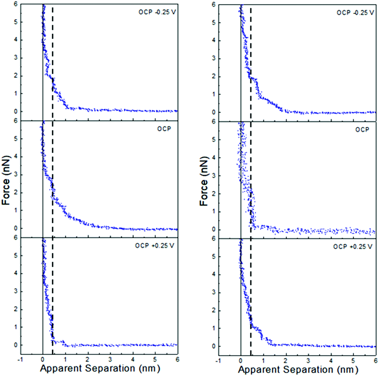
Force data at OCP, and OCP ±0.25 V, for ChCl:EG with 30 wt% water and 50 wt% water is presented in Fig. 6, and ChCl:Gly with 30 wt% water and 50 wt% water in Fig. 7. For ChCl:EG the pronounced steps at OCP, indicating strong interfacial structure, almost disappear when a potential is applied and are replaced with a short-range exponential decay. A similar effect is noted for ChCl:Gly, but some weak steps can be discerned superimposed on the exponential decay. This is surprising, given that the steps in the force curve at OCP are significantly wider and have higher push through forces for ChCl:EG than ChCl:Gly. This shows the DES nanostructure at OCP is not strongly related to the structure when a potential is applied. On the evidence available it is concluded that the exponential decay is a consequence of counterions being attracted into, and co-ions repelled from the Stern and near surface liquid layers when a potential is applied, as per the ChCl:Urea data presented in Fig. 3, and the environment experienced by the tip is more like a salt solution.
 | ||
| Fig. 6 AFM force–distance profiles for ChCl:EG with 30 wt% water (left) and 50 wt% water (right) at OCP, and OCP ±0.25 V. | ||
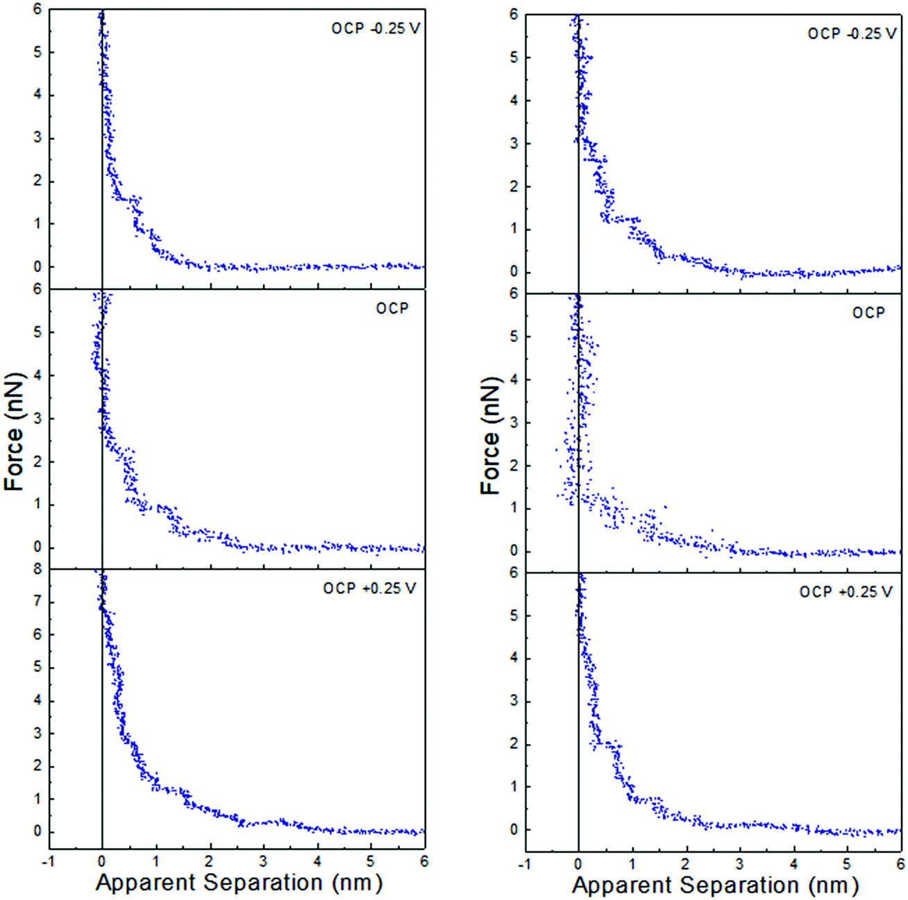 | ||
| Fig. 7 AFM force–distance profiles for ChCl:Gly with 30 wt% water (left) and 50 wt% water (right) at OCP, and OCP ±0.25 V. | ||
Of the three DESs investigated in this work, the effect of applying a potential to the Pt electrode when water is present (at either 30 wt% or 50 wt%) is greatest for ChCl:EG: this system has the largest steps at OCP with added water, and these steps almost completely disappear when a potential is applied. OCP interfacial structure is weaker for ChCl:Urea than ChCl:Gly at 30 wt% water, and especially 50 wt% water, and when a potential is applied weak steps overlay the exponential decay. Therefore, as the effect of potential with added water was greatest for ChCl:EG, this system was studied more closely using cyclic voltammetry.
Fig. 8 (left) shows cyclic voltammograms obtained in ChCl:EG containing 0.1 mol dm−3 sodium iodide at a scan rate of 10 mV s−1. In pure ChCl:EG two well-defined electrochemically reversible redox peaks can be observed for NaI with formal potentials of 0.73 V and 0.92 V. The first peak is related to the electrochemical oxidation of iodide to form triiodide. The peak occurring at more positive potentials is related to the oxidation of triiodide to iodine as per eqn (1) and (2).69,70
| 3I− − 2e− ↔ I3− | (1) |
| I3− − e− ↔ 3/2I2 | (2) |
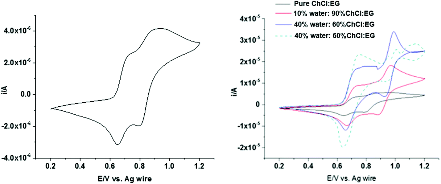 | ||
| Fig. 8 Cyclic voltammograms of 0.1 mol dm−3 NaI in (left) ChCl:EG and (right) ChCl:EG with different amounts of water measured at a scan rate of 4 mV s−1. | ||
Iodine is relatively hydrophobic and is relatively insoluble in aqueous solutions, so it tends to precipitate on the electrode surface. However, we have recently shown that iodine is very soluble in DESs due to the formation of I2Cl−, but as the water content increases the solubility of iodine decreases significantly.71,72 Therefore, changing double layer from ion dominated to water dominated should be evident in the shape of the voltammogram. Fig. 8 (right) shows the cyclic voltammograms for 0.1 mol dm−3 sodium iodide with water contents from 0 to 50 wt% at a scan rate of 4 mV s−1. The electrochemical response changes as water is added, with the second peak becoming much sharper with an increased amount of water in the mixture. The nanoscale heterogeneity of DES–water mixtures has been demonstrated using Brillouin spectroscopy,62 neutron diffraction,9,61 and PFG-NMR,73 the latter of which highlighted variability between the diffusion coefficients of water and DES components. Considering this alongside the known strong interaction between water and halide anions, it is proposed that I− will preferentially transport through water-rich regions.73 At 50 wt% water, the voltammogram is characteristic of the response obtained in an aqueous solution of iodide, confirming the presence of water in the double layer.
4. Conclusions
AFM force curves have been used to probe the liquid interfacial (double layer) structure of the three most widely used DESs (ChCl:Urea, ChCl:EG and ChCl:Gly) at a Pt electrode as a function of applied potential and water contents. Analysis of the data reveals the interfacial arrangements of liquid components depends strongly upon water content and applied potential, Differences between DES with different HBD type are less pronounced.For the pure DESs, 1 or 2 steps are measured at OCP, which increases to 2 or 3 steps upon application of a ±0.25 V potential. This is attributed to increased ordering of Stern layer ions templating structure in subsequent layers.
When water is added to the DESs, interfacial nanostructure increases up to 40 wt% for ChCl:Urea, 30% for ChCl:Gly, and 50 wt% for ChCl:EG. This is a startling result, as added water dilutes the ions, which was expected to decrease interfacial nanostructure, as foreseen previously in ionic liquids. The increases in interfacial nanostructure with added water is attributed to water molecules solvating and swelling the native ChCl:Urea liquid structure, and participating in the hydrogen bond network of the mixture, combined with the smooth, solid surface inducing a layered morphology; a well-defined first layer templates structure in the second layer, and so on, with ordering gradually decaying towards the bulk.
A similarly surprising result was obtained for DESs when water is present (30 wt% or 50 wt%) and a potential of ±0.25 V is applied. The steps in the force curve essentially disappear, and are replaced by a short range exponential decay reminiscent of a electrolyte solution.
These results reveal that, while DESs may be considered ‘cousins’ to ionic liquids, their interfacial behaviour at an electrode interface are vastly different, especially of the effects of added water and applied potential. This means results for ionic liquid systems cannot be assumed to hold true for DESs.42,74,75
Conflicts of interest
There are no conflicts to declare.Acknowledgements
O. S. H. thanks STFC and EPSRC for a co-funded PhD scholarship in the Centre for Doctoral Training in Sustainable Chemical Technologies at the University of Bath (EP/L016354/1; STFC Studentship Agreement 3578) and acknowledges travel funding from said CDT to pursue an internship at UWA. AYMA would like to thank the Ministry of Higher Education in Iraq for funding a studentship and the University of Kufa for permitting study leave to carry out research. R. A. acknowledges new staff start-up funding from UWA.References
- E. L. Smith, A. P. Abbott and K. S. Ryder, Chem. Rev., 2014, 114, 11060–11082 CrossRef CAS PubMed.
- Q. Zhang, K. De Oliveira Vigier, S. Royer and F. Jérôme, Chem. Soc. Rev., 2012, 41, 7108–7146 RSC.
- A. Paiva, R. Craveiro, I. Aroso, M. Martins, R. L. Reis and A. R. C. Duarte, ACS Sustainable Chem. Eng., 2014, 2, 1063–1071 CrossRef CAS.
- M. Francisco, A. Van Den Bruinhorst and M. C. Kroon, Angew. Chem., Int. Ed., 2013, 52, 3074–3085 CrossRef CAS PubMed.
- O. S. Hammond, D. T. Bowron and K. J. Edler, Green Chem., 2016, 18, 2736–2744 RSC.
- C. F. Araujo, J. A. P. Coutinho, M. M. Nolasco, S. F. Parker, P. J. A. Ribeiro-Claro, S. Rudić, B. I. G. Soares and P. D. Vaz, Phys. Chem. Chem. Phys., 2017, 19, 17998–18009 RSC.
- R. Stefanovic, M. Ludwig, G. B. Webber, R. Atkin and A. J. Page, Phys. Chem. Chem. Phys., 2017, 114, 11060–11082 Search PubMed.
- C. R. Ashworth, R. P. Matthews, T. Welton and P. A. Hunt, Phys. Chem. Chem. Phys., 2016, 18, 18145–18160 RSC.
- O. S. Hammond, D. T. Bowron, A. J. Jackson, T. Arnold, A. Sanchez-Fernandez, N. Tsapatsaris, V. G. Sakai and K. J. Edler, J. Phys. Chem. B, 2017, 121, 7473–7483 CrossRef CAS PubMed.
- A. P. Abbott, G. Capper, D. L. Davies, H. L. Munro, R. K. Rasheed and V. Tambyrajah, Chem. Commun., 2001, 2010–2011 RSC.
- D. MacFarlane, A. L. Chong, M. Forsyth, M. Kar, V. Ranganathan, A. Somers and J. M. Pringle, Faraday Discuss., 2018, 206, 9–28 RSC.
- D. A. Alonso, A. Baeza, R. Chinchilla, G. Guillena, I. M. Pastor and D. J. Ramón, Eur. J. Org. Chem., 2016, 612–632 CrossRef CAS.
- J. D. Mota-Morales, R. J. Sánchez-Leija, A. Carranza, J. A. Pojman, F. del Monte and G. Luna-Bárcenas, Prog. Polym. Sci., 2017, 78, 139–153 CrossRef.
- D. V. Wagle, H. Zhao and G. A. Baker, Acc. Chem. Res., 2014, 47, 2299–2308 CrossRef CAS PubMed.
- O. S. Hammond, S. Eslava, A. J. Smith, J. Zhang and K. J. Edler, J. Mater. Chem. A, 2017, 5, 16189–16199 RSC.
- O. S. Hammond, K. J. Edler, D. T. Bowron and L. Torrente-Murciano, Nat. Commun., 2017, 8, 14150 CrossRef CAS PubMed.
- N. Fechler, N. P. Zussblatt, R. Rothe, R. Schlögl, M.-G. Willinger, B. F. Chmelka and M. Antonietti, Adv. Mater., 2015, 28, 1287–1294 CrossRef PubMed.
- E. Posada, N. López-Salas, D. Carriazo, M. A. Muñoz-Márquez, C. O. Ania, R. J. Jiménez-Riobóo, M. C. Gutiérrez, M. L. Ferrer and F. del Monte, Carbon, 2017, 123, 536–547 CrossRef CAS.
- N. López-Salas, D. Carriazo, M. C. Gutiérrez, M. L. Ferrer, C. O. Ania, F. Rubio, A. Tamayo, J. L. G. Fierro and F. del Monte, J. Mater. Chem. A, 2016, 4, 9146–9159 RSC.
- K. Kapilov-Buchman, L. Portal, Y. Zhang, N. Fechler, M. Antonietti and M. S. Silverstein, J. Mater. Chem. A, 2017, 5, 16376–16385 RSC.
- B. Tang, H. Zhang and K. H. Row, J. Sep. Sci., 2015, 38, 1053–1064 CrossRef CAS PubMed.
- G. Garcia, S. Aparicio, R. Ullah and M. Atilhan, Energy Fuels, 2015, 29, 2616–2644 CrossRef CAS.
- A. Sanchez-Fernandez, T. Arnold, A. J. Jackson, S. L. Fussell, R. K. Heenan, R. A. Campbell and K. J. Edler, Phys. Chem. Chem. Phys., 2016, 18, 33240–33249 RSC.
- A. Sanchez-Fernandez, O. S. Hammond, A. J. Jackson, T. Arnold, J. Doutch and K. J. Edler, Langmuir, 2017, 33, 14304–14314 CrossRef CAS PubMed.
- A. Sanchez Fernandez, K. J. Edler, T. Arnold, R. K. Heenan, L. Porcar, N. J. Terrill, A. Terry and A. J. Jackson, Phys. Chem. Chem. Phys., 2016, 18, 14063–14070 RSC.
- T. Arnold, A. J. Jackson, A. Sanchez-Fernandez, D. Magnone, A. E. Terry and K. J. Edler, Langmuir, 2015, 31, 12894–12902 CrossRef CAS PubMed.
- M. Pal, R. Rai, A. Yadav, R. Khanna, G. A. Baker and S. Pandey, Langmuir, 2014, 30, 13191–13198 CrossRef CAS PubMed.
- M. Pal, R. K. Singh and S. Pandey, ChemPhysChem, 2015, 16, 2538–2542 CrossRef CAS PubMed.
- X. Tan, J. Zhang, T. Luo, X. Sang, C. Liu, B. Zhang, L. Peng, W. Li and B. Han, Soft Matter, 2016, 12, 5297–5303 RSC.
- L. Sapir, C. B. Stanley and D. Harries, J. Phys. Chem. A, 2016, 120, 3253–3259 CrossRef CAS PubMed.
- S. J. Bryant, R. Atkin and G. G. Warr, Soft Matter, 2016, 12, 1645–1648 RSC.
- H. Monhemi, M. R. Housaindokht, A. A. Moosavi-Movahedi and M. R. Bozorgmehr, Phys. Chem. Chem. Phys., 2014, 16, 14882–14893 RSC.
- A. Sanchez-Fernandez, K. J. Edler, T. Arnold, D. Alba Venero and A. J. Jackson, Phys. Chem. Chem. Phys., 2017, 19, 8667–8670 RSC.
- I. Gállego, M. A. Grover and N. V. Hud, Angew. Chem., Int. Ed., 2015, 54, 6765–6769 CrossRef PubMed.
- Q. Zhang, Q. Wang, S. Zhang, X. Lu and X. Zhang, ChemPhysChem, 2016, 17, 335–351 CrossRef CAS PubMed.
- A. P. Abbott, G. Capper, D. L. Davies, K. J. McKenzie and S. U. Obi, J. Chem. Eng. Data, 2006, 51, 1280–1282 CrossRef CAS.
- K. S. Abbott, A. P. Barron, J. C. Elhadi, M. Frisch, G. Gurman, S. J. Hillman, A. R. Smith, E. L. Mohamoud and M. A. Ryder, ECS Trans., 2009, 16, 47–63 Search PubMed.
- R. A. Sheldon, Green Chem., 2017, 19, 18–43 RSC.
- A. P. Abbott, K. El Ttaib, K. S. Ryder and E. L. Smith, Trans. IMF, 2008, 86, 234–240 CrossRef CAS.
- C. J. Clarke, W. C. Tu, O. Levers, A. Bröhl and J. P. Hallett, Chem. Rev., 2018, 118, 747–800 CrossRef CAS PubMed.
- R. Hayes, N. Borisenko, M. K. Tam, P. C. Howlett, F. Endres and R. Atkin, J. Phys. Chem. C, 2011, 115, 6855–6863 CrossRef CAS.
- F. Endres, O. Hofft, N. Borisenko, L. H. Gasparotto, A. Prowals, R. Al-Salman, T. Carstens, R. Atkin, A. Bund and S. Z. El Abedin, Phys. Chem. Chem. Phys., 2010, 12, 1724–2732 RSC.
- R. Atkin, S. Z. El Abedin, R. Hayes, L. H. S. Gasparotto, N. Borisenko and F. Endres, J. Phys. Chem. C, 2009, 113, 13266–13272 CrossRef CAS.
- Z. Chen, B. McLean, M. Ludwig, R. Stefanovic, G. G. Warr, G. B. Webber, A. J. Page and R. Atkin, J. Phys. Chem. C, 2016, 120, 2225–2233 CrossRef CAS.
- R. Hayes, G. G. Warr and R. Atkin, Chem. Rev., 2015, 6357–6426 CrossRef CAS PubMed.
- M. Atilhan and S. Aparicio, J. Phys. Chem. C, 2016, 120, 10400–10409 CrossRef CAS.
- M. Atilhan, L. T. Costa and S. Aparicio, Langmuir, 2017, 33, 5154–5165 CrossRef CAS PubMed.
- S. Kaur, S. Sharma and H. K. Kashyap, J. Chem. Phys., 2017, 147, 194507 CrossRef PubMed.
- Z. Chen, M. Ludwig, G. G. Warr and R. Atkin, J. Colloid Interface Sci., 2017, 494, 373–379 CrossRef CAS PubMed.
- L. Vieira, R. Schennach and B. Gollas, Phys. Chem. Chem. Phys., 2015, 17, 12870–12880 RSC.
- R. Costa, M. Figueiredo, C. M. Pereira and F. Silva, Electrochim. Acta, 2010, 55, 8916–8920 CrossRef CAS.
- M. Figueiredo, C. Gomes, R. Costa, A. Martins, C. M. Pereira and F. Silva, Electrochim. Acta, 2009, 54, 2630–2634 CrossRef CAS.
- X. Meng, K. Ballerat-Busserolles, P. Husson and J.-M. Andanson, New J. Chem., 2016, 4492–4499 RSC.
- J. A. Smith, O. Werzer, G. B. Webber, G. G. Warr and R. Atkin, J. Phys. Chem. Lett., 2010, 1, 64–68 CrossRef CAS.
- Z. Wang, H. Li, R. Atkin and C. Priest, Langmuir, 2016, 32, 8818–8825 CrossRef CAS PubMed.
- R. G. Horn, D. F. Evans and B. W. Ninham, J. Phys. Chem., 1988, 92, 3531–3537 CrossRef CAS.
- K. Shahbaz, F. S. G. Bagh, F. S. Mjalli, I. M. AlNashef and M. a. Hashim, Fluid Phase Equilib., 2013, 354, 304–311 CrossRef CAS.
- R. Hayes, G. G. Warr and R. Atkin, Phys. Chem. Chem. Phys., 2010, 12, 1709–1723 RSC.
- R. Atkin and G. G. Warr, J. Phys. Chem. C, 2007, 111, 5162–5168 CrossRef CAS.
- R. Atkin and G. G. Warr, J. Phys. Chem. B, 2007, 111, 9309–9316 CrossRef CAS PubMed.
- O. S. Hammond, D. T. Bowron and K. J. Edler, Angew. Chem., Int. Ed., 2017, 56, 9782–9785 CrossRef CAS PubMed.
- E. Posada, N. López-Salas, R. J. Jiménez Riobóo, M. L. Ferrer, M. C. Gutiérrez and F. del Monte, Phys. Chem. Chem. Phys., 2017, 19, 17103–17110 RSC.
- T. Carstens, R. Gustus, O. Höfft, N. Borisenko, F. Endres, H. Li, R. J. Wood, A. J. Page and R. Atkin, J. Phys. Chem. C, 2014, 118, 10833–10843 CrossRef CAS.
- A. Elbourne, K. Voïtchovsky, G. G. Warr and R. Atkin, Chem. Sci., 2015, 6, 527–536 RSC.
- A. J. Page, A. Elbourne, R. Stefanovic, M. A. Addicoat, G. G. Warr, K. Voïtchovsky and R. Atkin, Nanoscale, 2014, 6, 8100–8106 RSC.
- D. J. Shaw, in Introduction to Colloid and Surface Chemistry, 1992 Search PubMed.
- A. Faraone, D. V. Wagle, G. A. Baker, E. C. Novak, M. Ohl, D. Reuter, P. Lunkenheimer, A. Loidl and E. Mamontov, J. Phys. Chem. B, 2018, 122, 1261–1267 CrossRef CAS PubMed.
- H. K. Christenson, R. G. Horn and J. N. Israelachvili, J. Colloid Interface Sci., 1982, 88, 79–88 CrossRef CAS.
- A. Ejigu, K. R. J. Lovelock, P. Licence and D. A. Walsh, Electrochim. Acta, 2011, 56, 10313–10320 CrossRef CAS.
- C. L. Bentley, A. M. Bond, A. F. Hollenkamp, P. J. Mahon and J. Zhang, J. Phys. Chem. C, 2015, 119, 22392–22403 CrossRef CAS.
- A. Y. M. Al-Murshedi, PhD thesis, University of Leicester, 2018.
- A. P. Abbott, A. Y. M. Al-Murshedi, O. A. O. Alshammari, R. C. Harris, J. H. Kareem, I. B. Qader and K. Ryder, Fluid Phase Equilib., 2017, 448, 99–104 CrossRef CAS.
- C. D’Agostino, L. F. Gladden, M. D. Mantle, A. P. Abbott, I. E. Ahmed, A. Y. M. Al-Murshedi and R. C. Harris, Phys. Chem. Chem. Phys., 2015, 15297–15304 RSC.
- Q. Zhang, Q. Wang, S. Zhang, X. Lu and X. Zhang, ChemPhysChem, 2015, 17, 335–351 CrossRef PubMed.
- M. Armand, F. Endres, D. R. MacFarlane, H. Ohno and B. Scrosati, Nat. Mater., 2009, 8, 621–629 CrossRef CAS PubMed.
Footnote |
| † Electronic supplementary information (ESI) available. See DOI: 10.1039/c8nh00272j |
| This journal is © The Royal Society of Chemistry 2019 |