
Chemical induced fragmentation of MOFs for highly efficient Ni-based hydrogen evolution catalysts†
Teng
Wang
,
Rumei
Jin
,
Yong
Wu
,
Jie
Zheng
 * and
Xingguo
Li
*
* and
Xingguo
Li
*
Beijing National Laboratory for Molecular Sciences (BNLMS), College of Chemistry and Molecular Engineering, Peking University, Beijing 100871, China. E-mail: zhengjie@pku.edu.cn; xgli@pku.edu.cn
First published on 4th January 2018
Abstract
A highly efficient catalyst for the hydrogen evolution reaction (HER) composed of Ni nanoparticles encapsulated in thin layers of N-doped carbon (Ni@NC) can be obtained by NH3 induced fragmentation of a Ni based MOF at mild temperature (450 °C). A mechanistic study shows that the high chemical reactivity of NH3 causes ammonolysis of the ligands and allows ligand removal well below their carbonization temperature. In conventional thermal decomposition in Ar, metal–ligand bond dissociation and ligand carbonization occurs in the same temperature region, resulting in a catalyst with high carbon content and much poorer HER performance. We further improve the HER performance by combining the NH3 induced fragmentation and destabilization of the Ni-MOF structure by low levels of Co substitution, which results in smaller, more uniform catalyst particles. Using the noble metal free HER catalyst, an overall solar-to-hydrogen efficiency of 7.9% is achieved in an electrolyzer driven by a commercial polycrystalline solar cell with an efficiency of 12.9%.
Conceptual insightsIn this work we present a detailed mechanistic understanding on the thermal decomposition of a Ni-based MOF assisted by a reactive atmosphere for the synthesis of highly efficient MOF-derived electrocatalysts for the hydrogen evolution reaction (HER). NH3 can induce fragmentation of the ligands in the structure of MOFs below their carbonization temperature and effectively remove the ligands, resulting in the carbon removal effect in the obtained catalyst, which significantly benefits its performance for the HER. We further induce a low level of Co substitution to the MOFs to destabilize the Ni-MOF structure in pyrolysis, yielding metallic nanoparticles with smaller size and enhanced HER activity. The thermal decomposition of MOFs is an extensively used approach for MOF-derived functional materials, which are particularly attractive for electrocatalysts and other considerable research areas. Previously most MOF-derived materials have simply been obtained by thermal decomposition in an inert atmosphere and the mechanism of thermal decomposition has also been rarely studied. We believe that our insights into the chemical induced fragmentation mechanism of MOF decomposition and its promotion effect on catalytic performance will provide a new pathway for the synthesis and modification strategy of MOF-derived functional materials. |
Controlling the particle size and morphology of catalysts through innovative preparation methods is of critical importance to develop high performance catalysts. Metal organic frameworks (MOFs) contain atomically dispersed, highly ordered metal cations with a well-defined chemical environment, which is an inherent advantage for catalysis. In addition to directly using MOFs as catalysts, there has been growing interest in using MOFs as precursors to prepare catalysts through appropriate conversion reactions.1–3 The thermal decomposition of MOFs can yield metal/carbon composite structures with better electrical conductivity and structural stability compared to pristine MOFs. The large variety of metal–ligand combinations in MOFs provides high versatility to control the structure of the obtained catalysts. MOF-derived catalysts have shown promising applications in fuel cells and electrocatalytic water splitting.4–8 With the efforts in the past few years, the thermal decomposition of MOFs has become quite a universal method to prepare catalysts and other functional materials.9–12
The major research focus on MOF-derived catalysts is to control the structure of the derived catalysts by engineering the MOF precursors, including an appropriate choice of the metal–ligand combination,4,13 metal doping14–18 and size/morphology control of the MOF particles.19,20 It should be emphasized that the thermal decomposition process also strongly affects the structure and performance of MOF-derived catalysts. Unfortunately, this issue was largely overlooked in the literature. Currently, the thermal decomposition of MOFs is almost exclusively carried out in an inert atmosphere. In this case, the heating program is the only controllable parameter to manipulate the composition and structure of the decomposition product for a given MOF.
In this work, we show that the decomposition mechanism of a Ni based MOF can be strongly affected by a reactive gas (NH3). NH3 shows a remarkable carbon removal effect through chemical induced fragmentation of the MOF structure, which yields a Ni based catalyst with excellent performance for the hydrogen evolution reaction (HER) from water electrolysis. The HER from water electrolysis is gaining intense interest as an important technology for sustainable hydrogen production and energy storage for renewable electricity sources such as solar or wind power.21–24 Currently, the most efficient HER catalysts are Pt based.2,25,26 Developing efficient and stable noble-metal-free catalysts is urgently required for low cost renewable hydrogen production.26,27 Here MOF-derived catalysts are very active in this field.14,28,29
The Ni-MOF in this study is Ni2BDC2TED (BDC = 1,4-benzenedicarboxylic acid; TED = triethylene diamine) with a layer-pillar structure (Fig. 1a), which can be easily prepared by hydrothermal reactions.29 The thermal decomposition of the Ni-MOF is carried out at 450 °C in pure Ar and 20%NH3–80%Ar flow for 1 h. The obtained samples are denoted as Ni–Ar and Ni–NH3, respectively. Both samples are composed of Ni nanoparticles encapsulated in carbon, as seen from the TEM images (Fig. 1b–e). However, the carbon content differs significantly, which is approximately 33.1 wt% for Ni–Ar and only 2.3 wt% for Ni–NH3, respectively (Table S1, ESI†). This is in agreement with the different thicknesses of the carbon layers on the Ni particles observed in TEM. The carbon coating layer is only around 2 nm in Ni–NH3, while the Ni particles are embedded in a continuous carbon matrix in Ni–Ar. The crystalline nature of cubic Ni nanostructures in both Ni–Ar and Ni–NH3 samples could be detected from the selected area electron diffraction (SAED) image (in Fig. S1, ESI†) of their corresponding TEM images. XRD and XPS results (Fig. S2 & S3, ESI†) also suggest that the Ni is in the metallic state in both catalysts.30,31 N doping in carbon is observed for both samples, in which the doped N exists in the pyrrolic and pyridinic forms.32,33 The N/C ratio in Ni–NH3 is also much higher than that in Ni–Ar, which is approximately 0.1![[thin space (1/6-em)]](https://www.rsc.org/images/entities/char_2009.gif) :1 for Ni–Ar and 0.5:1 for Ni–NH3, respectively (see Table S1, ESI†).
:1 for Ni–Ar and 0.5:1 for Ni–NH3, respectively (see Table S1, ESI†).
 | ||
| Fig. 1 (a) Ni-MOF derived HER catalysts obtained by thermal decomposition in Ar (Ni–Ar) and chemical induced fragmentation in NH3 (Ni–NH3), with the corresponding structural illustration given by TEM images of (b and c) Ni–Ar and (d and e) Ni–NH3. (f) The linear scanning voltammetry. (g) The Tafel plots. | ||
The two Ni based catalysts exhibit distinct HER performances in alkaline solution. As shown by the linear scanning voltammetry curves and Tafel plots in Fig. 1f and g, the Ni–NH3 sample shows a very low η20 of only 77 mV and low Tafel slope of only 64 mV dec−1, which is among the best performances for noble-metal-free HER catalysts, as compared in Table S3 (ESI†). On the other hand, the performance of the Ni–Ar sample is much inferior (η20 = 156 mV and Tafel slope = 137 mV dec−1). It should be noted that although the Ni–Ar sample exhibits higher physical surface area obtained using the BET method (160 m2 g−1) than that of Ni–NH3 (29 m2 g−1), the additional surface area induced by excessive carbon residues could not become available electrochemical surface area (ECSA) and enhance the performance, while much higher activity is achieved on the Ni–NH3 sample with higher Ni content (88 wt%) with thin carbon modification. Another key feature to determine composition, structure and performance is the temperature in the pyrolysis process. The LSV curves of the catalysts derived from Ni-MOFs heated at different temperatures under NH3 are shown in Fig. S5 (ESI†). At low temperature, Ni-MOF is insufficiently decomposed, and a high overpotential for HER catalysis is caused by the residual structure of the Ni-MOF with inactive ligands and low conductivity in the catalyst, which can be detected in XRD patterns (shown in Fig. 2d) and TEM images (shown in Fig. S6, ESI†). On the other hand, at higher temperature, the content of the carbon coating is almost fully diminished with the growth of the particle size of Ni (TEM images are shown in Fig. S6, ESI†), resulting in a loss of ECSA and a higher overpotential, although the Ni content is higher than that in the catalysts obtained at lower temperatures (95 wt% at 560 °C and 96 wt% at 650 °C).
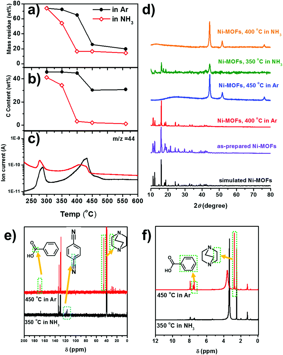 | ||
| Fig. 2 (a) The weight loss profile and (b) the carbon content of the Ni-MOF derived catalysts obtained at different temperatures. (c) CO2 in the escaped gas detected by online MS during the decomposition of the Ni-MOF in Ar and NH3. (d) XRD patterns of Ni-MOF derived catalysts under various conditions as noted in the figure. The simulated M2(bdc)2(ted) structure is obtained from CCDC 66186538 (e) 13C and (f) 1H NMR spectra of the volatile organic solids obtained by the decomposition of the Ni-MOF. The peaks at δ = 40.5 in 13C NMR and δ = 2.50 in 1H NMR are ascribed to the (CD3)2SO (d-DMSO) solvent. | ||
Therefore, the high HER activity of the Ni–NH3 sample originates from the thin N-doped carbon coating layer.29,34 In fact, the promotion of the catalytic performance by the thin N-doped carbon layer has also been reported for a number of transition metals and the application is also limited to the HER.14,34–37 The theoretical calculation suggests that the thin carbon layer could modulate the electronic structure of the encapsulated metal, leading to optimized binding energy to the catalytic intermediates.34,35 So the excellent HER performance of the MOF-derived Ni catalyst is directly associated with the drastic carbon removal effect of NH3. Next, we will elucidate the carbon removal mechanism of NH3 and further improve the HER performance based on the mechanistic understanding.
As a first step in the mechanistic study, we replace the 20%NH3–80%Ar gas by 20%H2–80%Ar in the pyrolysis process. Although H2 is usually considered to be a reductive atmosphere, the elemental analysis result (shown in Table S1, ESI†) indicates that the reaction between H2 gas and the ligand is not sufficient in our case and its carbon removal effect is also limited. Thus, there is little change in morphology and performance for the HER (see TEM images and LSV curves in Fig. S7, ESI†) between catalysts heated in H2 and in Ar. Another comparative experiment is carried out by further heating the Ni–Ar sample in a 20%NH3–80%Ar atmosphere for 1 h. Here the composition, structure and HER performance (shown in Fig. S7, ESI†) of the obtained sample (Ni–Ar–NH3) are also very similar to those of Ni–Ar. Thus, the carbon removal effect of NH3 must be due to the interaction of NH3 with the Ni-MOF during the thermal decomposition process, rather than the direct etching of carbon.
To elucidate the interaction of NH3 with the Ni-MOF during thermal decomposition, we carry out a comprehensive analysis on the decomposition products of the Ni-MOF. The decomposition of the Ni-MOF yields a solid residue (i.e. the MOF-derived catalyst) and some volatile species. The volatile species are composed of gaseous species which are directly escaped and some volatile organic solids which are deposited in the cooler downstream region. The weight losses, compositions and XRD patterns of the solid residues obtained at different temperatures in 20%NH3 and in pure Ar are shown in Fig. 2a, b and d. In an Ar atmosphere, the Ni-MOF retains the framework structure up to 400 °C and metallic Ni with ∼30 wt% C is obtained at 450 °C, as indicated by the XRD pattern. Higher treatment temperature does not significantly reduce the weight loss and the C/Ni ratio. In an NH3 atmosphere, metallic Ni already starts to emerge at 350 °C, accompanied by a reduced C/Ni ratio. This suggests that NH3 may reduce the decomposition temperature of the Ni-MOF by removing the organic ligands. At 400 °C, the Ni-MOF is completed converted to Ni nanoparticles with very low carbon content. This suggests that NH3 may reduce the decomposition temperature of the Ni-MOF by removing the organic ligands.
To understand how NH3 facilitates ligand removal, the escaped gases during thermal decomposition are analysed by online mass spectroscopy (MS). Except for the carrying gases (Ar and NH3), CO2 (m/z = 44) is clearly detected (Fig. 2c). In both Ar and NH3 atmospheres, the CO2 signal starts to increase at ∼350 °C and the peak temperatures are 430 °C and 415 °C, respectively. The CO2 signal appears concomitantly with the m/z = 78 and m/z = 52 signals, which are attributed to the benzene ring and it fragments (C4H4) (Fig. S8, ESI†). Clearly, the above MS signals are due to the decomposition of the BDC ligand. However, the decomposition temperature is similar in both atmospheres. More intriguingly, in the NH3 atmosphere, the relative intensity of CO2 (with respect to the Ar signal) is even lower than that in the Ar atmosphere.
The organic solids deposited in the cooler, downstream region of the tube furnace, which are due to the decomposition of the organic ligands, are soluble in dimethylsulfoxide (DMSO). The 13C and 1H nuclear magnetic resonance (NMR) spectra of the organic solids dissolved in d-DMSO are shown in Fig. 2e and f respectively. In the solid organic residue obtained at 450 °C in Ar, benzoic acid (7.92, 7.61 and 7.52 ppm in the 1H NMR spectrum and 167.8, 130.2, 129.7, 128.6 ppm in the 13C NMR spectrum, respectively)39 and the methylene in the TED ligand (2.78 ppm in the 1H NMR spectrum and 45.6 ppm in the 13C NMR spectrum, respectively)40 can be identified. Clearly, the benzoic acid must come from the decarboxylation of the BDC ligand, which is in very good agreement with the CO2 detected by the online MS (Fig. 2c). Therefore, we can conclude that in Ar the organic ligands (BDC and TED) are mainly removed as entire molecules or with only slight structural modifications (i.e. decarboxylation of BDC).
Organic solids can already be obtained at 350 °C in NH3. In addition to the benzoic acid, terephthalonitrile is also found, as suggested by the peaks at 118.0 and 116.2 ppm in the 13C NMR spectra.41 The formation of the cyanide group is a classic nucleophilic attack of NH3 on the carboxylic group followed by H2O elimination.42,43 The formation of terephthalonitrile also reduces CO2 formation, which is also in agreement with online MS results (Fig. 2c). There is also no signal corresponding to TED in 13C and 1H NMR spectra. NH3 may induce a ring-open reaction of TED via ammonolysis, which is the inverse reaction of the synthesis reaction of TED by NH3 elimination from ethylenediamine and piperazine.44,45 The NMR characterization of the organic solids obtained in NH3 clearly suggests that NH3 may induce fragmentation of the organic ligands through cyanation of the BDC ligand and ammonolysis of the TED ligand.
With the above knowledge on the different decomposition mechanisms in NH3 and Ar, now we can understand how NH3 can assist the carbon removal (Fig. 3). Generally, the thermal decomposition of MOFs involves dissociation of the metal–ligand (M–L) bonds and carbonization of the organic ligands. The dissociation of the M–L bonds will facilitate the leaving of the organic ligands and reduction of the carbon content in the obtained catalysts. Due to the strong M–L bonds in this Ni-MOF, as inferred by its high thermal stability up to 400 °C in Ar, sufficiently high temperature is required for M–L bond dissociation. However, at high temperature, carbonization of the organic ligands will also occur. As a result, there will be significant overlap of the temperature region for M–L bond dissociation and carbonization of the ligands. The decomposition in Ar is a purely thermally controlled process. In this case, it is difficult to reduce the carbon content as M–L dissociation and carbonization will occur simultaneously.
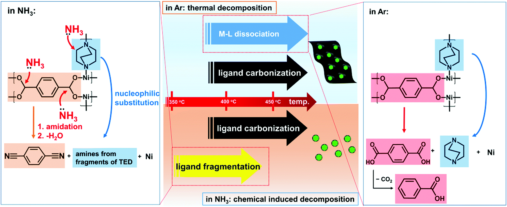 | ||
| Fig. 3 Different decomposition mechanisms of the Ni-MOF in Ar and NH3. In Ar, the decomposition is dominated by the dissociation of the M–L bonds. This step requires relatively high temperature and occurs parallel to the carbonization of the organic ligands, resulting in a high residual carbon content. NH3 can induce ligand fragmentation through the ammonolysis reactions as noted in the figure. In this case, ligand removal occurs well below the ligand carbonization temperature, which results in encapsulation of Ni particles in thin layers of N-doped carbon, the desired structure for the HER. | ||
However, NH3 can induce fragmentation of the organic ligands to generate more volatile species. As a result, the fragmentized ligands can be removed at much lower temperature, which no longer overlapped with that for carbonization of the ligands. As shown above, fragmentation of the ligands already occurs at 350 °C in NH3 where the Ni-MOF remains very stable in Ar. In our work, the decomposition is carried out at 450 °C. The organic ligands are already largely removed well below this temperature. Thus, the chemical induced fragmentation effect of NH3 allows removal of the organic ligands well before their carbonization, which is critical for efficient carbon removal and obtaining the desired structure (thin carbon layers on Ni nanoparticles) for HER applications.
Here a MOF-derived catalyst with excellent HER performance can be obtained at only 450 °C, which is only slightly above the decomposition threshold of the Ni-MOF. Typically, electrocatalysts derived by the thermal decomposition of MOFs require much higher temperature (mostly above 700 °C),7,20 as sufficiently high temperature is required to obtain a carbon structure with good electrical conductivity, which is essential for electrocatalysis. However, high temperature will cause aggregation of the metal species, which means a loss of catalytically active sites. Here the unique fragmentation effect of NH3 allows complete decomposition of the organic ligands at much lower temperature compared to that in an inert atmosphere, which is highly favourable for enhancing the HER performance of the MOF-derived catalysts.
According to the above mechanism, a less stable framework will further reduce the decomposition temperature and improve the performance of the obtained metal catalyst. The layer-pillar structure of the Ni-MOF used in this work also has isostructures based on other divalent transition metals such as Co, Cu and Zn.28,46,47 In our previous study, we found that isostructural Co-MOFs exhibit lower thermal stability compared to Ni-MOFs (Fig. S9, ESI†).38,48 Here we show that the HER performance of the MOF-derived catalyst can be further improved by low level Co substitution in the Ni-MOFs.
The Co substituted Ni-MOF Ni2−2xCo2x(BDC)2(TED) (designated as Ni1−xCox-MOF, where x is the fraction of Co substitution) can be readily prepared by the same hydrothermal synthesis using mixtures of Ni and Co nitrates. When the Ni0.9Co0.1-MOF sample is decomposed in 20%NH3–80%Ar flow at 450 °C, the obtained catalyst (Ni0.9Co0.1–NH3) is composed of Ni90Co10 alloy nanoparticles encapsulated in N-doped thin carbon layers, as suggested by the TEM and corresponding SAED, XRD and XPS results (Fig. 4a and Fig. S10–S12, ESI†). Elemental analysis suggests that the carbon content is 4.50 wt% and the N/C ratio reaches 0.41.
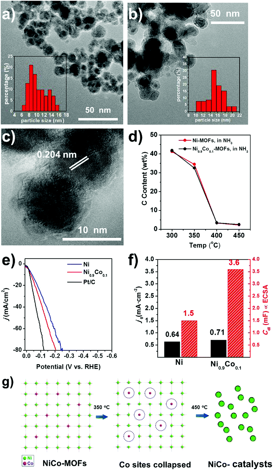 | ||
| Fig. 4 TEM images of (a) Ni0.9Co0.1–NH3 and (b) Ni–NH3 with the distributions of particle sizes shown in the inset. (c) HRTEM image of Ni0.9Co0.1–NH3. (d) The carbon contents of the Ni0.9Co0.1–NH3 and Ni–NH3 catalysts obtained at different temperatures. (e) Linear polarization curves of Ni–NH3, Ni0.9Co0.1–NH3, and Pt/C catalysts in 1 M KOH solution. (f) The exchange current density j0 and the double layer capacitance (Cdl) of Ni–NH3 and Ni0.9Co0.1–NH3. (g) Schematic illustration of the destabilization effect due to Co substitution. Decomposition is started at the Co sites due to the weaker Co–ligand bonding, resulting in smaller, more uniform particles of the derived catalyst. | ||
The general structural feature is similar to that of Ni–NH3, while Ni0.9Co0.1–NH3 has smaller and more uniform particles (∼10 nm in diameter) compared to those of Ni–NH3 (∼15 nm in diameter), as shown by the TEM images in Fig. 4a–c. And from the N2 adsorption curves shown in Fig. S4 (ESI†), the physical surface area of Ni0.9Co0.1–NH3 (60 m2 g−1) is more than twice that of Ni–NH3, due to not only the increased carbon content but also the diminished particle size.
The HER performance the Ni0.9Co0.1–NH3 sample is further improved compared to that of Ni–NH3. Even lower overpotentials (η10 = 36 mV and η20 = 58 mV, respectively) are observed, which are close to that of the commercial Pt/C catalyst with 20 wt% Pt (shown in Fig. 4e), implying very high HER activity in alkaline media. In addition, a low Tafel slope of only 41 mV decade−1 is obtained (Fig. 5d), which suggests a nearly full Heyrovsky mechanism for the HER, i.e. the HER rate is determined by both discharge of H2O and desorption of H from the catalyst surface. The performance of the MOF-derived Ni–Co catalyst is superior to the most noble-metal-free HER catalysts reported recently, as shown in Table S3 (ESI†). The Ni0.9Co0.1–NH3 catalyst also exhibits excellent stability. As shown in Fig. 5a, the overpotential of the catalyst remains only at 70 mV in continuous electrolysis at 20 mA cm−2 for 15 hours. In the first 6 h of this period quantification of the H2 evolved by chromatography suggests nearly 100% Faradic efficiency (Fig. S14, ESI†). Despite the large fluctuation of the potential due to the fast bubble generation, the potential remains highly stable at a high current density of 200 mA cm−2 (shown in Fig. 5b).
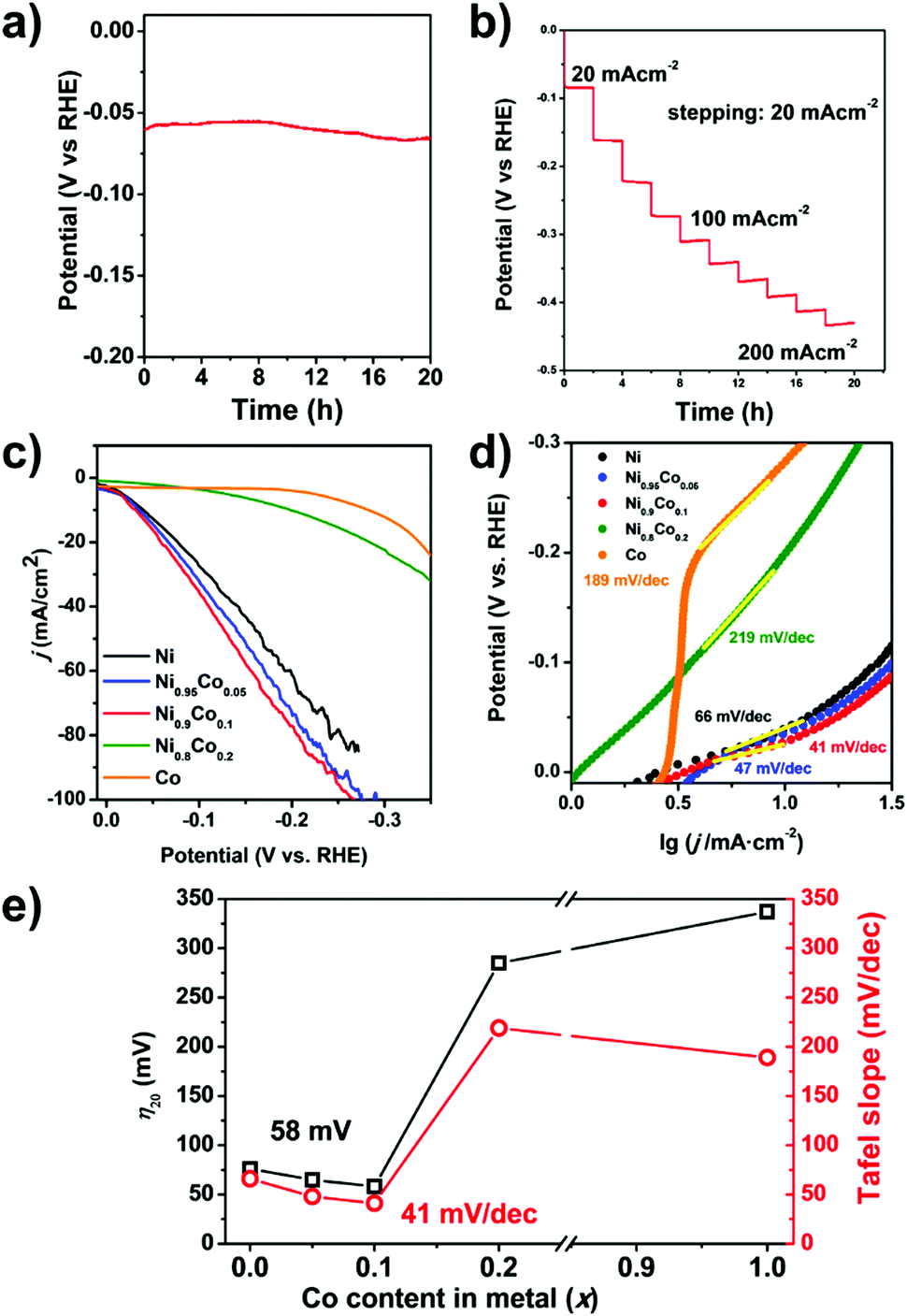 | ||
| Fig. 5 (a) Variation in the potential during continuous electrolysis for 20 h at 20 mA cm−2. (b) Galvanostatic measurements for Ni0.9Co0.1–NH3 at different current densities up to 200 mA cm−2. (c) Linear polarization curves and (d) Tafel plots of Ni–NH3, Ni0.95Co0.05–NH3, Ni0.9Co0.1–NH3, Ni0.8Co0.2–NH3, and Co–NH3 catalysts in 1 M KOH solution. (e) The key figures of merit (overpotential at 20 mA cm−2 (η20) and the Tafel slope) for the HER for the Ni1−xCox–NH3 catalysts. | ||
We assemble an alkaline electrolyzer using Ni0.9Co0.1–NH3 as the HER catalyst and another MOF-derived NiFe-based catalyst that we previously developed as the catalyst for the oxygen evolution reaction.49 The polarization curve of the two-electrode electrolyzer is shown in Fig. 6b, which shows a low voltage of only 1.61 V at a current density of 10 mA cm−2. The current density is stable with a low voltage of 1.6 V for more than 12 h, as shown in Fig. 6c, indicating high stability of both the HER and OER catalysts. The electrolysis cell can be driven by a commercial polycrystalline silicon solar cell (Fig. 6a). With a Xe lamp irradiation of 100 mW cm−2 (AM 1.5 conditions), the cell works with a voltage of 2.0 V and a current density of 81 mA cm−2, respectively. The corresponding hydrogen production rate reaches 3.0 mmol h−1 cm−2 with an overall solar-to-hydrogen energy efficiency of 7.9%. Considering that the efficiency of the commercial polycrystalline solar cell here is only moderate (12.7% under AM 1.5 conditions), the STH efficiency could be further improved by using more efficient solar cells. For the electrolysis cell, an overall electrolysis efficiency of 62.1% at 81 mA cm−2 is achieved. The efficiency loss due to the overpotential on the HER electrode is only 10.4%, indicating that the Ni0.9Co0.1–NH3 HER catalyst is sufficiently active to replace a Pt based HER catalyst for water electrolysis.
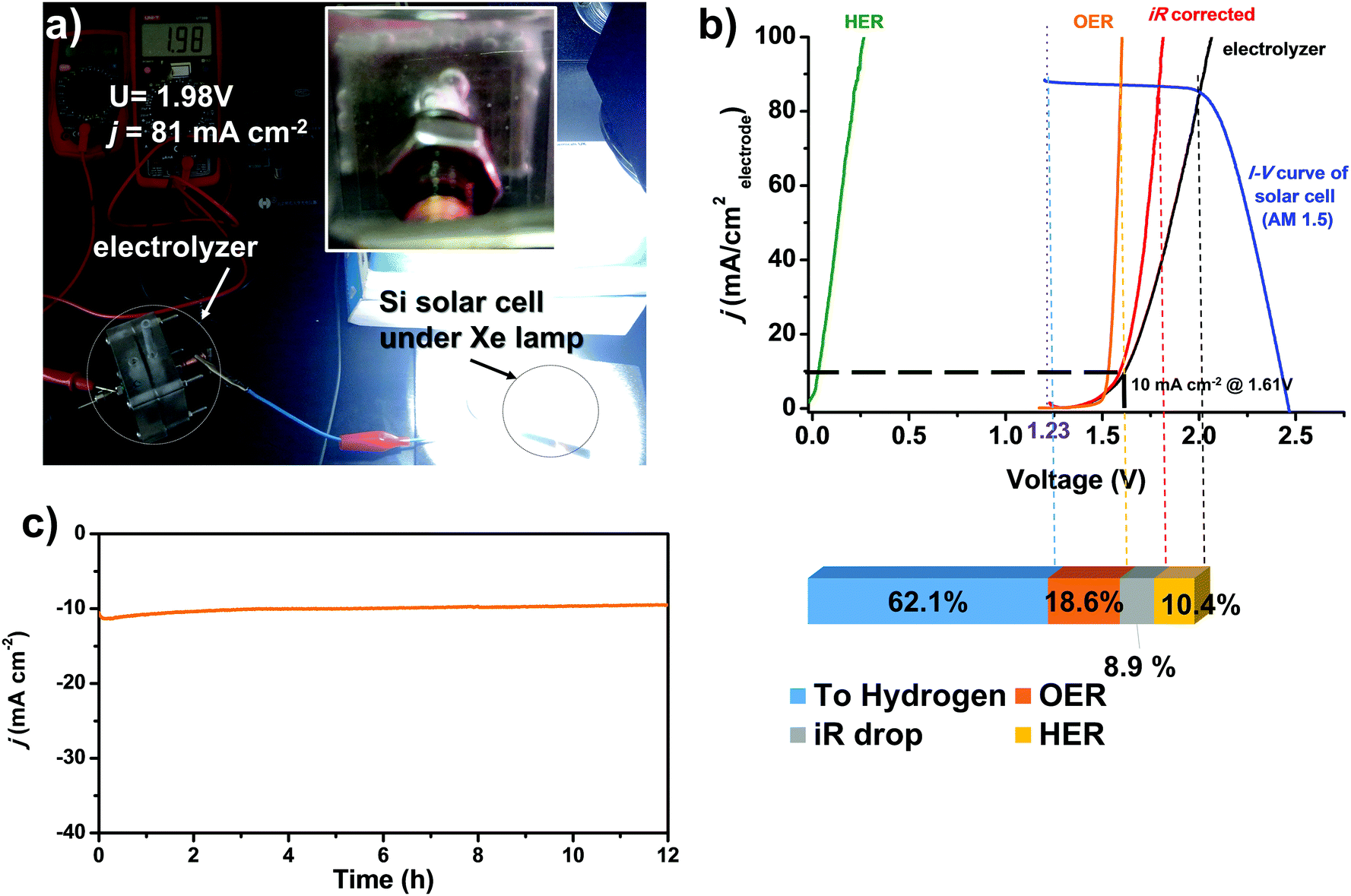 | ||
| Fig. 6 (a) Photograph of the alkaline water electrolyzer using Ni0.9Co0.1–NH3 as the HER catalyst and a NiFe based OER catalyst powered by a commercial polycrystalline Si solar cell under 100 W cm−2 Xe lamp irradiation. The H2 bubbles are generated vigorously, as shown in the inset. (b) The electrolyzer polarization curve and the j–V curve of the Si solar cell. The energy loss of each component is also shown. (c) The j–t curve of the electrolyzer at a constant input voltage of 1.6 V. | ||
The effect of the Co substitution level is studied, which suggests that only a low Co substitution level is required to promote the HER performance. In Fig. 5c–e, the overpotentials and Tafel slopes of Ni1−xCox–NH3 catalysts with different Co substitution levels are compared. A slight yet clear improvement is observed when the Co substitution level increases from 0 to 0.1. Further increasing the Co fraction causes rapid deterioration of the performance. The performance of the Ni0.8Co0.2–NH3 catalyst is even poorer than that of the Ni–NH3 sample and the Co–NH3 sample barely shows any catalytic activity for the HER.
The effect of Co doping is very intriguing. As a single metal catalyst, Co is less active for the HER compared to Ni.50–54 Although alloy formation may modify the electronic structure and promote the HER performance, such an effect usually appears at a definite optimal composition. In most cases, the compositions of both components are substantial.50,54 Here the best HER performance is obtained at very low Co substitution (<10%) and deteriorates almost monotonically with increasing Co content very rapidly. This indicates that it is unlikely that trace Co doping may significantly modify the electronic structure of Ni and promote the HER performance. Indeed, there have been no definite evidence to show that Co doping may promote the intrinsic HER activity of Ni. Although good HER catalysts based on Ni–Co alloys have been reported, the Ni/Co ratio in these catalysts varies diversely.34,52
We believe that the promotion effect of Co substitution is mainly due to the destabilization of the framework, which yields smaller, more uniform particles after thermal decomposition. Smaller particles will enhance the ECSA value. ECSA is (Cdl) proportional to the double layer capacitance in the electrode–electrolyte interface, which can be quantitatively evaluated from the cyclic voltammetry curves with different potential scanning rates in the non-Faradaic potential region (Fig. S15, ESI†). Compared to the Ni–NH3 sample, the ECSA of the Ni0.9Co0.1–NH3 sample is more than doubled, while the exchange current density j0 obtained from the intercept of the Tafel plots increases only by 11% (Fig. 4f). This is another piece of evidence that the enhanced HER performance is mainly due to the enhanced ECSA rather than the higher intrinsic activity.
The enhanced ECSA is in agreement with the smaller particle size of the Ni0.9Co0.1–NH3 sample, which is mainly attributed to the destabilization of the framework due to Co doping. The isostructural Co-MOF has intrinsically lower thermal stability compared to that of the Ni-MOF, as shown in the TGA curves in Ar (Fig. S9, ESI†), indicating weaker Co–ligand bonding. Therefore, Co doping introduces some weaker bonding sites into the framework, at which decomposition is initiated during the temperature ramping process, as schematically illustrated in Fig. 4g. Indeed, at the threshold decomposition temperature in NH3 (350 °C), Co substitution results in a higher weight loss and lower carbon content, which can be attributed to the more favorable decomposition at the Co sites. The homogeneously distributed weaker bonding Co sites provide nucleation sites for the subsequent growth of the Ni particles when the framework is completely decomposed at higher temperature, resulting in smaller, more homogeneous Ni0.9Co0.1 particles.
Conclusions
The decomposition mechanisms of a Ni-MOF are significantly different in Ar and in NH3, which yield Ni based HER catalysts with distinct structures and performances. In thermal decomposition in Ar, the dissociation of the metal–ligand bonds and carbonization of the organic ligands occur simultaneously in the same temperature region. The obtained Ni catalyst contains a high content of residual carbon and only exhibits very poor HER performance. On the other hand, NH3 can induce fragmentation of the ligands and effectively remove the organic ligands well below the carbonization temperature, which yields Ni nanoparticles encapsulated in thin layers of N-doped carbon with excellent HER performance. Based on the above mechanistic understanding, we show that low levels of Co doping in the Ni-MOF may further improve the HER performance of the obtained catalyst, which is mainly attributed to the destabilization of the framework by Co doping. The chemical induced decomposition approach reported in this work offers new possibilities for preparing MOF-derived functional materials.Conflicts of interest
There are no conflicts to be declared by the authors.Acknowledgements
The authors acknowledge the financial support from the National Natural Science Foundation of China (No. 51431001, 51771002, U1607126 and 21321001) and the Beijing Municipal Commission of Science and Technology (Z17110000091702).References
- Y. V. Kaneti, J. Tang, R. R. Salunkhe, X. C. Jiang, A. B. Yu, K. C. W. Wu and Y. Yamauchi, Adv. Mater., 2017, 29, 40 Search PubMed.
- H. G. Zhang, H. Osgood, X. H. Xie, Y. Y. Shao and G. Wu, Nano Energy, 2017, 31, 331–350 CrossRef.
- W. Wang, X. Xu, W. Zhou and Z. Shao, Adv. Sci., 2017, 4, 1600371 CrossRef PubMed.
- S. Ma, G. A. Goenaga, A. V. Call and D. J. Liu, Chem. – Eur. J., 2011, 17, 2063–2067 CrossRef PubMed.
- X. Wang, J. Zhou, H. Fu, W. Li, X. Fan, G. Xin, J. Zheng and X. Li, J. Mater. Chem. A, 2014, 2, 14064–14070 CAS.
- A. Mahmood, W. Guo, H. Tabassum and R. Zou, Adv. Energy Mater., 2016, 6, 1600423 CrossRef.
- Z. Shi, Y. Wang, H. Lin, H. Zhang, M. Shen, S. Xie, Y. Zhang, Q. Gao and Y. Tang, J. Mater. Chem. A, 2016, 4, 6006–6013 CAS.
- Z. X. Song, N. C. Cheng, A. Lushington and X. L. Sun, Catalysts, 2016, 6, 19 CrossRef.
- H. L. Jiang, B. Liu, Y. Q. Lan, K. Kuratani, T. Akita, H. Shioyama, F. Zong and Q. Xu, J. Am. Chem. Soc., 2011, 133, 11854–11857 CrossRef PubMed.
- M. Hu, J. Reboul, S. Furukawa, N. L. Torad, Q. Ji, P. Srinivasu, K. Ariga, S. Kitagawa and Y. Yamauchi, J. Am. Chem. Soc., 2012, 134, 2864–2867 CrossRef CAS PubMed.
- K. Shen, X. Chen, J. Chen and Y. Li, ACS Catal., 2016, 6, 5887–5903 CrossRef.
- H. D. Mai, K. Rafiq and H. Yoo, Chemistry, 2016, 23, 5631–5651 CrossRef PubMed.
- D. Zhao, J. L. Shui, L. R. Grabstanowicz, C. Chen, S. M. Commet, T. Xu, J. Lu and D. J. Liu, Adv. Mater., 2014, 26, 1093–1097 CrossRef PubMed.
- H. B. Wu, B. Y. Xia, L. Yu, X. Y. Yu and X. W. Lou, Nat. Commun., 2015, 6, 6512 CrossRef CAS PubMed.
- Y. J. Tang, M. R. Gao, C. H. Liu, S. L. Li, H. L. Jiang, Y. Q. Lan, M. Han and S. H. Yu, Angew. Chem., Int. Ed., 2015, 54, 12928–12932 CrossRef CAS PubMed.
- Y. Z. Chen, C. Wang, Z. Y. Wu, Y. Xiong, Q. Xu, S. H. Yu and H. L. Jiang, Adv. Mater., 2015, 27, 5010–5016 CrossRef PubMed.
- X. Wang, X. Fan, H. Lin, H. Fu, T. Wang, J. Zheng and X. Li, RSC Adv., 2016, 6, 37965–37973 RSC.
- X. Wang, H. Zhang, H. Lin, S. Gupta, C. Wang, Z. Tao, H. Fu, T. Wang, J. Zheng, G. Wu and X. Li, Nano Energy, 2016, 25, 110–119 CrossRef.
- W. Xia, R. Zou, L. An, D. Xia and S. Guo, Energy Environ. Sci., 2015, 8, 568–576 CAS.
- Y. Xu, W. Tu, B. Zhang, S. Yin, Y. Huang, M. Kraft and R. Xu, Adv. Mater., 2017, 29, 1605957 CrossRef PubMed.
- J. S. Luo, J. H. Im, M. T. Mayer, M. Schreier, M. K. Nazeeruddin, N. G. Park, S. D. Tilley, H. J. Fan and M. Gratzel, Science, 2014, 345, 1593–1596 CrossRef CAS PubMed.
- P. C. K. Vesborg, B. Seger and I. Chorkendorff, J. Phys. Chem. Lett., 2015, 6, 951–957 CrossRef CAS PubMed.
- H. Zhang, X. Zheng, X. Tian, Y. Liu and X. Li, Prog. Nat. Sci.: Mater. Int., 2017, 27, 50–57 CrossRef CAS.
- B. Zhang and Y. Wu, Prog. Nat. Sci.: Mater. Int., 2017, 27, 21–33 CrossRef CAS.
- V. R. Stamenkovic, D. Strmcnik, P. P. Lopes and N. M. Markovic, Nat. Mater., 2016, 16, 57–69 CrossRef PubMed.
- D. Strmcnik, P. P. Lopes, B. Genorio, V. R. Stamenkovic and N. M. Markovic, Nano Energy, 2016, 29, 29–36 CrossRef CAS.
- C. G. Morales-Guio, L. A. Stern and X. Hu, Chem. Soc. Rev., 2014, 43, 6555–6569 RSC.
- M. Jahan, Z. Liu and K. P. Loh, Adv. Funct. Mater., 2013, 23, 5363–5372 CrossRef CAS.
- T. Wang, Q. Zhou, X. Wang, J. Zheng and X. Li, J. Mater. Chem. A, 2015, 3, 16435–16439 CAS.
- T. Fu, M. Wang, W. Cai, Y. Cui, F. Gao, L. Peng, W. Chen and W. Ding, ACS Catal., 2014, 4, 2536–2543 CrossRef CAS.
- Z. Zhao, H. Wu, H. He, X. Xu and Y. Jin, Adv. Funct. Mater., 2014, 24, 4698–4705 CrossRef CAS.
- B. Cao, G. M. Veith, J. C. Neuefeind, R. R. Adzic and P. G. Khalifah, J. Am. Chem. Soc., 2013, 135, 19186–19192 CrossRef CAS PubMed.
- H. Yan, C. Tian, L. Wang, A. Wu, M. Meng, L. Zhao and H. Fu, Angew. Chem., Int. Ed., 2015, 54, 6325–6329 CrossRef CAS PubMed.
- J. Deng, P. Ren, D. Deng and X. Bao, Angew. Chem., Int. Ed., 2015, 54, 2100–2104 CrossRef CAS PubMed.
- H. Zhang, Z. Ma, J. Duan, H. Liu, G. Liu, T. Wang, K. Chang, M. Li, L. Shi, X. Meng, K. Wu and J. Ye, ACS Nano, 2016, 10, 684–694 CrossRef CAS PubMed.
- J. Deng, P. Ren, D. Deng, L. Yu, F. Yang and X. Bao, Energy Environ. Sci., 2014, 7, 1919–1923 CAS.
- Y. Yang, Z. Lun, G. Xia, F. Zheng, M. He and Q. Chen, Energy Environ. Sci., 2015, 8, 3563–3571 CAS.
- H. Wang, J. Getzschmann, I. Senkovska and S. Kaskel, Microporous Mesoporous Mater., 2008, 116, 653–657 CrossRef CAS.
- K. Alagiri and K. R. Prabhu, Tetrahedron, 2011, 67, 8544–8551 CrossRef CAS.
- R. L. Benoit, D. Lefebvre and M. Frechette, Can. J. Chem.-Rev. Can. Chim., 1987, 65, 996–1001 CrossRef CAS.
- S.-L. Zhang and L. Huang, Org. Biomol. Chem., 2015, 13, 9963–9968 CAS.
- P. Oxley, M. W. Partridge, T. D. Robson and W. F. Short, J. Chem. Soc., 1946, 763–771, 10.1039/JR9460000763.
- A. Misono, T. Osa and S. Koda, Bull. Chem. Soc. Jpn., 1967, 40, 912–919 CrossRef CAS.
- Y. Wang, L. Guo, Y. Ling, Y. Liu, X. Li, H. Wu and P. Wu, Appl. Catal., A, 2010, 379, 45–53 CrossRef CAS.
- J. E. Wells, F. C. Wilhelm, J. F. White and N. K. Dicciani, Org. Process Res. Dev., 2016, 20, 1044–1052 CrossRef CAS.
- P. Maniam and N. Stock, Inorg. Chem., 2011, 50, 5085–5097 CrossRef CAS PubMed.
- C. R. Wade and M. Dinca, Dalton Trans., 2012, 41, 7931–7938 RSC.
- P. Song, Y. Li, B. He, J. Yang, J. Zheng and X. Li, Microporous Mesoporous Mater., 2011, 142, 208–213 CrossRef CAS.
- Z. Tao, T. Wang, X. Wang, J. Zheng and X. Li, ACS Appl. Mater. Interfaces, 2016, 8, 35390–35397 CAS.
- C. Lupi, A. Dell'Era and M. Pasquali, Int. J. Hydrogen Energy, 2009, 34, 2101–2106 CrossRef CAS.
- S. E. Fosdick, S. P. Berglund, C. B. Mullins and R. M. Crooks, ACS Catal., 2014, 4, 1332–1339 CrossRef CAS.
- C. C. L. McCrory, S. Jung, I. M. Ferrer, S. M. Chatman, J. C. Peters and T. F. Jaramillo, J. Am. Chem. Soc., 2015, 137, 4347–4357 CrossRef CAS PubMed.
- X. Liu, W. Liu, M. Ko, M. Park, M. G. Kim, P. Oh, S. Chae, S. Park, A. Casimir, G. Wu and J. Cho, Adv. Funct. Mater., 2015, 25, 5799–5808 CrossRef CAS.
- S. H. Hong, S. H. Ahn, I. Choi, S. G. Pyo, H.-J. Kim, J. H. Jang and S.-K. Kim, Appl. Surf. Sci., 2014, 307, 146–152 CrossRef CAS.
Footnote |
| † Electronic supplementary information (ESI) available: Experimental details and additional figures and tables. See DOI: 10.1039/c7nh00193b |
| This journal is © The Royal Society of Chemistry 2018 |