Growth of high-quality covalent organic framework nanosheets at the interface of two miscible organic solvents†
Yang
Li
,
Meicheng
Zhang
,
Xinghua
Guo
,
Rui
Wen
,
Xing
Li
,
Xiaofeng
Li
,
Shoujian
Li
 * and
Lijian
Ma
 *
*
College of Chemistry, Sichuan University, Key Laboratory of Radiation Physics & Technology, Ministry of Education, No. 29 Wangjiang Road, Chengdu, 610064, P. R. China. E-mail: sjli000616@scu.edu.cn; ma.lj@hotmail.com; Fax: +86-028-8541 2907; Tel: +86-028-8541 2329
First published on 15th January 2018
Abstract
Stronger covalent bonds between monomers, relatively more complex growth processes (polymerization, crystallization, assembly, etc.) and π–π stacking interactions between adjacent layers make it extremely difficult to obtain highly ordered crystalline 2D covalent organic framework (COF) nanosheets. So more effective solutions have to be developed to push the methods reported so far beyond their inherent limitations. Herein, we report the first example of growing high-quality 2D COF nanosheets (NS-COF) at the interface of two miscible organic solvents. The novel approach, which is named as a buffering interlayer interface (BII) method, can be achieved by simply adding a low-density solvent interlayer, as a buffer layer, between the two miscible main solvents based on the self-propelled directed motion of the interface driven by the density differences among the solvents involved. The as-synthesized NS-COF exhibits a super-large size and a relatively regular shape with a smooth surface, which have not been observed before. The proposed strategy offers a facile and effective approach for growing well-structured 2D COF nanosheets and also other kinds of nanosheets.
Conceptual insightsA liquid–liquid interface method possesses extensive adaptability and substantial practical value in the construction of 2D nanosheets. However, only water–organic solvent systems, so far as we know, have been employed in the construction of 2D COF nanosheets. But in fact, almost all the monomers used for the synthesis of 2D COFs are organic molecules, which are normally soluble in organic solvents. So it inspires us to envision that growing 2D COF nanosheets at organic–organic solvent interfaces might be a feasible approach. Unfortunately, although the organic solvents that could dissolve the selected monomers are easily available, it is hard to meet the immiscibility requirements of the two preselected solvents. So we have to make one more choice to grow 2D COF nanosheets at the interface of the two miscible organic solvents. Herein, we report the first example of growing high-quality 2D COF nanosheets (NS-COF) at the interface of two miscible organic solvents. The applicability of the proposed method was also verified using different monomers and different solvents. Our strategy offers a new, facile and effective approach for the growth of 2D well-structured COF nanosheets and/or other kinds of nanosheets. |
Introduction
Two-dimensional covalent organic frameworks (2D COFs) are one such class of layered crystalline polymeric materials which have shown great promising applications in gas adsorption,1–5 metal ion separation and recovery,6–8 energy storage,9–12 catalysis,13–15 chemical sensing,16–18etc. Compared with graphene or other inorganic 2D nanomaterials, 2D layered COFs possess some competitive advantages, such as a wide variety of optional monomers and flexible topological connectivity of monomers, leading to tunable properties of the 2D materials.19–21 However, due to the relatively complicated growth process involving polymerization, crystallization, assembly, etc., it still remains a great challenge to prepare highly-ordered and well-structured 2D COF nanosheets so far.In general, the preparation methods of 2D COF nanosheets reported so far can be divided into two categories: top-down and bottom-up. The “top-down” strategy refers to the pre-synthesis of stacked or 3D bulk COFs under certain conditions, and then exfoliation of the 3D ones into 2D nanosheets by ultrasonic stripping,22–24 solvent immersion,25 mechanical grinding,26–29 physical milling,30 chemical intercalation,31,32etc., and it is difficult to control the proportion, the thickness and the size distribution of the exfoliated 2D nanosheets because the morphologies of the stripped nanosheets are closely related to those of their parent bulk COFs (mostly spherical or irregular in shape). The “bottom-up” strategy is expected to build 2D COF nanosheets directly from chosen monomers. To overcome the π–π stacking interactions, non-planar monomers33,34 or charged monomers35 were employed to realize the construction of 2D COF nanosheets. However, this would actually limit alternative monomers available to researchers. Another effective method is to prepare a single COF layer on a solid surface. But ultra-high vacuum conditions are usually required and especially it is difficult to separate the COF layer from the substrate.36–38 Recently, significant progress has been achieved in growing 2D COF nanosheets at air–water or water–organic solvent interfaces.39–43 However, in fact, almost all the monomers for growth of both 2D and 3D COFs are organic molecules, and their solubility in water is limited, which could be the biggest hurdle in popularization of these methods.
Therefore, we tried to find two immiscible organic solvents with good solubility to the two selected organic monomers, respectively, and grow 2D COF nanosheets at the liquid–liquid interface. But unfortunately, although the organic solvents that could dissolve the selected monomers are easily available, it is hard to meet the immiscibility requirements of the two preselected solvents. So we have to make one more choice to grow 2D COF nanosheets at the interface of the two miscible organic solvents. It was conceived that by adding a low-density solvent as a buffer interlayer between the two miscible solvents to stave off the mutual dissolution and maintain the interface between the two main solvents, we could achieve our goal on the basis of the self-propelled motion of the interface driven by the density differences of the solvents involved.
For the purpose of verifying this strategy, an aldehyde–amine condensation reaction is employed to grow salicylideneimine-functionalized 2D COF nanosheets in this work. Typically, methylene chloride and methylene chloride–DMF mixed solvents are used to dissolve 1,3,5-triformylphloroglucinol (TFP) and dihydroxybenzidine (DHBD) respectively. Importantly, acetic acid is chosen as both a catalyst and a buffer solvent. The synthesis process is as follows.
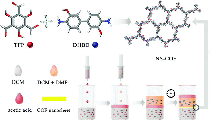
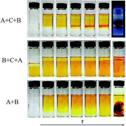
A schematic diagram of the growing process of 2D layered COFs is shown in Scheme 1. Firstly, a certain amount of TFP was dissolved in 80 mL of methylene chloride (1.325 g mL−1 at 25 °C) to give an aldehyde solution (A); then 20 mL of 12 M acetic acid solution (buffer C, 1.06 g mL−1 at 25 °C) was added slowly until the surface of A was completely covered. An amine solution (B) was prepared by dissolving a certain amount of DHBD in a mixed solution of 80 mL of dichloromethane and 20 mL of N,N-dimethylformamide (DMF, 0.944 g mL−1 at 25 °C). Next, solution B was added dropwise to the surface of buffer C. The preparation process with the above adding order of the three starting solutions is, for convenience, named A + C + B, as shown in Fig. 1. Because the density of B is greater than that of C, the interface between them will gradually move down; this means that solution B will permeate down slowly through the buffer C layer to the surface of solution A. The front amine monomers (DHBD) in solution B will rapidly react with the aldehydes (TFP) at the surface of solution A to form COF nanosheets under the catalysis of acetic acid. The newly generated nanosheets could also act as a “buffer layer” for retarding the diffusion of the amines towards solution A (see Fig. 1). As a consequence, the reaction rate between TFP and DHBD is greatly postponed, which is more conducive to the orderly self-assembly of 2D COF nanosheets from the building blocks. In addition, the permeating rate of solution B into A will be lowered down because the density of solution B is slightly smaller than that of A. All these factors would contribute to the growth of 2D COF nanosheets with high quality and prevention of unbounded layer stacking. After a period of time, the product was collected and washed thoroughly with dichloromethane, ethanol, acetone and DMF in turn, and put aside for further investigation. In the above process, density differences of the solvents used and addition of acetic acid as a “buffer layer” are the two critical factors that ensure the growth of COF nanosheets with high quality at the organic–organic interface. It is noteworthy that if A and B were added in reverse order the ternary solvent system would be completely homogeneous instead of hierarchical (see Fig. 1, B + C + A). In addition, there is no obvious interface between the two main solvents (A and B) without the addition of an acetic acid intermediate layer (see Fig. 1, A + B). Optical images of different preparation processes with different adding sequences of the three starting solutions (solutions A, B and/or C) in our experiments are shown in Fig. 1.
Results and discussion
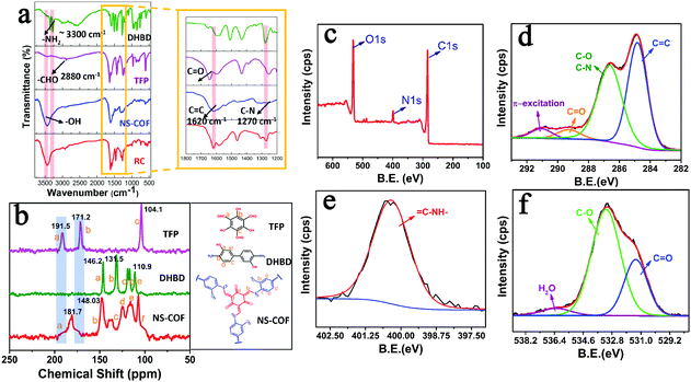
The formation of COF nanosheets (NS-COF) was assessed by FT-IR spectroscopy, confocal Raman spectroscopy, 13C cross-polarization magic-angle-spinning solid-state NMR spectroscopy, elemental analysis, X-ray photoelectron spectroscopy (XPS), etc. From the FT-IR spectra shown in Fig. 2a, it can be seen that the characteristic absorption peaks (–NH2 at ∼3300 cm−1, –CHO at ∼2880 cm−1) of the starting materials disappeared after the condensation reaction. Simultaneously, the formation of two new peaks at 1620 and 1270 cm−1 could be attributed to the vibrations of C![[double bond, length as m-dash]](https://www.rsc.org/images/entities/char_e001.gif) C and C
C and C![[double bond, length as m-dash]](https://www.rsc.org/images/entities/char_e001.gif) C–NH in the NS-COF.12,27,28 In addition, the FT-IR spectrum of the NS-COF was compared with that of the reference compound (RC, see the ESI,† Scheme S1 and Fig. S1), 2,4,6-tris[(phenylamino)methylene]cyclohexane-1,3,5-trione, freshly synthesized in this study. The very similar spectra suggested that both of them have the same structures. All these mentioned above could provide preliminary support for the successful formation of objective frameworks. Furthermore, the stretching vibrations of C
C–NH in the NS-COF.12,27,28 In addition, the FT-IR spectrum of the NS-COF was compared with that of the reference compound (RC, see the ESI,† Scheme S1 and Fig. S1), 2,4,6-tris[(phenylamino)methylene]cyclohexane-1,3,5-trione, freshly synthesized in this study. The very similar spectra suggested that both of them have the same structures. All these mentioned above could provide preliminary support for the successful formation of objective frameworks. Furthermore, the stretching vibrations of C![[double bond, length as m-dash]](https://www.rsc.org/images/entities/char_e001.gif) C are also observed at 1609 cm−1 in the laser Raman spectra of the NS-COF and RC (Fig. S2, ESI†),44 and in particular, the laser Raman spectrum of the NS-COF is observed to be reasonable matching with that of its reference compound, which is significantly consistent with the results of FT-IR analysis.
C are also observed at 1609 cm−1 in the laser Raman spectra of the NS-COF and RC (Fig. S2, ESI†),44 and in particular, the laser Raman spectrum of the NS-COF is observed to be reasonable matching with that of its reference compound, which is significantly consistent with the results of FT-IR analysis.
The 13C solid-state NMR spectra of TFP, DHBD and NS-COF are shown in Fig. 2b. The complete disappearance of the characteristic peaks at 191.5 and 171.2 ppm reveals the thorough consumption of TFP. The conspicuous, newly formed signal at 181.7 ppm could be ascribed to the formation of carbonyl carbon of the keto form in the as-synthesized NS-COF. The absence of TFP signals and the formation of carbonyl group provided persuasive evidence of the keto form structures in the NS-COF derived by tautomerism during the reaction process.12,27,28 Furthermore, the signal located at ∼148 ppm could be attributed to C![[double bond, length as m-dash]](https://www.rsc.org/images/entities/char_e001.gif) C–N, corresponding to the expected structure for the NS-COF, and the peaks from 100 to 130 ppm are caused mainly by the resonance absorption of carbons of the phenyl ring.
C–N, corresponding to the expected structure for the NS-COF, and the peaks from 100 to 130 ppm are caused mainly by the resonance absorption of carbons of the phenyl ring.
Elemental analysis (EA, Table S2, ESI†) showed that the observed contents of C/N/H were close to the calculated value. It is worth noting that the C (wt%) and N (wt%) are slightly lower than the theoretical predictions for a perfect target COF material. The differences may be ascribed to the formation of non-combustible carbon nitride byproducts during the process of the elemental analysis or the hygroscopic nature of the NS-COF.12
The XPS spectra of the NS-COF are shown in Fig. 2c–f. The C1s signal (Fig. 2d) of the NS-COF has four apparent peaks which are, respectively, attributed to C![[double bond, length as m-dash]](https://www.rsc.org/images/entities/char_e001.gif) C or C–C (284.8 eV), C–O and C–N (286.6 eV), C
C or C–C (284.8 eV), C–O and C–N (286.6 eV), C![[double bond, length as m-dash]](https://www.rsc.org/images/entities/char_e001.gif) O (289.2 eV) and π-excitation (291.2 eV).45,46 Generally, the π-excitation signal could be observed in all carbon compounds with double bonds, and it is usually located at ∼7 eV above the basic C1s peak.45,46 Therefore, the peak at 284.8 eV could be ascribed to the C
O (289.2 eV) and π-excitation (291.2 eV).45,46 Generally, the π-excitation signal could be observed in all carbon compounds with double bonds, and it is usually located at ∼7 eV above the basic C1s peak.45,46 Therefore, the peak at 284.8 eV could be ascribed to the C![[double bond, length as m-dash]](https://www.rsc.org/images/entities/char_e001.gif) C double bonds existing in the structure of the NS-COF. The N1s (Fig. 2e) signal of the NS-COF has only one peak with a binding energy of 400.4 eV, which can be attributed to the enamine nitrogen (C
C double bonds existing in the structure of the NS-COF. The N1s (Fig. 2e) signal of the NS-COF has only one peak with a binding energy of 400.4 eV, which can be attributed to the enamine nitrogen (C![[double bond, length as m-dash]](https://www.rsc.org/images/entities/char_e001.gif) C–NH–). The results are closely related to the microstructures of the final extended frameworks after imine–enamine tautomerism in the synthesis process of the NS-COF. Moreover, the O1s signal is shown in Fig. 2f. The peaks for C
C–NH–). The results are closely related to the microstructures of the final extended frameworks after imine–enamine tautomerism in the synthesis process of the NS-COF. Moreover, the O1s signal is shown in Fig. 2f. The peaks for C![[double bond, length as m-dash]](https://www.rsc.org/images/entities/char_e001.gif) O and C–OH species appearing at 531.3 eV and 533.2 eV, respectively, are also in accordance with the structures of the NS-COF.45,46 Quantitative analysis of the XPS data shows that the O (24 at%) was larger than its calculated value (17 at%), which might be caused by the existence of water molecules, corresponding to a water peak with a binding energy of 536.3 eV.47 All the results obtained from the above spectroscopic data, combined with CHN elemental analysis, strongly verify the formation of NS-COF with the desired microstructures.
O and C–OH species appearing at 531.3 eV and 533.2 eV, respectively, are also in accordance with the structures of the NS-COF.45,46 Quantitative analysis of the XPS data shows that the O (24 at%) was larger than its calculated value (17 at%), which might be caused by the existence of water molecules, corresponding to a water peak with a binding energy of 536.3 eV.47 All the results obtained from the above spectroscopic data, combined with CHN elemental analysis, strongly verify the formation of NS-COF with the desired microstructures.
On the other hand, the stacking modes of the NS-COF were studied by powder X-ray diffraction (see Fig. S3, ESI†). Interestingly, the as-synthesized NS-COF does not show any diffraction peak before 5 degrees (2θ) (see Fig. S4, ESI†). This means that the multilayers of the COF sheet are stacked neither with an eclipsed geometry (AA stacking sequence) nor with a staggered geometry (AB stacking sequence), which are both routinely reported in the literature in the field of COF studies.27,28 Thus, we then tried another unusual model of ABC-stacked multilayers for the COF sheet and compared the experimentally observed PXRD pattern with the calculated one by using MS software. As shown in Fig. S3 (ESI†), the simulated PXRD pattern corresponds most closely to the experimental pattern. Two peaks before 10° could be due to the (110) and (00−1) reflection planes respectively. And diffraction peaks at 10.97° (021), 11.65° (220), 15.43° (140) and 26.19° (003) were also observed in the experimentally observed pattern. In addition, the π–π distance between the two mono-layers is about 0.33 nm. More details can be found in the Section S7 (ESI†).
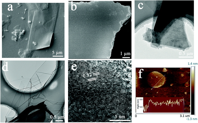
Further, the ordered morphologies of the COF sheets were characterized by SEM, TEM and AFM. As shown in Fig. 3a, b and Fig. S6 (ESI†), what's exciting is that the COF sheets grown via this strategy exhibit almost perfect morphologies with a super-large size (>200 μm2), smooth surface and regular shape, which have not been observed to date, and also a clear layered stacking structure. Fig. 3c and d show TEM images of the NS-COF after ultrasonic pretreatment. From Fig. 3c, we can recognize that the thickly stacked layer structures of the COF nanosheets are formed by layer-by-layer deposition of thinner ones. Moreover, the clear lamellar structure of the COF nanosheet can also be observed in Fig. 3b and Fig. S6 and S7 (ESI†). Fig. 3d shows a single-layer or few-layer NS-COF sheet obtained through full exfoliation by ultrasonic treatment. The NS-COF thin film looks somewhat like a graphene sheet. The layer spacing of the NS-COF is found to be ∼0.32 nm from the HR-TEM image shown in Fig. 3e, which is fitted with a π–π stacking distance of ∼0.33 nm given by Materials Studio (MS) simulation. Moreover, we employ atomic force microscopy (AFM) to characterize the thickness of the NS-COF layer. The NS-COF nanosheets were dispersed sufficiently with ultrasound before AFM measurements. As shown in Fig. 3f, the thickness of the nanosheet is about 0.35 nm, which is consistent with the layer spacing obtained from HR-TEM and the result calculated by MS software.
TGA and DSC curves of the NS-COF are shown in Fig. S8 (ESI†). It can be seen that the pyrolysis process uncovers three main stages. The first stage (∼5% weight loss), evolving from 50 °C to 150 °C, could be attributed to the loss of adsorbed water or residual solvents;48 the second stage with a weight loss of about 25% is mainly due to the loss of phenolic hydroxyl groups; the skeleton structure of the NS-COF begins to degrade slowly and continuously as the temperature increases up to around 400 °C and higher. The results indicate that the NS-COF is stable within 300 °C.
In addition, the solvent stability of the NS-COF is evaluated by immersing the solid products in 5 kinds of solvents, respectively, for 24 h, and the results are shown in Fig. S9 (ESI†). It can be seen that the NS-COF retained their original structural integrity in all solvents selected.
On the other hand, uranium is an important energy-related resource with radiological, chemical and biological toxicity, so detection and recovery of uranium from various uranium-containing aqueous solutions are of great significance.49–53 As predesigned in advance, the existence of huge amounts of carbonyl groups and salicylideneimine-like structures, which were reported to have excellent affinity and selectivity towards uranium, would make the NS-COF a potential candidate for the efficient separation and recovery of uranium.52 In addition, the NS-COF can also emit visible fluorescence when induced by UV light, and the characteristic of photoluminescence (PL) might promise NS-COF a feasible application for UO22+ sensing. Therefore, we investigated the fluorescence response and adsorption behavior of the NS-COF to uranyl ions, and the results are shown in Fig. 4.
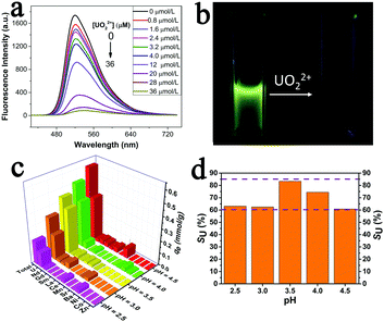
As displayed in Fig. 4a, the fluorescence intensities of NS-COF dispersions decreased gradually upon adding UO22+. The experimental results show that the NS-COF has a much higher fluorescence response to UO22+ even at a uranyl concentration as low as 0.2 ppm. When the concentration of UO22+ increased to 36 μM (8.6 ppm), the fluorescence could be quenched almost completely (Fig. 4a and b).
Furthermore, we investigated the sorption behavior of the NS-COF to uranyl ions in a simulated nuclear industry effluent sample containing 12 coexistent nuclides. As shown in Fig. 4c and d, the sorbing capacity (qe, see the ESI,† Section S11) of the NS-COF for all the metal ions almost linearly increased with an increase in pH from 2.5 to 4.5. The NS-COF exhibits a much higher uranium selectivity (SU, see the ESI,† Section S11) of >60% with a maximum sorbing capacity of 91 mg g−1 over the whole pH range tested. In particular, the SU can reach as high as 83% at pH around 3.5. The results indicated that the uranium selectivity for the NS-COF is superior to most of the reported sorbents under similar conditions.53 To understand the mechanisms of the highly sensitive detection and highly selective sorption of UO22+ by the NS-COF, we employed XPS to explore the interaction between the NS-COF and uranyl ions.
The O1s and N1s signals of the NS-COF before and after uranium loading are shown in Fig. S10 (ESI†) respectively. As we can see, the binding energies of C![[double bond, length as m-dash]](https://www.rsc.org/images/entities/char_e001.gif) O (531.32 eV) and C–OH (533.18 eV) in Fig. S10a (ESI†) shift to higher values (C
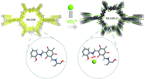
O (531.32 eV) and C–OH (533.18 eV) in Fig. S10a (ESI†) shift to higher values (C![[double bond, length as m-dash]](https://www.rsc.org/images/entities/char_e001.gif) O 531.53 eV and C–OH 533.28 eV; in Fig. S10b (ESI†)) after sorption. The positive shift testifies to the existence of chemical bonding between uranyl and the oxygen donor atoms in the NS-COF.51,53 However, the binding energies of the N1s signal (Fig. S10c and d, ESI†) remains nearly the same before and after uranium loading, from which we could speculate that the nitrogen atoms are not involved in the cooperative bonding to UO22+ during the sensitive detection and selective sorption processes. This is because when the uranyl ion gets close to the nitrogen atom, it would be repelled by the hydrogen atom linked to the nitrogen, while the coordination with the adjacent two oxygen atoms would not be affected by the repulsive interactions. The results could also verify the designed structure of the as-synthesized NS-COF as indirect evidence. A possible detection and separation mechanism between NS-COF nanosheets and UO22+ is proposed and shown in Scheme 2.
O 531.53 eV and C–OH 533.28 eV; in Fig. S10b (ESI†)) after sorption. The positive shift testifies to the existence of chemical bonding between uranyl and the oxygen donor atoms in the NS-COF.51,53 However, the binding energies of the N1s signal (Fig. S10c and d, ESI†) remains nearly the same before and after uranium loading, from which we could speculate that the nitrogen atoms are not involved in the cooperative bonding to UO22+ during the sensitive detection and selective sorption processes. This is because when the uranyl ion gets close to the nitrogen atom, it would be repelled by the hydrogen atom linked to the nitrogen, while the coordination with the adjacent two oxygen atoms would not be affected by the repulsive interactions. The results could also verify the designed structure of the as-synthesized NS-COF as indirect evidence. A possible detection and separation mechanism between NS-COF nanosheets and UO22+ is proposed and shown in Scheme 2.
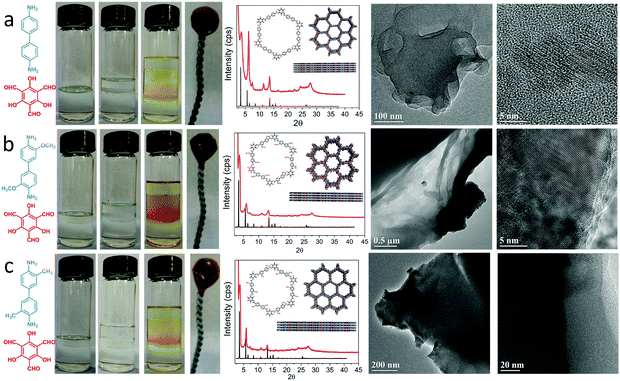
Besides, the applicability of the proposed method was also verified by some other different amine monomers and different combinations of solvents; the preparation and characterization of the products can be seen in Fig. 5 and 6. It is noteworthy that the solubility of DHBD is poor in common organic solvents due to the strong hydrogen bonds between molecules. So the methylene chloride–DMF mixed solvent was chosen in the above experiments. In order to show the impact of changes in solvent combinations more intuitively, an amine monomer with a similar structure but better solubility was newly chosen as a substituent. The structure of the COF nanosheets prepared from other solvent combination systems is shown in Fig. S13 (ESI†). This method does not need to consider whether the selected solvent is a single organic solvent or a mixed organic solvent, as long as it can dissolve the selected monomers. The results of the additional experiments validate that our strategy is feasible and practicable within a certain range. For more detailed information about the applicability of the proposed method, please see the ESI,† Section S13.
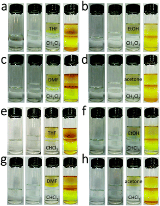 | ||
| Fig. 6 Digital images of different preparation processes with different solvent combinations (TFP dissolved in CH2Cl2 and CHCl3; DMBD dissolved in different common organic solvents). | ||
Conclusions
In conclusion, based on the self-propelled directed motion of the interface induced by density differences, a novel buffering interlayer interface (BII) approach, also called a sandwich-type organic solvent system (solvent A–buffer C–solvent B), is designed and employed, for the first time, to achieve the expected goal of building high quality 2D COF nanosheets at the interface of two miscible organic solvents. The NS-COF nanosheets possess a fine morphology: micron-size sheets, a smooth surface, a relatively regular polygonal shape and a 2D layered structure with an unusual ABC stacking mode. Moreover, the NS-COF exhibits high thermal stability and good organic solvent stability and shows great potential applications in highly sensitive detection and selective sorption of UO22+.For the practical application of the proposed sandwich-type organic–organic interface reaction model, only the density differences among the organic solvents selected and the solubility of the handpicked monomers need to be considered, regardless of whether the two main solvents (A and B) are immiscible or not, which provides a facile approach for design and construction of highly-quality 2D COF nanosheets. In addition, compared with most of the other approaches reported to date, the synthesis process involved in this strategy has the following characteristics: (1) a simple procedure; (2) an easy and safe operation; and (3) mild reactive conditions without additional requirements for high vacuum or high temperature sealed-tube reactions or even various stripping approaches unless specifically required. These give our strategy more extensive adaptability and substantial practical value superior to the other approaches reported so far.
Conflicts of interest
There are no conflicts to declare.Acknowledgements
The financial support from the Science Challenge Project TZ2016004, the National Natural Science Foundation of China (Grants 21671140 and 21771128) and the Fundamental Research Funds for the Central Universities is gratefully acknowledged.References
- Z. Chang, D. S. Zhang, Q. Chen and X. H. Bu, Phys. Chem. Chem. Phys., 2013, 15, 5430–5442 RSC.
- W. C. Song, X. K. Xu, Q. Chen, Z. Z. Zhuang and X. H. Bu, Polym. Chem., 2013, 4, 4690–4696 RSC.
- D. S. Zhang, Z. Chang, Y. B. Lv, T. L. Hu and X. H. Bu, RSC Adv., 2012, 2, 408–410 RSC.
- Y. Zeng, R. Zou and Y. Zhao, Adv. Mater., 2016, 28, 2855–2873 CrossRef CAS PubMed.
- R. W. Tilford, S. J. Mugavero III, P. J. Pellechia and J. J. Lavigne, Adv. Mater., 2008, 20, 2741–2746 CrossRef CAS PubMed.
- S. Y. Ding, M. Dong, Y. W. Wang, Y. T. Chen, H. Z. Wang, C. Y. Su and W. Wang, J. Am. Chem. Soc., 2016, 138, 3031–3037 CrossRef CAS PubMed.
- N. Huang, L. Zhai, H. Xu and D. Jiang, J. Am. Chem. Soc., 2017, 139, 2428–2434 CrossRef CAS PubMed.
- Q. Sun, B. Aguila, J. Perman, L. D. Earl, C. W. Abney, Y. Cheng, H. Wei, N. Nguyen, L. Wojtas and S. Ma, J. Am. Chem. Soc., 2017, 139, 2786–2793 CrossRef CAS PubMed.
- S. B. Alahakoon, C. M. Thompson, G. Occhialini and R. A. Smaldone, ChemSusChem, 2017, 10, 2116–2129 CrossRef CAS PubMed.
- C. R. DeBlase, K. E. Silberstein, T. T. Truong, H. D. Abruna and W. R. Dichtel, J. Am. Chem. Soc., 2013, 135, 16821–16824 CrossRef CAS PubMed.
- X. Zhan, Z. Chen and Q. Zhang, J. Mater. Chem. A, 2017, 5, 14463–14479 CAS.
- S. Chandra, D. Roy Chowdhury, M. Addicoat, T. Heine, A. Paul and R. Banerjee, Chem. Mater., 2017, 29, 2074–2080 CrossRef CAS.
- Q. Sun, B. Aguila, J. Perman, N. Nguyen and S. Ma, J. Am. Chem. Soc., 2016, 138, 15790–15796 CrossRef CAS PubMed.
- Q. Lin, X. Bu, A. Kong, C. Mao, F. Bu and P. Feng, Adv. Mater., 2015, 27, 3431–3436 CrossRef CAS PubMed.
- C. Y. Lin, L. Zhang, Z. Zhao and Z. Xia, Adv. Mater., 2017, 29, 1606635 CrossRef PubMed.
- R. Xue, H. Guo, T. Wang, L. Gong, Y. Wang, J. Ai, D. Huang, H. Chen and W. Yang, Anal. Methods, 2017, 9, 3737–3750 RSC.
- M. R. Rao, Y. Fang, S. De Feyter and D. F. Perepichka, J. Am. Chem. Soc., 2017, 139, 2421–2427 CrossRef CAS PubMed.
- Y. Peng, Y. Huang, Y. Zhu, B. Chen, L. Wang, Z. Lai, Z. Zhang, M. Zhao, C. Tan, N. Yang, F. Shao, Y. Han and H. Zhang, J. Am. Chem. Soc., 2017, 139, 8698–8704 CrossRef CAS PubMed.
- J. L. Segura, M. J. Mancheno and F. Zamora, Chem. Soc. Rev., 2016, 45, 5635–5671 RSC.
- R. P. Bisbey and W. R. Dichtel, ACS Cent. Sci., 2017, 3, 533–543 CrossRef CAS PubMed.
- C. R. DeBlase and W. R. Dichtel, Macromolecules, 2016, 49, 5297–5305 CrossRef CAS.
- G. Li, K. Zhang and T. Tsuru, ACS Appl. Mater. Interfaces, 2017, 9, 8433–8436 CAS.
- I. Berlanga, M. L. Ruiz-Gonzalez, J. M. Gonzalez-Calbet, J. L. Fierro, R. Mas-Balleste and F. Zamora, Small, 2011, 7, 1207–1211 CrossRef CAS PubMed.
- I. Berlanga, R. Mas-Balleste and F. Zamora, Chem. Commun., 2012, 48, 7976–7978 RSC.
- D. N. Bunck and W. R. Dichtel, J. Am. Chem. Soc., 2013, 135, 14952–14955 CrossRef CAS PubMed.
- Y. Yang, F. Bu, J. Liu, I. Shakir and Y. Xu, Chem. Commun., 2017, 53, 7481–7484 RSC.
- S. Chandra, S. Kandambeth, B. P. Biswal, B. Lukose, S. M. Kunjir, M. Chaudhary, R. Babarao, T. Heine and R. Banerjee, J. Am. Chem. Soc., 2013, 135, 17853–17861 CrossRef CAS PubMed.
- B. P. Biswal, S. Chandra, S. Kandambeth, B. Lukose, T. Heine and R. Banerjee, J. Am. Chem. Soc., 2013, 135, 5328–5331 CrossRef CAS PubMed.
- D. B. Shinde, H. B. Aiyappa, M. Bhadra, B. P. Biswal, P. Wadge, S. Kandambeth, B. Garai, T. Kundu, S. Kurungot and R. Banerjee, J. Mater. Chem. A, 2016, 4, 2682–2690 CAS.
- S. Wang, Q. Wang, P. Shao, Y. Han, X. Gao, L. Ma, S. Yuan, X. Ma, J. Zhou, X. Feng and B. Wang, J. Am. Chem. Soc., 2017, 139, 4258–4261 CrossRef CAS PubMed.
- M. A. Khayum, S. Kandambeth, S. Mitra, S. B. Nair, A. Das, S. S. Nagane, R. Mukherjee and R. Banerjee, Angew. Chem., Int. Ed., 2016, 55, 15604–15608 CrossRef CAS PubMed.
- S. Mitra, H. S. Sasmal, T. Kundu, S. Kandambeth, K. Illath, D. Diaz Diaz and R. Banerjee, J. Am. Chem. Soc., 2017, 139, 4513–4520 CrossRef CAS PubMed.
- T.-Y. Zhou, F. Lin, Z.-T. Li and X. Zhao, Macromolecules, 2013, 46, 7745–7752 CrossRef CAS.
- A. B. Marco, D. Cortizo-Lacalle, I. Perez-Miqueo, G. Valenti, A. Boni, J. Plas, K. Strutynski, S. De Feyter, F. Paolucci, M. Montes, A. N. Khlobystov, M. Melle-Franco and A. Mateo-Alonso, Angew. Chem., Int. Ed., 2017, 56, 6946–6951 CrossRef CAS PubMed.
- S. Mitra, S. Kandambeth, B. P. Biswal, M. A. Khayum, C. K. Choudhury, M. Mehta, G. Kaur, S. Banerjee, A. Prabhune, S. Verma, S. Roy, U. K. Kharul and R. Banerjee, J. Am. Chem. Soc., 2016, 138, 2823–2828 CrossRef CAS PubMed.
- Q. Fan, J. M. Gottfried and J. Zhu, Acc. Chem. Res., 2015, 48, 2484–2494 CrossRef CAS PubMed.
- L. Xu, X. Zhou, W. Q. Tian, T. Gao, Y. F. Zhang, S. Lei and Z. F. Liu, Angew. Chem., Int. Ed., 2014, 53, 9564–9568 CrossRef CAS PubMed.
- X. H. Liu, C. Z. Guan, D. Wang and L. J. Wan, Adv. Mater., 2014, 26, 6912–6920 CrossRef CAS PubMed.
- D. J. Murray, D. D. Patterson, P. Payamyar, R. Bhola, W. Song, M. Lackinger, A. D. Schluter and B. T. King, J. Am. Chem. Soc., 2015, 137, 3450–3453 CrossRef CAS PubMed.
- P. Payamyar, K. Kaja, C. Ruiz-Vargas, A. Stemmer, D. J. Murray, C. J. Johnson, B. T. King, F. Schiffmann, J. Vandevondele, A. Renn, S. Gotzinger, P. Ceroni, A. Schutz, L. T. Lee, Z. Zheng, J. Sakamoto and A. D. Schluter, Adv. Mater., 2014, 26, 2052–2058 CrossRef CAS PubMed.
- W. Dai, F. Shao, J. Szczerbinski, R. McCaffrey, R. Zenobi, Y. Jin, A. D. Schluter and W. Zhang, Angew. Chem., Int. Ed., 2016, 55, 213–217 CrossRef CAS PubMed.
- H. Sahabudeen, H. Qi, B. A. Glatz, D. Tranca, R. Dong, Y. Hou, T. Zhang, C. Kuttner, T. Lehnert, G. Seifert, U. Kaiser, A. Fery, Z. Zheng and X. Feng, Nat. Commun., 2016, 7, 13461–13468 CrossRef PubMed.
- K. Dey, M. Pal, K. C. Rout, H. S. Kunjattu, A. Das, R. Mukherjee, U. K. Kharul and R. Banerjee, J. Am. Chem. Soc., 2017, 139, 13083–13091 CrossRef CAS PubMed.
- A. C. Ferrari and J. Robertson, Phys. Rev. B: Condens. Matter Mater. Phys., 2000, 61, 14095–14107 CrossRef CAS.
- T. I. T. Okpalugo, P. Papakonstantinou, H. Murphy, J. McLaughlin and N. M. D. Brown, Carbon, 2005, 43, 153–161 CrossRef CAS.
- A. P. Dementjev, A. de Graaf, M. C. M. van de Sanden, K. I. Maslakov, A. V. Naumkin and A. A. Serov, Diamond Relat. Mater., 2000, 9, 1904–1907 CrossRef CAS.
- G. Ketteler, S. Yamamoto, H. Bluhm, K. Andersson, D. E. Starr, D. F. Ogletree, H. Ogasawara, A. Nilsson and M. Salmeron, J. Phys. Chem. C, 2007, 111, 8278–8282 CAS.
- M. Worzakowska, J. Therm. Anal. Calorim., 2017, 129, 367–376 CrossRef CAS.
- M. L. Feng, D. Sarma, X. H. Qi, K. Z. Du, X. Y. Huang and M. G. Kanatzidis, J. Am. Chem. Soc., 2016, 138, 12578–12585 CrossRef CAS PubMed.
- Y. Wang, Z. Liu, Y. Li, Z. Bai, W. Liu, Y. Wang, X. Xu, C. Xiao, D. Sheng, J. Diwu, J. Su, Z. Chai, T. E. Albrecht-Schmitt and S. Wang, J. Am. Chem. Soc., 2015, 137, 6144–6147 CrossRef CAS PubMed.
- Y. Tian, J. Fu, Y. Zhang, K. Cao, C. Bai, D. Wang, S. Li, Y. Xue, L. Ma and C. Zheng, Phys. Chem. Chem. Phys., 2015, 17, 7214–7223 RSC.
- H. Wang, L. Ma, K. Cao, J. Geng, J. Liu, Q. Song, X. Yang and S. Li, J. Hazard. Mater., 2012, 229, 321–330 CrossRef PubMed.
- Y. Li, L. Wang, B. Li, M. Zhang, R. Wen, X. Guo, X. Li, J. Zhang, S. Li and L. Ma, ACS Appl. Mater. Interfaces, 2016, 8, 28853–28861 CAS.
Footnote |
| † Electronic supplementary information (ESI) available. See DOI: 10.1039/c7nh00172j |
| This journal is © The Royal Society of Chemistry 2018 |

