
Surface confined titania redox couple for ultrafast energy storage†
Jian
Zhi‡
 a,
Houlei
Cui‡
a,
Zhou
Wang
a and
Fuqiang
Huang
*ab
a,
Houlei
Cui‡
a,
Zhou
Wang
a and
Fuqiang
Huang
*ab
aState Key Laboratory of High Performance Ceramics and Superfine Microstructure, Shanghai Institute of Ceramics, Chinese Academy of Sciences, Shanghai 200050, P. R. China. E-mail: huangfq@mail.sic.ac.cn
bBeijing National Laboratory for Molecular Sciences and State Key Laboratory of Rare Earth Materials Chemistry and Applications, College of Chemistry and Molecular Engineering, Peking University, Beijing 100871, P. R. China
First published on 3rd May 2018
Abstract
Practical large-scale energy storage should deliver high capacitance/capacity with an ultrahigh rate and do so economically over multiple cycles. Existing electrode materials, however, have fallen short of these requirements in one measure or another. Here, we have discovered a surface confined titania redox couple on black TiO2 nanotube arrays (B-TNAs). Such rapid Ti3+/Ti4+ conversion provides an outstanding rate for B-TNAs of 400 mA cm−2 in supercapacitors (SCs) and 200 C in lithium ion batteries (LiBs), with negligible capacitance/capacity fading for up to 15![[thin space (1/6-em)]](https://www.rsc.org/images/entities/char_2009.gif) 000 cycles. The ultrafast pseudocapacitive behaviour from black titania suggests a new family of electrode materials, which may offer a way to overcome the present difficulties of SCs and LiBs in grid-scale energy storage systems.
000 cycles. The ultrafast pseudocapacitive behaviour from black titania suggests a new family of electrode materials, which may offer a way to overcome the present difficulties of SCs and LiBs in grid-scale energy storage systems.
Conceptual insightsThis study reports a unique electrochemical phenomenon in one dimensional black TiO2 nanotube arrays, the “Ti3+/Ti4+ redox couple”, and proposes a new type of electrode material. The introduction of surface Ti3+ sites can increase local carrier density by three orders of magnitude, and significantly improve the surface conductivity of TiO2. Compared with other metal oxides that mainly perform redox reactions in the bulk, such “conductive surface” confined redox systems enable much faster ion diffusion kinetics and provide an unprecedented rate capability for black TiO2 in both supercapacitors and lithium ion batteries. Considering that Ti is naturally abundant and is the lightest transition metal element with multiple oxidation states, this discovery does suggest a special place for TiO2 as an active electrode material in high-rate energy storage. |
Energy storage systems (ESSs) play an important role in auxiliary power services, system balancing of variable resources and grid optimization.1,2 Without an ESS, the grid system must depend on redundant generation to meet reliability requirements, resulting in the underuse of infrastructure.3,4 The requirements of a grid-scale ESS include long cycle life, fast response time and high round-trip efficiency. Of all types of energy storage system, supercapacitors (SCs) and Li ion batteries (LiBs) stand out as meeting all the requirements.5,6 Their high power densities have positioned SCs as front runners in large-scale ESSs. The flexibility of LiBs in system design for either energy application (e.g., long-term load shifting) or power (e.g., short-term frequency regulation) is an asset for renewable integration.
Despite technological advances achieved in recent years, neither SCs nor LiBs are commercially ready for market entry due to certain challenges. In grid application, an ultrahigh rate of over 100 mA cm−2 or 100 C is required to optimize ancillary services.7 Unfortunately, most metal-oxide based active materials in SCs and LiBs show poor electrochemical performance under such a rate owing to slow ion diffusion kinetics.8 Carbonaceous materials, such as carbon nanoparticles and graphene, have relatively better rate capabilities, but their energy densities are quite low.9 Therefore, further exploration of new electrode materials with superior rate capabilities is highly urgent to make SCs and LiBs feasible in large scale energy storage.
TiO2 has been widely studied as a photocatalyst and an anode electrode in dye-sensitized solar cells. Its appeal is further enhanced by the recent development of hydrogenated TiO2 with oxygen vacancies, which was utilized in SCs and LiBs as an electrode. However, as an anode material, hydrogenated TiO2 only exhibited modest cycling stabilities (ranging from 100–500 cycles) under rates lower than 100 C.10,11 Corresponding studies of TiO2 in a supercapacitor giving an areal capacitance up to 87 mF cm−2 were not encouraging either.12,13 This is surprising: being an n-type semiconductor with a redox potential (Ti3+/Ti4+) just +0.1 V relative to H/H+, TiO2 should easily participate in redox mechanisms, and result in superior electrochemical performance.
Inspired by this speculation, here we have discovered a surface confined titania redox couple on black TiO2 nanotube arrays (B-TNAs). Such rapid Ti3+/Ti4+ conversion provides an outstanding rate for B-TNAs of 400 mA cm−2, which is at least 1 order of magnitude faster than the speeds of current supercapacitor devices. After skinning a pseudocapacitive polymer (polyaniline, PANI), the capacitance of B-TNA/PANI in asymmetrical supercapacitors can be boosted up to 181 mF cm−2 at 400 mA cm−2, with 92% capacitance retention after 15000 cycles. More importantly, we also found a similar titania redox process from a B-TNA electrode in a LiBs system. A high rate up to 200 C (equivalent to a full discharge in 18 s) was obtained in a B-TNA/PANI//Li half-cell, with 83% capacity retention after 2000 cycles. This discovery enables a new family of electrode materials for SCs and LiBs with unprecedented rate capabilities in addition to exceptional cycling stabilities, which perfectly match the requirements of grid scale energy storage. Extensive microscopy, and ex situ and in situ spectroscopy characterization was employed to provide an understanding of the key functions of this unique surface redox process, and the corresponding mechanism has been proposed.
B-TNAs with the anatase structure (JCPDF No. 21-1272, Fig. S1, ESI†) were synthesized via a two-step electrochemical anodization process, followed by our simple and easy-to-scale aluminium (Al)-reduction technique. FE-SEM (field-emission scanning electron microscopy) was applied to investigate the morphology of the B-TNAs. Fig. 1a exhibits the FE-SEM images of the B-TNAs from different directions. It is clear that the vertically aligned nanotubes have a thickness of 20 nm and a diameter of 100 nm, which is identical to typical TNAs.14 The side-view image (inset of Fig. 1a) indicates that the walls of the B-TNAs are highly porous with many tunnels along the nanotube walls. Raman spectra of the TNA samples were measured to investigate the surface chemical compositions and corresponding oxidation states. As shown in Fig. S2 (ESI†), all the plots show four characteristic peaks of anatase TiO2, located at ∼141 cm−1, ∼393 cm−1, ∼513 cm−1, and ∼636 cm−1. Compared with the spectra of the TNAs, the noteworthy blue shift and peak broadening of the band at 141 cm−1 for the B-TNAs indicates the increased amount of oxygen vacancies.15 Fig. S3 (ESI†) further shows the Ti 2p XPS spectra of B-TNA/PANI. Ti4+–O bonds are obviously verified by the two peaks centred at binding energies of about 458.3 eV and 464.0 eV, which correspond to the characteristic peaks of Ti 2p3/2 and Ti 2p1/2, respectively, in the Ti4+–O bonding structure.16 Moreover, two peaks centred separately at 456.9 and 464.2 eV in B-TNAs correspond to the 2p3/2 and 2p1/2 peaks of Ti3+, respectively, which is attributed to the considerable intake of Ti3+ states on the surface of the TNA layer via the reduction process.17 To study the impact of Al-reduction on the electrical properties of TiO2, electrochemical impedance measurements were performed on TNAs and B-TNAs. Mott–Schottky plots were obtained according to the capacitances at different potentials under 10 kHz frequency in the dark. It is clear that TNA and B-TNA samples both show a positive slope in Fig. 1b, indicating typical n-type semiconductor behavior. Surface carrier densities of TiO2 samples can be calculated using the Mott–Schottky equation (1)
 | (1) |
 stand for the electron charge, the dielectric constant of TiO2 (31 for anatase), the permittivity of a vacuum, the donor density and the straight slope, respectively. According to this equation, the calculated surface electron densities of the B-TNAs and TNAs are 3.76 × 10²¹ and 5.38 × 1018 cm−3, respectively. Due to the introduction of a substantial amount of Ti3+ (oxygen vacancies) serving as donors, Al-reduction induces an exponential increase in electron density, which is beneficial for improving the electrical conductivity of the sample. Compared to pristine TNAs, B-TNAs show more intense UV-visible light-IR absorption (Fig. S4, ESI†) owing to the abundant surface Ti3+ sites (oxygen vacancies). As a result, the B-TNA sample is completely black in colour (Fig. 1c), similar to other Al-reduced materials synthesized in our group.18 TNA and B-TNA samples were further characterised using electron paramagnetic resonance (EPR) spectroscopy to investigate paramagnetic species containing unpaired electrons. B-TNAs give rise to a strong EPR signal, whereas no signal was seen for TNAs (Fig. 1d). The three g tensor values for black B-TNAs (g1 = 2.00, g2 = 2.001, g3 = 1.99)17 are consistent with the value of a single-electron-trapped oxygen vacancy.18 Such a distinct signal could be assigned to the large amount of Ti3+ containing unpaired electrons existing on the surface of the B-TNTs. To perform a careful analysis of Ti3+ on the depth scale, B-TNA powder scratched from Ti foil was subjected to successive etching using 700 eV Ar+ ions, which has been widely used to verify the surface enrichment of specific elements.19–21 Fig. S5 (ESI†) shows the Ti 2p XPS spectra with different etching times. The Ti3+ contribution observed in the spectrum of the B-TNA sample (Fig. S5a, ESI†) increases considerably after etching for 5 min (Fig. S5b, ESI†). After a further 5 min of etching (Fig. S5c, ESI†), there is a decrease in the Ti3+ signal relative to the Ti4+ signal. The Ti3+ signal became very faint when the sample was subjected to a 20 min final etching (Fig. S5e, ESI†). Note that the etching rate was about 0.5 nm min−1 and quantitative information on the [Ti3+]/[Ti4+] area ratio from the XPS spectra as a function of depth can be obtained (Fig. S5f, ESI†). From this figure, it can be observed that Ti3+ concentration is highest at the surface of the sample, and the “depth” of Ti3+ was estimated to be 10 nm.
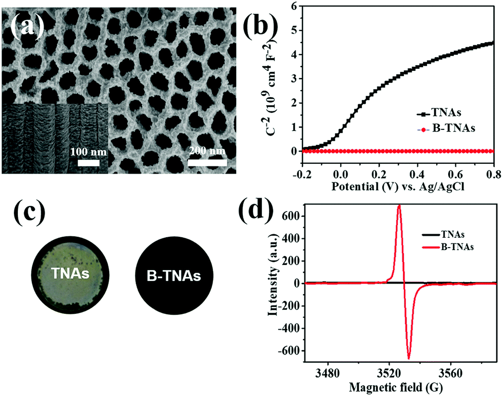 | ||
| Fig. 1 (a) FE-SEM images of B-TNAs (top and side view). (b) Mott–Schottky plots of TNAs and B-TNAs at 10 kHz in the dark. (c) Photographs of TNAs and B-TNAs grown on Ti foil. (d) Electron paramagnetic resonance (EPR) spectroscopy of TNAs and B-TNAs. | ||
The electrochemical properties of the B-TNAs were measured in a three-electrode cell with a Pt counter electrode and an Ag/AgCl reference electrode. In 1 M H2SO4 aqueous solution, the dramatic improvement of the B-TNAs over pristine TNAs is evident from CV at 100 mV s−1 (Fig. 2a). Compared with other metal oxide materials with similar rectangular shapes (MnO2, RuO2), the most important characteristic of B-TNAs is the high sweep rate endurance from 0.1 to 1 V s−1 (Fig. 2b), ranking among the highest scan rates reported.22 We further examined the charge–discharge ability of B-TNAs at high current densities from 1 to 400 mA cm−2 (Fig. 2c). B-TNAs show ultrafast and reversible charge and discharge even at 400 mA cm−2 (Fig. S6, ESI†). Corresponding areal capacitances are up to 168 and 63 mF cm−2 at 1 and 400 mA cm−2, respectively. To avoid hydrogen evolution (at <0 VRHE = reversible hydrogen electrode voltage) and oxygen evolution (at >1.23 VRHE), we selected the following voltage window: 0.2–1 VRHE at pH = 0 (as well as in 1 M H2SO4 aqueous electrolyte solution), corresponding to 0–0.8 VAg/AgCl. The obtained areal capacitances compared favorably with values recently reported for TNAs (0.538 mF cm−2)23 and other modified TNA materials (up to 3.24 mF cm−2)24,25 and is even higher than the capacitance obtained from Ni–NiO pseudocapacitive materials.26 Note that all these capacitances were measured at relatively slow rates (not exceeding 100 mA cm−2) and that the high capacitance of B-TNAs at 400 mA cm−2 undoubtedly shows a unique ultrafast charge–discharge ability. Dynamic characteristics in electrochemical impedance spectroscopy (EIS) likewise suggest fast ion transport kinetics in B-TNA electrodes. Unlike TNA electrodes that have extremely low electrical conductivity (Fig. S7, ESI†), B-TNA electrodes display a purely capacitive behaviour in the Cole–Cole plot (Fig. 2d) with a small complex impedance at frequencies below ∼10 Hz. After fitting (see Fig. S8, ESI† for the corresponding equivalent circuit), the Cole–Cole plot has a real-part impedance of 1.5 ohm at the high-frequency limit, which matches the earlier estimate of the ESR (1.7 ohm) from the initial voltage drop in the charge–discharge curve.
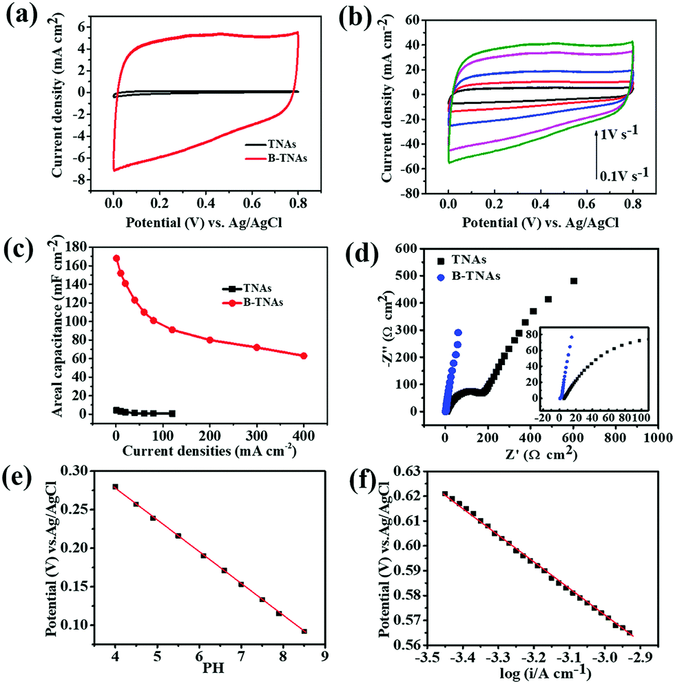 | ||
| Fig. 2 (a) CV curves of TNAs and B-TNAs at 100 mV s−1. (b) CV of B-TNAs from 0.1 to 1 V s−1. (c) Specific capacitance of B-TNAs and TNAs as a function of current density (1–400 mA cm−2). (d) Nyquist plots of TNAs and B-TNAs. (e) pH dependence of steady-state B-TNA potential at 0.5 μA cm−2 in 1 M KH2PO4 solution. (f) Electrode potential as a function of current density in the Tafel zone characterized in 1 M H2SO4. | ||
The very low ESR from the EIS measurement very likely suggests that the output voltage is rather close to the actual electrochemical potential of the electrode reactions. Assuming so, we investigated the electrochemical mechanism of charge storage. Analysing B-TNA electrode potential in KH2PO4 electrolytes and H2SO4 at room temperature, we found a strong sensitivity to pH (Fig. 2e) and the steady-state current (Fig. 2f). Therefore, we propose the following redox reactions, allowing reversible protonation/deprotonation of the B-TNA electrode to account for surface Ti3+/Ti4+ conversion.
| TiO2−x + yH+ + ye− ↔ TiO2−x−y(O–H)y, | (2) |
![[thin space (1/6-em)]](https://www.rsc.org/images/entities/i_char_2009.gif) ln(α(H+)) for an incorporation/chemisorption reaction that involves z electrons, and exp(−ΔG/RT) and the steady-state reaction current I can follow the below equation:
ln(α(H+)) for an incorporation/chemisorption reaction that involves z electrons, and exp(−ΔG/RT) and the steady-state reaction current I can follow the below equation: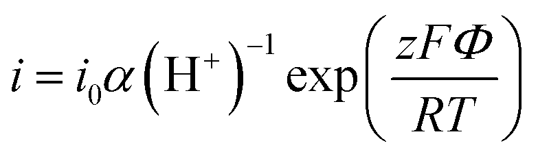 | (3) |
The capacitive character of B-TNAs is strongly related to the carrier density. Table S1 (ESI†) shows the electrochemical properties of B-TNA electrodes prepared via NaBH4 reduction, ambient hydrogen treatment, hydrogen plasma, electrochemical anodizing and Al reduction. Different from other methods that directly dope Ti3+ on the surface, Al reduction produces an extremely high driving force for TiO2 reduction inside the furnace. Under these circumstances, more sub-surface regions of TNAs are involved in reactions, and more Ti3+ sites can be created, resulting in much higher local carrier density than other reduced TNA samples (Table S1, ESI†). B-TNA samples prepared by NaBH4 reduction, ambient hydrogen treatment, hydrogen plasma and electrochemical anodizing were etched using 700 eV Ar+ ions to verify the impact of different reduction methods on the “depth” of the Ti3+ enrichment layer. Fig. S14 (ESI†) shows the corresponding evolution of the [Ti3+/Ti4+] area ratio from the XPS spectra as a function of depth. The concentrations of Ti3+ in these samples all dropped rapidly when the etching depth increases to 5 nm, while Al-reduced samples still retain a high value (Fig. S5f, ESI†). Clearly, more sub-surface regions of TNAs are involved in Al reactions, which results in a relatively thicker surface Ti3+ enrichment layer compared to that of other conventional reduction methods. Such a conductive surface of B-TNAs ensures fast electron transfer along the one-dimensional nanostructures, which greatly accelerates the kinetics of the Ti3+/Ti4+ redox reaction.
Inspired by the surface redox feature of B-TNAs, we prepared polyaniline (PANI) skinned B-TNAs to further improve the high rate performance based on the unique proton-facilitation chemistry of conductive polymers.29 B-TNA/PANI electrodes were synthesized via the electrochemical polymerization of aniline on B-TNAs through 30 repeated cyclic voltammetry scans (experimental section). The side and top view SEM image (inset of Fig. 3a) shows that the tunnels along the wall of TNAs become coarse after the polymerization of PANI. Compared to the B-TNAs, the relatively rougher surface of B-TNA/PANI indicates the existence of PANI on the walls of TNAs, which is confirmed by the transmission electron microscopy (TEM) images (Fig. 3b and c). From the high-resolution TEM image (Fig. 3c), an ultrathin amorphous PANI skin of about 3.2 nm in thickness was identified. Such an ultrathin conductive coating significantly improves the electrical conductivity of B-TNAs. EDS (energy-dispersive X-ray spectroscopy) mapping analysis (Fig. S15, ESI†), Raman spectroscopy (Fig. S16, ESI†) and XPS (Fig. S17, ESI†) all clearly characterize the structure of the PANI skin on B-TNA.
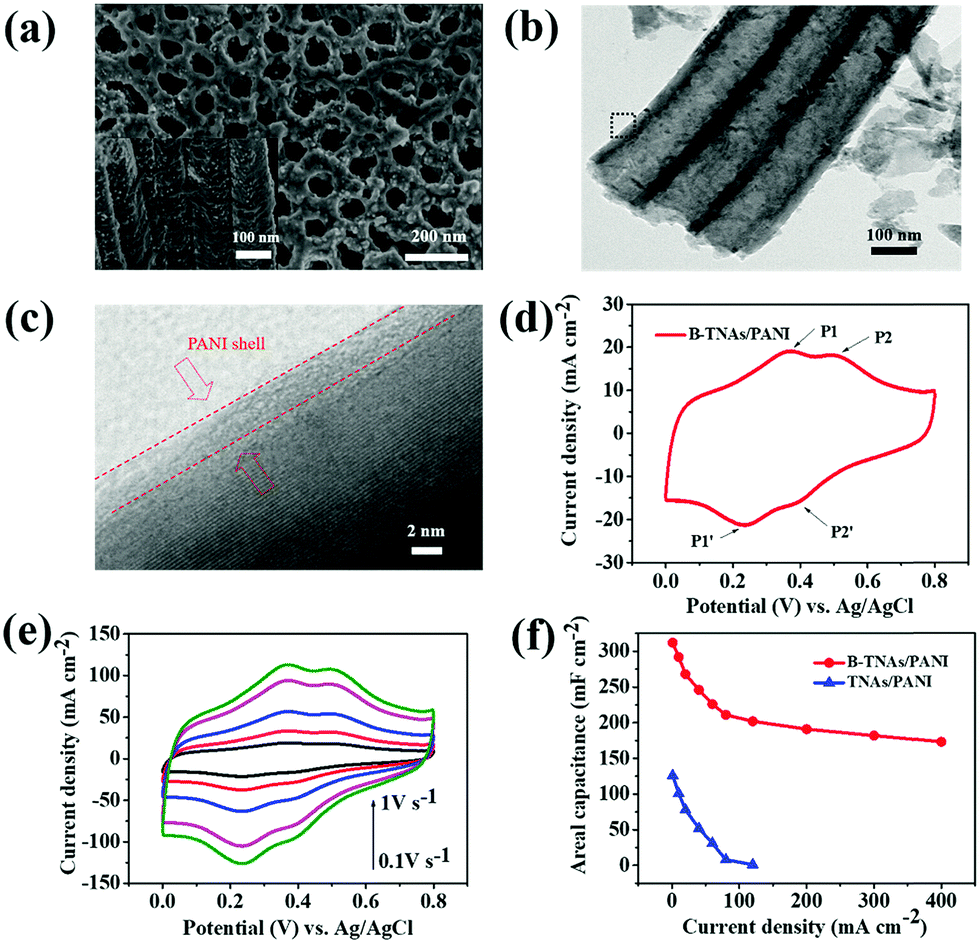 | ||
| Fig. 3 (a) FE-SEM images of B-TNA/PANI (top and side view). (b) TEM image of B-TNA/PANI. (c) High resolution TEM image of the black box shown in Fig. 1b. (d) CV curve of B-TNA/PANI at 100 mV s−1. (e) Sweep rate CV of B-TNA/PANI. (f) Specific capacitance of B-TNA/PANI and TNA/PANI as a function of current density (1–400 mA cm−2). | ||
Fig. 3d shows CV curves of B-TNA/PANI electrodes recorded at 100 mV s−1. Obviously, B-TNA/PANI exhibits two pairs of redox peaks of PANI. The first pair of redox peaks at approximately 0.37/0.24 V (P1/P1′) is related to the transformation from leucoemeraldine to emeraldine states, while the other pair of redox peaks at around 0.51/0.40 V (P2/P2′) stands for the transformation between pernigraniline and emeraldine states.14 It is noteworthy that the amount of PANI coated on B-TNAs significantly affects the total capacitance. Fig. S18 (ESI†) shows CV curves of PANI/B-TNA with different CV scan numbers at 100 mV s−1. Clearly, with increasing scan number, the CV area become larger, indicating the enhancement of the capacitance. However, when the cycle number increases to 60, the area is not increased correspondingly. This is probably due to the agglomeration of PANI on the surface of TNAs, leading to decreased capacitive performance.30
B-TNA/PANI can endure a high sweep rate (Fig. 3e). However, the current density reveals a 4-fold enhancement in comparison to that of B-TNAs (Fig. 1b). The areal capacitances of B-TNA/PANI and TNA/PANI electrodes at different current densities are summarized in Fig. 3f. The maximum areal capacitance of the B-TNA/PANI electrode is 312 mF cm−2 at 1 mA cm−2. This capacitance is much higher than that of the recently reported TNA/PPy electrode (64 mF cm−2)31 and outperforms other supercapacitors using pseudocapacitive materials, such as NiO–TiO2 nanotube arrays (∼2.7 mF cm−2)32 and MnO2 thin films (∼50.2 mF cm−2).33 When the current density increases to 400 mA cm−2, an areal capacitance of up to 173 mF cm−2 still remains with a symmetrical charge/discharge curve (Fig. S19, ESI†), which is 1.7 times higher than the value for B-TNAs (Fig. 2c). Obviously, the conductive polymer skin accelerates the proton transfer of the Ti3+/Ti4+ couple, and further boosts the rate capability. Without the surface redox couple, the areal capacitance of TNA/PANI decreases to nearly zero when the current density reaches 120 mA cm−2 (Fig. 3f). To investigate the cycling stability of the B-TNA/PANI in a three-electrode cell, CV measurement was performed for 2000 cycles at 100 mV s−1. After 2000 cycles, the areal capacitance of B-TNA/PANI can still remain at 89.1% with nearly 100% Coulombic efficiency (Fig. S20, ESI†). The synergistic effect between B-TNAs and PANI ensures rapid proton transfer and robust Ti3+/Ti4+ conversion, leading to superior electrochemical performance. To identify the supercapacitor performance of B-TNAs and B-TNA/PANI in organic electrolyte, symmetric cells of these electrodes using 1 M 1-butyl-3-methylimidazolium tetrafluoro-borate (BMIMBF4)/acetonitrile (AN) as the electrolyte have been assembled. The corresponding charge/discharge curves show that the voltage window of these supercapacitors can be extended up to 2.5 V. However, owing to the extremely low concentration of hydrogen (<10 ppm), both supercapacitors show very limited areal capacitance at a current density of 0.5 mA cm−2 (45 mF cm−2 for B-TNAs and 83 mF cm−2 for B-TNAs/PANI, Fig. S20a, ESI†). This is more direct evidence that the storage capacitance of these electrodes is from the reversible protonation/deprotonation of B-TNAs. Similar observations can be found in symmetric cells employing a 1 M tetraethyl ammonium tetrafluoroborate (TEABF4)/ propylene carbonate (PC) electrolyte, which shows a poor areal capacitance of only 33 mF cm−2 and 68 mF cm−2 for B-TNAs and B-TNA/PANI, respectively (Fig. S20b, ESI†).
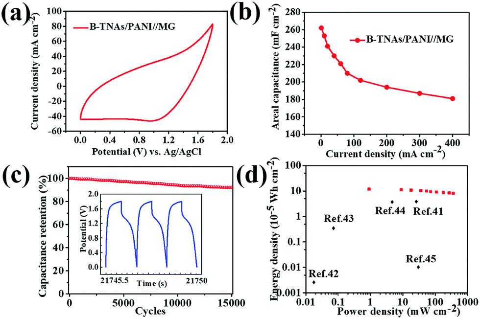
To demonstrate electrochemical energy storage for practical applications, packaged asymmetric SCs in H2SO4 electrolyte were assembled, employing B-TNA/PANI and mesoporous graphene (denoted MG, Fig. S22, ESI†) as positive and negative materials, respectively. Different from the three-electrode cell that is only applied in fundamental research, a two-electrode asymmetrical supercapacitor has a wider range of operating potentials (1.8 V, Fig. 4a for CV curves), which is more applicable in grid-scale energy storage.34 At a current density from 1 to 400 mA cm−2, the B-TNA/PANI//MG asymmetric supercapacitor shows a high areal capacitance of 181 to 262 mF cm−2 (Fig. 4b), which is similar to the results from the three-electrode setup. It may be noted that to achieve charge balance between the positive and negative electrodes, the mass of MG in packaged asymmetric SCs is much higher than that of B-TNA/PANI. The asymmetric supercapacitor shows CV curves with the combination of the positive and negative electrodes. As a result, the much higher mass of MG than of B-TNA/PANI in the device may result in feeble faradaic reactions of PANI and the predominance of an electrical double-layer capacitance derived from MG, which leads to the absence of redox peaks in the CV curves of B-TNA/PANI//MG.35 Similar phenomena have been widely observed in other reports for PANI/carbon asymmetric supercapacitors.35–37 The XRD pattern of the B-TNA/PANI after 10000 cycles in the asymmetric supercapacitor cell is shown in Fig. S23 (ESI†). Compared with XRD patterns of B-TNAs before the cycling test (Fig. S1, ESI†), the anatase structure of TiO2 has been well retained and no new phase emerged in the XRD pattern, which indicates the excellent crystalline stability of B-TNAs during repeated charge/discharge. There are no obvious peaks indexed to PANI, which is characteristic of its amorphous nature caused by the periodicity parallel and perpendicular to the PANI chains.38 Fig. S24a (ESI†) shows the SEM image of the B-TNA/PANI sample after 10000 cycles. The intrinsic 3D TiO2 nanotube arrays are still intact, which confirms the stable structure without obvious deformation and pulverization. As further evidenced by the TEM image (Fig. S24b, ESI†), the in situ formed PANI binding on the surface of TiO2 was also well maintained, suggesting the good preservation of the electrical networks in the electrodes.39 Obviously, the 3D B-TNA/PANI nanoarchitecture has desirable features of mechanically robust architecture and persistent electronic connectivity, which lead to excellent electrochemical performance.
 | ||
| Fig. 4 (a) CV curves of the B-TNA/PANI//MG supercapacitor at 100 mV s−1. (b) Areal capacitances of B-TNAs/PANI//MG supercapacitors at different current densities. (c) Cycle stability of the B-TNA/PANI//MG supercapacitor. The inset in (c) shows the charge/discharge curves of the last three cycles. (d) Ragone plots of the B-TNA/PANI//MG supercapacitor. | ||
In grid applications, supercapacitors often undergo repeated charge–discharge at a large current density.6 As a result, the long-term cycle life of electrode materials is a key requirement for grid operations. For the B-TNA/PANI//MG supercapacitor, 92% of the initial specific capacitance remained after 15000 cycles from 0 to 1.8 V in 1 M H2SO4 aqueous solution at an ultrahigh current density of 400 mA cm−2 as shown in Fig. 4c. The insets in Fig. 4c shows the profiles of the last three cycles. All the curves exhibit the exact same shape, further demonstrating the superior stability. As far as we know, a cycling life exceeding 10000 cycles has rarely been reported for aqueous electrolyte-based asymmetric supercapacitors.40 Energy and power density are two other important properties of energy storage devices in electrical grid applications. The Ragone plots of B-TNA/PANI//MG, originating from galvanostatic charge/discharge curves (ESI† for calculations), are shown in Fig. 4d. Due to the wide potential window (0–1.8 V), both energy and power density are significantly enhanced. At 0.9 mW cm−2, the maximum energy density of the B-TNA/PANI//MG supercapacitor can reach up to 1.79 × 10⁻⁴ W h cm−2, much higher than that of carbon based supercapacitors41–43 and highly comparable with that of metal oxide-based supercapacitors.44,45
Surprisingly, we have also found that B-TNAs have a strong sensitivity to the steady-state current in 1 M LiPF6/ethyl carbonate (EC)/dimethyl carbonate (DMC) electrolyte (Fig. S25, ESI†). After calculating the slopes of the Tafel plots, the data in Fig. S25 (ESI†) shows a ∂Φ/∂log(i) value of 57.33 mV decade−1, which is close to the theoretical value of 59.2 mV decade−1 corresponding to 2.3 × RT/F. Concretely, we determine that z = 1 for B-TNAs, and the titania redox reaction in organic salt electrolyte can follow as:
| TiO2−x + yLi+ + ye− ↔ TiO2−x−y(O–Li)y | (4) |
| i = k1V + k2V1/2 | (5) |
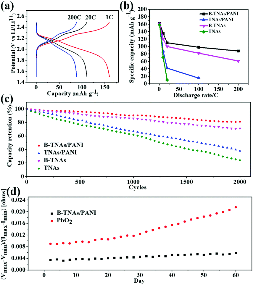 | ||
| Fig. 5 (a) Charge/discharge curves of the B-TNA/PANI//Li half-cell at different rates. (b and c) Rate capabilities from 1 C to 200 C and cyclic performance at 1 C of half-cells employing B-TNA/PANI, TNA/PANI, B-TNAs and TNAs as the anode. (d) Sine wave impedance of a B-TNA/PANI and PbO2 based hybrid battery on different days (all the data were obtained at room temperature). | ||
Fig. 5c compares the cell cycling performance of the B-TNA/PANI anode at 1 C with that of TNA/PANI, B-TNA and TNA anodes. After 2000 cycles, B-TNA/PANI shows the highest capacity retention with about 86% of initial discharge capacity achieved with a coulombic efficiency of nearly 100%. A rapid decay of capacity was observed in the TNA/PANI electrode and the capacity retention showed a continuous decrease to 38%, while TNAs exhibited 24% capacity retention. A PANI coating on TNAs can increase the capacity retention to some extent (47%), however, the value is still not comparable with B-TNA based anodes. It is noteworthy that without PANI skinning, B-TNAs also exhibit a decent capacity retention above 70%, which compares favorably with those of other reported anode materials, including Li4Ti5O12,50,51 Mn3O4,52 Co3O4,53 Fe3O454,55 and SnO2.56 Prompted by the image shown in Fig. S11 (ESI†) for the formation of TiO2−x−y(O–H)y, we propose that the superior cycling life of B-TNA/PANI is mainly derived from the surface-confined Ti3+/Ti4+ redox reaction, which forms an amorphous layer of TiO2−x−y(O–Li)y and accommodates the mechanism strain upon cycling (Fig. S31, ESI†).
Encouraged by the excellent electrochemical performance of B-TNAs in both SCs and LiBs, we finally assembled a LiB full cell, using B-TNA/PANI as the anode and LiMn2O4 as the cathode. After integrating the full cell with an asymmetric supercapacitor, B-TNA/PANI//MG, we constructed a combined energy storage system called a hybrid battery (Fig. S32, ESI†) to simulate the real implementation of B-TNAs for grid applications.57Fig. 5d shows the maximum and minimum string impedance with a sinusoidal test waveform for B-TNA/PANI and PbO2 based hybrid batteries. During a continued partial state of charge (PSOC) operation, the impedance of cells, calculated from the quotient of peak–peak sinusoidal voltage and peak–peak current, inevitably rises due to cumulative ageing effects.57 The much lower impedance of B-TNA/PANI than that of PbO2 during periodic charging mainly derives from its superior rate capabilities, which significantly increase the current endurance of the hybrid battery. Interestingly, the B-TNA/PANI based hybrid battery shows only a 13% impedance increase after 60 days’ testing at room temperature, while the impedance of the PbO2 based hybrid battery increased by 140%. The suppression of long-term impedance changes makes B-TNA/PANI a promising electrode material for power smoothing when applied in the grid.58
Conclusions
In summary, we have discovered a unique electrochemical phenomenon in black TiO2 (B-TNAs), the “surface confined titania redox couple”, that could lead to a novel electrode material for ultrafast energy storage. B-TNAs can be charged/discharged either at 400 mA cm−2 in SCs, or at 200 C in LiBs, with exceptional cycling stability. Since TiO2 was not known for such activity despite several decades of intense research, our discovery will obviously encourage other similar studies on hitherto unsuspected transition metal oxide families. Considering that Ti is naturally abundant and is the lightest transition metal element with multiple oxidation states, our study does suggest a special place for TiO2 as an active electrode material in grid scale energy storage.Conflicts of interest
There are no conflicts to declare.Acknowledgements
Financial support from the National Key Research and Development Program (Grant No. 2016YFB0901600), NSF of China (Grant 61376056), Science and Technology Commission of Shanghai Grant #16JC1401700, the Key Research Program of Frontier Sciences of the CAS (Grant QYZDJ-SSW-JSC013) and Key Research Program of Chinese Academy of Sciences (Grant KGZD-EW-T06), is acknowledged.References
- R. Chedid and S. Rahman, IEEE Trans. Energy Convers., 1997, 12, 79 CrossRef.
- D. Heide, L. Von Bremen, M. Greiner, C. Hoffmann, M. Speckmann and S. Bofinger, Renewable Energy, 2010, 35, 2483 CrossRef.
- Y. V. Makarov, C. Loutan, J. Ma and P. De Mello, IEEE Trans. Power Syst., 2009, 24, 1039 CrossRef.
- M. Pasta, C. D. Wessells, R. A. Huggins and Y. Cui, Nat. Commun., 2012, 3, 1149 CrossRef PubMed.
- R. Sathishkumar, S. K. Kollimalla and M. K. Mishra, presented at India Conference (INDICON), 2012 Annual IEEE, 2012.
- B. Dunn, H. Kamath and J.-M. Tarascon, Science, 2011, 334, 928 CrossRef CAS PubMed.
- J. P. Barton and D. G. Infield, IEEE Trans. Energy Convers., 2004, 19, 441 CrossRef.
- J. Jiang, Y. Li, J. Liu, X. Huang, C. Yuan and X. W. D. Lou, Adv. Mater., 2012, 24, 5166 CrossRef CAS PubMed.
- L. Hao, X. Li and L. Zhi, Adv. Mater., 2013, 25, 3899 CrossRef CAS PubMed.
- S.-T. Myung, M. Kikuchi, C. S. Yoon, H. Yashiro, S.-J. Kim, Y.-K. Sun and B. Scrosati, Energy Environ. Sci., 2013, 6, 2609 CAS.
- J. Chen, Z. Ding, C. Wang, H. Hou, Y. Zhang, C. Wang, G. Zou and X. Ji, ACS Appl. Mater. Interfaces, 2016, 8, 9142 CAS.
- J. Chen, Z. Xia, H. Li, Q. Li and Y. Zhang, Electrochim. Acta, 2015, 166, 174 CrossRef CAS.
- J. Xu, H. Wu, L. Lu, S. F. Leung, D. Chen, X. Chen, Z. Fan, G. Shen and D. Li, Adv. Funct. Mater., 2014, 24, 1840 CrossRef CAS.
- K. Xie, J. Li, Y. Lai, Z. a. Zhang, Y. Liu, G. Zhang and H. Huang, Nanoscale, 2011, 3, 2202 RSC.
- J. Zhi, W. Zhao, T. Lin and F. Huang, ChemElectroChem, 2017, 4, 2328–2335 CrossRef CAS.
- H. Zheng, T. Zhai, M. Yu, S. Xie, C. Liang, W. Zhao, S. C. I. Wang, Z. Zhang and X. Lu, J. Mater. Chem. C, 2013, 1, 225 RSC.
- H. Yin, T. Lin, C. Yang, Z. Wang, G. Zhu, T. Xu, X. Xie, F. Huang and M. Jiang, Chemistry, 2013, 19, 13313 CrossRef CAS PubMed.
- G. Zhu, T. Lin, X. Lü, W. Zhao, C. Yang, Z. Wang, H. Yin, Z. Liu, F. Huang and J. Lin, J. Mater. Chem. A, 2013, 1, 9650 CAS.
- L. Sang, Z. Zhang and C. Ma, Int. J. Hydrogen Energy, 2011, 36, 4732 CrossRef CAS.
- J. Ni, S. Fu, C. Wu, J. Maier, Y. Yu and L. Li, Adv. Mater., 2016, 28, 2259 CrossRef CAS PubMed.
- M. Szkoda, K. Siuzdak, A. Lisowska-Oleksiak, J. Karczewski and J. Ryl, Electrochem. Commun., 2015, 60, 212 CrossRef CAS.
- P. Yang, D. Chao, C. Zhu, X. Xia, Y. Zhang, X. Wang, P. Sun, B. K. Tay, Z. X. Shen and W. Mai, Adv. Sci., 2016, 3, 1500299 CrossRef PubMed.
- M. S. Kim, T.-W. Lee and J. H. Park, J. Electrochem. Soc., 2009, 156, A584 CrossRef CAS.
- X. Peng, K. Huo, J. Fu, X. Zhang, B. Gao and P. K. Chu, Chem. Commun., 2013, 49, 10172 RSC.
- X. Lu, G. Wang, T. Zhai, M. Yu, J. Gan, Y. Tong and Y. Li, Nano Lett., 2012, 12, 1690 CrossRef CAS PubMed.
- J.-H. Kim, S. H. Kang, K. Zhu, J. Y. Kim, N. R. Neale and A. J. Frank, Chem. Commun., 2011, 47, 5214 RSC.
- Y. Surendranath, M. W. Kanan and D. G. Nocera, J. Am. Chem. Soc., 2010, 132, 16501 CrossRef CAS PubMed.
- M. Xing, W. Fang, M. Nasir, Y. Ma, J. Zhang and M. Anpo, J. Catal., 2013, 297, 236 CrossRef CAS.
- J. Yang, P. K. Shen, J. Varcoe and Z. Wei, J. Power Sources, 2009, 189, 1016 CrossRef CAS.
- S. Xie, M. Gan, L. Ma, Z. Li, J. Yan, H. Yin, X. Shen, F. Xu, J. Zheng and J. Zhang, Electrochim. Acta, 2014, 120, 408 CrossRef CAS.
- M. Yu, Y. Zeng, C. Zhang, X. Lu, C. Zeng, C. Yao, Y. Yang and Y. Tong, Nanoscale, 2013, 5, 10806 RSC.
- J.-H. Kim, K. Zhu, Y. Yan, C. L. Perkins and A. J. Frank, Nano Lett., 2010, 10, 4099 CrossRef CAS PubMed.
- Y. Li, H. Xie, J. Li and J. Wang, Mater. Lett., 2013, 102, 30 CrossRef.
- D. Kong, J. Luo, Y. Wang, W. Ren, T. Yu, Y. Luo, Y. Yang and C. Cheng, Adv. Funct. Mater., 2014, 24, 3815 CrossRef CAS.
- J. Shen, C. Yang, X. Li and G. Wang, ACS Appl. Mater. Interfaces, 2013, 5, 8467 CAS.
- P.-J. Hung, K.-H. Chang, Y.-F. Lee, C.-C. Hu and K.-M. Lin, Electrochim. Acta, 2010, 55, 6015 CrossRef CAS.
- P. Yu, Z. Zhang, L. Zheng, F. Teng, L. Hu and X. Fang, Adv. Energy Mater., 2016, 6, 1601111 CrossRef.
- Y. Sun, S. Wang, H. Cheng, Y. Dai, J. Yu and J. Wu, Electrochim. Acta, 2015, 158, 143 CrossRef CAS.
- R.-a. Huang, Y. Guo, Z. Chen, X. Zhang, J. Wang and B. Yang, Ceram. Int., 2017, 44, 4282 CrossRef.
- X. Yu, B. Lu and Z. Xu, Adv. Mater., 2014, 26, 1044 CrossRef CAS PubMed.
- J. R. McDonough, J. W. Choi, Y. Yang, F. La Mantia, Y. Zhang and Y. Cui, Appl. Phys. Lett., 2009, 95, 243109 CrossRef.
- J. Bae, M. K. Song, Y. J. Park, J. M. Kim, M. Liu and Z. L. Wang, Angew. Chem., Int. Ed., 2011, 50, 1683 CrossRef CAS PubMed.
- Y. Fu, X. Cai, H. Wu, Z. Lv, S. Hou, M. Peng, X. Yu and D. Zou, Adv. Mater., 2012, 24, 5713 CrossRef CAS PubMed.
- J. Liu, J. Jiang, M. Bosman and H. J. Fan, J. Mater. Chem., 2012, 22, 2419 RSC.
- X. Dong, Z. Guo, Y. Song, M. Hou, J. Wang, Y. Wang and Y. Xia, Adv. Funct. Mater., 2014, 24, 3405 CrossRef CAS.
- J. Wang, J. Polleux, J. Lim and B. Dunn, J. Phys. Chem. C, 2007, 111, 14925 CAS.
- X. Li, C. Lai, C. Xiao and X. Gao, Electrochim. Acta, 2011, 56, 9152 CrossRef CAS.
- C. Lai, Y. Dou, X. Li and X. Gao, J. Power Sources, 2010, 195, 3676 CrossRef CAS.
- J. M. Jeong, B. G. Choi, S. C. Lee, K. G. Lee, S. J. Chang, Y. K. Han, Y. B. Lee, H. U. Lee, S. Kwon and G. Lee, Adv. Mater., 2013, 25, 6250 CrossRef CAS PubMed.
- Y.-S. Lin, M.-C. Tsai and J.-G. Duh, J. Power Sources, 2012, 214, 314 CrossRef CAS.
- H.-G. Jung, S.-T. Myung, C. S. Yoon, S.-B. Son, K. H. Oh, K. Amine, B. Scrosati and Y.-K. Sun, Energy Environ. Sci., 2011, 4, 1345 CAS.
- H. Wang, L.-F. Cui, Y. Yang, H. Sanchez Casalongue, J. T. Robinson, Y. Liang, Y. Cui and H. Dai, J. Am. Chem. Soc., 2010, 132, 13978 CrossRef CAS PubMed.
- Z.-S. Wu, W. Ren, L. Wen, L. Gao, J. Zhao, Z. Chen, G. Zhou, F. Li and H.-M. Cheng, ACS Nano, 2010, 4, 3187 CrossRef CAS PubMed.
- G. Zhou, D.-W. Wang, F. Li, L. Zhang, N. Li, Z.-S. Wu, L. Wen, G. Q. Lu and H.-M. Cheng, Chem. Mater., 2010, 22, 5306 CrossRef CAS.
- X. Zhu, Y. Zhu, S. Murali, M. D. Stoller and R. S. Ruoff, ACS Nano, 2011, 5, 3333 CrossRef CAS PubMed.
- J. Yao, X. Shen, B. Wang, H. Liu and G. Wang, Electrochem. Commun., 2009, 11, 1849 CrossRef CAS.
- B. B. McKeon, J. Furukawa and S. Fenstermacher, Proc. IEEE, 2014, 102, 951 CrossRef CAS.
- L.-R. Chen, S.-L. Wu, D.-T. Shieh and T.-R. Chen, IEEE Trans. Ind. Electron., 2013, 60, 88 CrossRef.
Footnotes |
| † Electronic supplementary information (ESI) available. See DOI: 10.1039/c8mh00112j |
| ‡ These authors contributed equally to this work. |
| This journal is © The Royal Society of Chemistry 2018 |