
 Open Access Article
 This Open Access Article is licensed under a Creative Commons Attribution-Non Commercial 3.0 Unported Licence
LIBS analyses for industrial applications – an overview of developments from 2014 to 2018
Reinhard
Noll
 *ab,
Cord
Fricke-Begemann
a,
Sven
Connemann
a,
Christoph
Meinhardt
b and
Volker
Sturm
a
*ab,
Cord
Fricke-Begemann
a,
Sven
Connemann
a,
Christoph
Meinhardt
b and
Volker
Sturm
a
aFraunhofer-Institut für Lasertechnik (ILT), Steinbachstraße 15, 52074 Aachen, Germany. E-mail: reinhard.noll@ilt.fraunhofer.de; Fax: +49 241 8906 121; Tel: +49 241 8906 138
bRWTH Aachen University, Lehrstuhl für Lasertechnik (LLT), Steinbachstraße 15, 52074 Aachen, Germany
First published on 11th May 2018
Abstract
Measuring distances in the range between a few centimetres and a few metres are of special interest for automated industrial LIBS applications. They allow for a reliable optical access to measuring objects in a process line under harsh industrial environments. In that range a compromise can be found between the conflicting requirements with respect to the protection of the optics facing the measuring object on one side, and sufficiently high laser irradiance and high receiving solid angle of the measuring radiation on the other side. A concise overview about LIBS studies published in the last four years focusing on industrial applications or perspectives therefore is given. Recent R&D activities in the field of automated LIBS for industrial applications are presented focusing on the following application cases: (a) combined use of inline measured 3D geometry information and LIBS analyses for high-speed sorting tasks of piece goods; (b) sorting of refractories; (c) identification of steel blooms in a rolling mill; (d) inverse production scenario for the recovery of valuable materials from end-of-life electronic equipment. For measuring distances of only a few centimetres the size of a LIBS instrument can be downscaled significantly allowing to set up handheld LIBS analysers. Whereas the precursors of such concepts were studied already more than fifteen years ago, quite recently a competitive market arose where various models of handheld LIBS systems are offered. Industrial application fields are mainly positive material identification of metals and sorting of light metal scraps for recycling purposes. A comparative synopsis of features of these LIBS systems will be presented and arising research themes in this context are outlined.
1. Introduction
There is no other analytical method offering such a wide range of measuring distances for chemical analyses as Laser-induced Breakdown Spectroscopy (LIBS) does. They range from a few centimetres to up to hundreds of metres, spanning four orders of magnitude. This enables an inimitably broad variety of applications. For industrial applications, Fig. 1 illustrates exemplarily this range of measuring distances for LIBS (the term “measuring distance” or “working distance” (WD) is used here to describe the free distance between the last optics and the measuring object; this distance is primarily given by the focal lengths of the optics focusing the laser beam and of the receiving optics).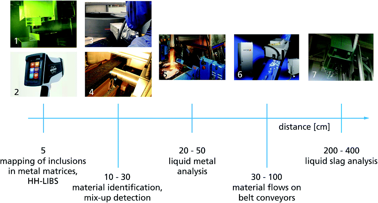 | ||
| Fig. 1 LIBS systems for industrial applications with working distances from a few centimetres to a metre and more. Photos from left to right and top to bottom: high-speed inclusion mapping of steel samples (1), handheld LIBS system (2); identification of coils in a rolling mill (3), identification of blooms on a roller table (4); direct analysis of liquid metal melts (5); high-speed identification and sorting of scrap pieces (6); direct analysis of liquid slag (7). Photos by courtesy of: (1), (3) – Laser Analytical Systems and Automation GmbH, Germany; (2) Bruker Nanoanalytics Division, Kennewick, USA; (4) to (7) – Fraunhofer ILT and its industrial partners. HH-LIBS = handheld LIBS system. | ||
Short WDs of a few centimetres enable narrow focusing of the laser beam and thus a high spatial resolution for chemical analysis as, e.g., applied in industry for multi-element mapping of steel samples.1 Smaller laser pulse energies at small WDs concurrently allow for a downscaling of the LIBS equipment to realise handheld LIBS systems (cf. Section 6). At distances of typically 10–30 cm LIBS systems are identifying steel grades in rolling mills. Here laser pulse parameters are tailored to the task of removing locally non-representative surface layers with thicknesses of several 100 μm prior to bulk analysis.2 Even greater working distances in the range of up to 4 m are required for inline analysis tasks of hot objects such as liquid metals or liquid slag3–5 or up to 1 m for objects moving fast on transport lines.
During the last three to four years two main development directions for industrial LIBS applications become obvious as follows: on the one hand, stationary automated LIBS systems for inline measuring tasks embedded in a process line and, on the other hand, handheld LIBS units mainly for fast positive material identification. Both branches reflect the unique feature of the LIBS method using a purely optical excitation of the measuring object over a distance which makes it predestinated for the fast analysis of metals and oxidic substances. In that sense LIBS becomes an important tool for Industry 4.0 scenarios.
In the same time period a number of publications appeared which are focusing on or giving at least a first perspective for industrial LIBS applications. A query in the Web of Science data base from February 2018 with the search terms (laser-induced breakdown spectroscopy) AND TOPIC: (application) AND TOPIC: (industr*) yields 68 hits for the time span from 2014 to 2018. From these hits, those publications were selected which provide a clear focus on industrial applications or have more than 5 citations thereby omitting those which present a dominantly fundamental study or are restricted mainly to evaluation algorithms or chemometrics or consider research in the microparticle or geological field. The remaining publications can be grouped in terms of the studied substances as follows: (a) analysis/identification of metals or alloys; (b) analysis of raw materials/oxides, recycling materials; (c) others, as e.g. nuclear materials, water.
Group (a) comprises 14 publications.5–18 Noharet et al. described a portable LIBS prototype for online analysis of steel scrap pieces from a production process.6 The LIBS unit is equipped with a low resolving spectrometer and is triggered by a distance measurement based on the triangulation principle; WD is in the range of 0.5 to 1 m. Field tests have been performed with production scrap in a steel plant and at scrap yards. Li et al. studied the quantitative analysis of phosphorus in steel at atmospheric conditions and at a WD of 15 cm.7 With the P I line at 214.91 nm detected by a high-resolving Czerny-Turner spectrometer the phosphorus content in pig iron and low alloy steel was determined yielding limits of detection (LOD) in the range of 9–12 μg g−1. Lorenzetti et al. studied LIBS to monitor the transition layer of steel billets from a casting machine using double pulses and artificial neural networks.8 The WD is presumably 10 cm. A set of samples were taken from such a billet and changes of nickel and chromium concentration from a level of about 1.5 wt% prior to the transition zone down to ≈0.9 wt% after that transition were detected. Merk et al. studied the identification of scrap metal by a LIBS set-up with an echelle spectrometer at a WD of 80 cm.9 Measuring objects were shredded pieces of metals with a single main element such as Ag, Al, Cr, Cu, Fe, Ni, Pb, Sn, Zn and the secondary alloy brass. Sun et al. studied the in situ analysis of steel melts with LIBS and a Cassegrain telescope with WDs of 2.8 m and 4.5 m.5 They used an immersion probe, which dipped into the steel melt. The Cassegrain telescope collected the plasma light into an optical fibre. Tests in a steel plant were conducted to quantitatively determine carbon, silicon and manganese within a measuring time of 1 min. The authors claim to determine carbon without resolving the 247.86 nm carbon line just by use of the partial least square (PLS) method. Zeng et al. studied LIBS via optical fibers to analyse Mn and Ti in pig iron at a WD of 15 cm.10 A laser pulse with a wavelength of 532 nm, a duration of 7 ns, and an energy of 24 mJ is transmitted by a 3 m long optical fiber having a core diameter of 1 mm to the focusing system. LODs shown for Mn and Ti are about a factor of 10 higher than those achieved with conventional LIBS. Noharet et al. studied a LIBS prototype with a compact diode-pumped Nd:YAG laser generating 150 μJ at 7 kHz.11 In a WD of 50 cm tests were performed to measure the analytes Si, Mg and Cu in aluminium scrap samples. Wang et al. gave an overview of applications of LIBS for elemental monitoring of iron and steel making processes.12 Afgan et al. investigated a handheld LIBS instrument (from B&W tek, cf.Table 3, 3rd column) to quantitatively determine 8 elements – among these carbon – in steel.13 With a dominant factor based PLS the average standard deviation for the elements Si, Mn, Ni and Cu in steel are better for LIBS than those achieved with a commercial handheld XRF instrument. Bengtson presented a review comparing LIBS with conventional optical emission techniques (OES) for the analysis of metals.14 He concluded that the extremely simple design of the electric spark source is well suited to automation, which has had a huge impact on routine process control analysis in the metallurgical industry. Whereas for spark OES and glow discharge OES there exist international standards, there is still a lack of such standards for LIBS with implications on a mid-term time scale. Tortschanoff et al. presented application tests of a compact DPSSL for the quantitative analysis of steel.15 The laser source running at 1064 nm delivered 2.5 ns pulses with an energy of 30 mJ. They were focused at WDs of up to 50 mm. Zhao et al. analysed melts of nickel-base alloys at a WD of 1.5 to 2.5 m and ambient pressures of about 5 Pa.16 Coaxial convex and concave mirrors focus the laser beam and collect the plasma radiation. The fiber-coupled echelle spectrometer was temperature stabilised to 30 °C ± 1 °C. Calibration curves of Cr and Al were gained with relative standard deviations in the range from 1.1 to 2.8%. Campanella et al. studied the classification of wrought aluminum alloys by artificial neural networks (ANN) using a laboratory equipment and stationary samples.17 The WD is not specified. The ANN algorithm enabled the separation of wrought aluminum into three groups (cf.ref. 29 which described the identification of eight alloy groups with correctnesses of >95% for secondary aluminum alloy pieces moving with 3 ms−1). Sun et al. have set up a LIBS analyser to monitor the composition of electrolyte and aluminum in aluminum induction cells.18 The goal is to determine a ratio of mass fractions (called BR) as indicator of the acidic state of the electrolyte. The measuring radiation is guided in an argon flushed tube having a length of 750 mm (WD). For solid samples they showed that with a partial least squares regression, the reciprocal of the molecular ratio (1/BR) can be calibrated with a root mean square error of 0.024 in a range of predicted values of 1/BR from 0.75 to 0.9. Quantitative in situ measurements of the liquid electrolyte and aluminum could not be performed due to interferences of the xenon flash lamp (pump source for the Nd:YAG laser) caused by the strong magnetic fields of the induction cells.
Three of four publications in group (b) are treating raw materials and oxides.19–21 Gaft et al. present a LIBS online analyser mounted in an overhead position above a belt conveyor to measure raw materials passing by at a WD of 35 cm.19 As an example phosphorus-bearing apatite and magnesium-bearing dolomite rocks are identified and pebble portions with elevated Mg were moved aside. Further applications discussed are iron sintering mix control and composition stabilisation, magnesite crushed ore composition control and sorting, potash quality control, copper and nickel ores online quality control. Hou et al. developed a method to analyse pressed pellet coal samples at a WD of 10 cm.20 A dominant factor PLS model combined with spectrum standardisation is applied and by this the sample-to-sample RSD of carbon measurements is reduced down to 0.3% from 2.9% for the univariate model. The average measurement error of carbon content is reduced to 0.42% – for a carbon concentration range of 40 to 80% – which meets the national Chinese standard (1%). Ljutic et al. detected phosphorus in industrial oxide materials, such as iron oxide ceramics, slag from industrial steel production, in the UV range using the line P I at 214.91 nm.21 A LOD of 50 ppm is demonstrated for P2O5 in Fe3O4 ceramics and 70 ppm for homogeneous sintered slag samples. A WD is not specified. One publication in group (b) examines recycling materials with LIBS.22 Aquino et al. have applied a commercial LIBS instrument (J200 LIBS system of Applied Spectra, USA) to measure scrap pieces of computer and mobile phones and evaluated the spectra with principal component analysis to determine Au and Ag. No information on the WD is given.
In group (c), Gong et al. studied the remote quantitative analysis of cerium by LIBS to monitor a pyrochemical process using as surrogate sample a mixture of cerium oxide and potassium chloride.23 Excitation by the laser beam and observation of the plasma emission is performed through a plastic shielding window with a thickness of 1.5 cm. The WD amounts to 1.45 m. The plasma emission is collected by a Schmidt-Cassegrain telescope. The authors studied the analytical performance of LIBS with this shielding window which is as well used in a real demonstration nuclear facility. Finally, Karpate et al. studied LIBS as potential tool for industrial/agricultural waste water analysis.24 A pulse of a 532 nm laser is focused at a WD of 10 cm onto a vertically oriented water jet. Water samples consisting of Millipore water doped with copper and silver were studied. For a 1000 ppm solution of these elements, emission lines of copper and silver were identified as well as the hydrogen line at 656 nm and the oxygen triplet lines at 777 nm.
In the subsequent sections we will highlight some new developments at Fraunhofer ILT and RWTH Aachen University (in the period 2014–2017) of automated LIBS systems for inline analysis tasks in industry namely: combined use of inline measured 3D geometry information and LIBS analyses for high-speed sorting tasks of piece goods; sorting of refractories; identification of steel blooms in a rolling mill; inverse production scenario for the recovery of valuable materials from end-of-life electronic equipment. At line or offline LIBS measurements are not considered in these sections.
Finally, we will provide an overview about handheld LIBS systems for industrial applications as e.g. sorting of light metal scraps for recycling purposes. A comparative synopsis of features of these LIBS systems will be presented and discussed.
2. Inline measured 3D geometry information and LIBS analyses for high-speed sorting tasks of piece goods
Short measurement times of LIBS in the order of microseconds allow to measure moving objects. Two classes of moving objects have to be considered: bulk material and singularised objects. Examples for bulk material are granular coal and minerals19,25–28 In that case the laser beam direction is chosen to be stationary, directed from an overhead position downwards to the moving material. Varying height levels are compensated for by an autofocusing optics or a triggered measuring mode, i.e. the laser pulse is emitted while the height level of the bulk material reaches a defined interval.11Singularised objects are e.g. scrap pieces or bricks which shall be sorted in different fractions depending on their chemical composition. In that case the object is tracked with a galvanometer scanner guiding the laser beam to the right position of the object. The 3D geometry of the singularised object is measured upstream of the LIBS measuring volume and this information is evaluated in realtime in order to control the tracking procedure via the scanner. Fig. 2 illustrates this approach.29 The dashed box indicates the measuring volume in which a measuring location for LIBS can be positioned.
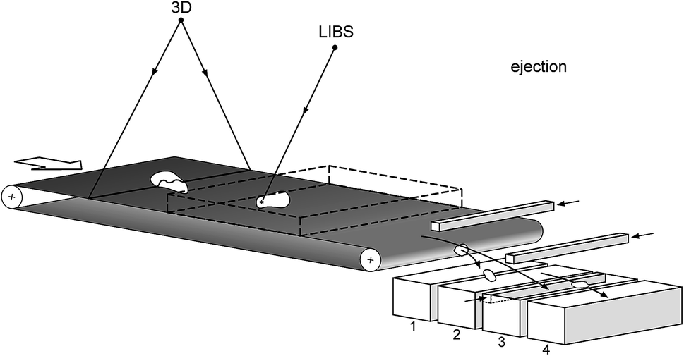 | ||
| Fig. 2 Inline 3D measurement of single objects moving on a belt conveyor, LIBS analysis and sorting to different fractions 1 to 4. | ||
Features of the 1st generation LIBS machines based on this concept are given in Table 1, 2nd column.29 Up to 40 objects can be tracked per second while passing through the measuring volume (typ. 400 × 400 × 120 mm3). Since 2015 Fraunhofer ILT started the development of 2nd generation LIBS machines, called iSort, for singularised object analysis and sorting which now allow for higher speeds of the belt conveyor of up to 5 m s−1 for measuring up to 100 pieces per second. A significantly wider range of object sizes can be handled starting from small pieces of a few millimetres to more than 200 mm large objects. A multi-CCD Paschen-Runge spectrometer covers a wide spectral range with a high spectral resolution for a comprehensive detection of line emissions even in line-rich LIBS spectra.
| 1st generation machine | 2nd generation machine | |
|---|---|---|
| Speed of belt conveyor [m s−1] | ≤3 | ≤5 |
| Working distance [cm] | 60–90 | 40–150 |
| Object rate [s−1] | ≤40 | ≤100 |
| Object sizes [mm] | 25–200 | 3–250 |
| Simultaneously detected elements | 16 | >50 |
Fig. 3 illustrates schematically different industrial application cases of 1st and 2nd generation LIBS machines in the coordinates working distance versus particle size range. The diameters of the circles qualitatively indicate the measuring frequency and the thickness of the boundary circle marks the complexity of the shape (a more simple shape is presented as a thin line, a more complex one as a bold line).
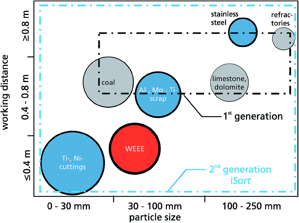 | ||
| Fig. 3 Application fields of inline monitoring and identification tasks by LIBS on moving objects illustrated in the coordinates working distance versus particle size. WEEE = waste electric and electronic equipment. The dashed rectangles indicate the working range of 1st and 2nd generation LIBS machines, cf.Table 1. Filling-in colours are assigned as follows: blue = metals, grey = non-conductive materials, red = mixture of metals and non-metals. | ||
An example for the 3D-measurement of small particles such as cuttings is shown in Fig. 4. A laser line (cf.Fig. 2, “3D”) is projected onto this object while it is passing by on the belt conveyor. The sequence of laser light sections is evaluated to generate a 3D-image, see Fig. 4, right. Within this 3D-image a set of spots is selected having a surface normal within pre-defined angular limits.30 The enlarged rectangle with the marked red spot shows the position preferred for the LIBS measurement. In contrast to other approaches reported so far6,9,28 where the laser beam direction is kept stationary, the configuration illustrated with Fig. 2 and 4 offers a significantly higher quality of measuring results by considering the local geometric features of the measuring objects.
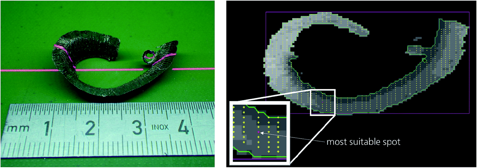 | ||
| Fig. 4 Left: 3D-detection of object topology exemplarily shown for a cutting; right: processed 3D-image of that cutting with determined bounding box and selected spot suited for LIBS analysis based on geometric criteria, see red spot within enlarged white rectangle. Photos: Fraunhofer ILT. | ||
3. Sorting of refractories
Goal of the European project REFRASORT is the development and validation of separation technologies for the high grade recycling of refractory waste.31 Dominant user of refractories is the steel industry where different types of refractory bricks are deployed as lining material for the various furnaces and ladles. At the end of a furnace campaign the lining is dismantled. The generated refractory waste consisting of different types of refractories is so far often used for low grade applications as e.g. road beds or deposited in landfilling. To enable high grade applications the refractories have to be sorted and separated to gain high purity waste streams as valuable resources and refeed for the refractory production.Eight different types of refractory materials are to be distinguished: MgO–C without antioxidant, MgO–C with antioxidant, fired MgO, fired doloma, carbon bonded doloma, fired bauxite, fired andalusite, fired chamotte. The material has an intrinsic inhomogeneity with different grain sizes. The pieces to be handled are in the size range of 60–300 mm and weigh up to 20 kg. For a throughput of 10 t per h one brick has to be identified and sorted per second on average.
Due to their interaction with the processed substances in the furnaces and ladles the surface of the refractory bricks has undergone a chemical and physical modification, i.e. the surface layer is not representative for the bulk composition. Fig. 5 shows a refractory brick with such a modified surface (left; see, e.g., the broken surface at the bottom left having a different visual appearance). LIBS measuring spots penetrating this non-representative layer are shown in the middle of Fig. 5. At the right a detailed view of a single interaction region is shown with a crater diameter in the order of 300 μm. In order to cope with the inhomogeneity of these measuring objects several LIBS measurements are performed per piece. The experimental parameters are as follows: working distance 730 mm, flashlamp-pumped Nd:YAG laser, repetition rate 15 Hz, tailored pulse train consisting of cleaning pulse (350 mJ) and double pulse (200 mJ), interpulse separation of double pulse (DP) Δt = 6 μs, Paschen-Runge spectrometer optics with a Rowland circle of 500 mm, grating 2700 l mm−1, 8 CCD detectors, evaluated spectral range: 240–404 nm, signal integration over the DP.
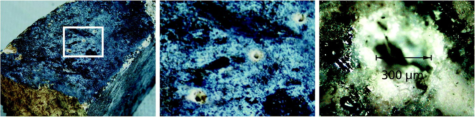 | ||
| Fig. 5 LIBS measuring spots on an end-of-life refractory brick. Left: refractory brick with three LIBS measuring spots, see white rectangle; bottom, left: broken surface of this material. Middle: enlarged detail corresponding to the white rectangle shown in the left image. Right: detailed view of generated crater with a diameter of about 300 μm. Photos: Fraunhofer ILT. | ||
The developed prototype for the sorting of refractory bricks based on inline LIBS measurements is shown in Fig. 6. The pieces are fed to a belt conveyor from the left, are singularised, pass through the 3D and LIBS measurement (cf. Section 2) and are then pushed to different sorting fractions based on the measured and evaluated data.
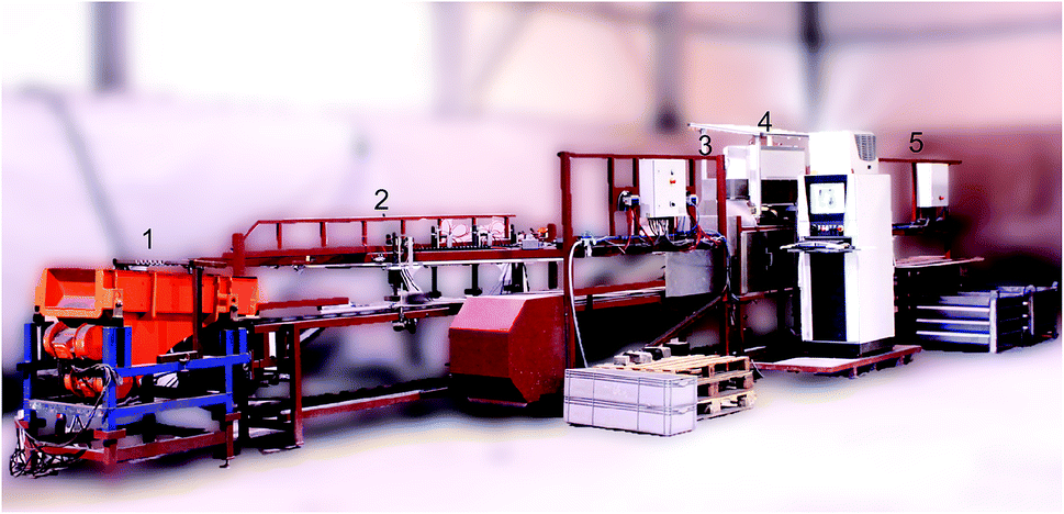 | ||
| Fig. 6 Prototype sorting machine for refractories with integrated LIBS unit (material flow from left to right). (1) feeding, (2) singularisation, (3) 3D-camera, (4) LIBS unit, (5) sorting. Photo: Fraunhofer ILT at the facilities of Orbix, Genk, Belgium. | ||
The results of a 30 t test with mixed used refractories are summarised in Table 2. In the majority the analyte concentrations found in the sorted fractions of magnesite and dolomite fulfill the target specifications, the only exception is a slightly higher content of SiO2 in the dolomite fraction.
| Sorting results | [wt%] | CaO | MgO | SiO2 | Fe2O2 | Al2O3 | LOI |
|---|---|---|---|---|---|---|---|
| Magnesite | Achieved | 2.94 | 93.21 | 1.2 | 1.17 | 0.95 | 1.34 |
| Target | <3.00 | >88 | <3.50 | <2 | <4 | <5 | |
| Dolomite | Achieved | 37.26 | 56.92 | 3.03 | 1.55 | 0.79 | 0.9 |
| Target | <60 | >35 | <2.5 | <2 | <2 | — |
4. Identification of steel blooms in a rolling mill
An inline LIBS measurement at metallic piece goods in a rolling mill is shown in Fig. 7. The fed blooms have surface layers (scale layer and segregation zone) with non-representative surface composition.2,32 The task is a mix-up detection in order to assure that always the correct steel grade is transported to the subsequent furnace and first roll stand. In Fig. 7, left, the bloom is just arriving on the roller table coming from the left, at the bottom the tip of the laser measuring lance is visible. The optical working distance is 300 mm. The bloom is stopped for about 1 minute, while the measuring lance approaches the side face and the laser ablation and LIBS analysis is activated, cf.Fig. 7, right. The approaching of the lance is executed to improve the gas flow conditions in the interaction zone. The stop period of 1 minute lies within the regular feeding rate of the subsequent continuous furnace and thus does not imply any retarding in the production flow.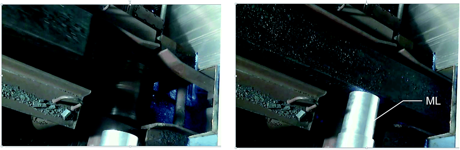 | ||
| Fig. 7 Inline measurement of steel blooms, left: the bloom is transported on a roller table and arriving from the left, right: the measuring lance (ML) is approached to the side face of the bloom, laser irradiation is activated to locally ablate the scale layer and to analyse the bulk composition. Diameter of ML: 170 mm.32 | ||
A process was developed consisting of two phases as follows: (a) local removal of surface layer with cleaning pulses, (b) LIBS analysis using double pulses.2,32 In the first phase a scale layer thickness of 200–600 μm has to be penetrated. Within 20 s an effective crater depth of >2 mm in scale material is achieved.
Fig. 8 shows results of laboratory tests at ground (i.e. non-scaled) and primary-scaled surfaces for steel grades with chromium contents ranging from 0.1 wt% to 17 wt%. The analysis curve (straight line in Fig. 8) was set-up on the basis of 64 ground samples. To characterise the prediction error of Cr concentrations of scaled blooms 53 scaled steel samples were measured. The root mean square error (RMSE) amounts to 0.32 wt% for this set of scaled samples. The developed two-phase measuring process yields about the same results for ground and scaled samples and is thus capable to provide bulk analysis of blooms in their “natural” state with primary-scaled surfaces.
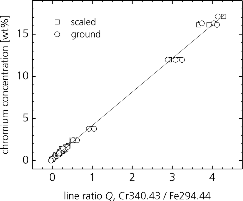 | ||
| Fig. 8 Analysis curve of chromium for scaled and ground surfaces of steel grades deploying a two phase measuring sequence of laser ablation and LIBS analysis.2 | ||
5. Inverse production scenario for the recovery of valuable materials from electronic equipment
Electronic equipment – such as mobile phones (MPH) and electronic boards from computers, servers and switching electronics – comprises a lot of valuable materials such as technology metals. On the other hand their life cycle is becoming shorter and shorter. Thus, the amount of MPHs which are no longer used increases continuously and reaches a level of about 50 million units per year in the European Union (assuming that the European market has a share of about 10% of the world market of 1.9 billions device shipments of mobile phones per year and that the estimated average time of use is 4 years).33This mass flux of valuable material is often lost for the European economy by exports to Africa or Asia.34 If recycled in the EU, the conventional approach is focused on mass stream concepts such as shredder processes, partially followed by magnetic or eddy-current separators and pyrometallurgical procedures to extract the high-value metallic constituents, i.e. gold, silver, palladium and copper from MPHs and printed circuit boards (PCBs). However, a series of critical elements cannot be recovered efficiently or is even lost completely in dust or in residual fractions with high degree of dilution.
How to tackle this mass flow in an efficient way is the focus of the European project “Next generation urban mining – automated disassembly, separation and recovery of valuable materials from electronic equipment”, short title ADIR.35 The goal of ADIR is to demonstrate the feasibility of a key technology for next generation urban mining by selective treatment of the piece goods MPHs and PCBs, e.g., from servers and personal computers, for efficient recovery of all valuable materials instead of using only mechanical – such as crushing or shredding – and metallurgical methods designed mainly for the recovery of the above mentioned metals only.
The overall objective of ADIR is to open the door for next generation urban mining by exploring and demonstrating innovative technologies for automated disassembly, separation and recovery of valuable materials from electronic equipment. The process chain addressed by ADIR is illustrated in Fig. 9.
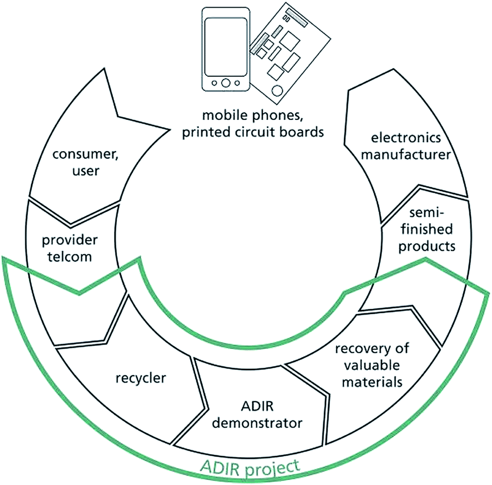 | ||
| Fig. 9 Process chain addressed by the European project ADIR. | ||
The technological concept of the ADIR demonstrator is shown schematically in Fig. 10. A robot and a manipulator are picking single objects from the input stream and feed sequentially the machines I, II and III for selective disassembly of mobile phones and printed circuit boards (PCB) yielding the following sorting fractions: S0 batteries, S1–S3 enriched fractions of valuable materials, RF residual fraction.
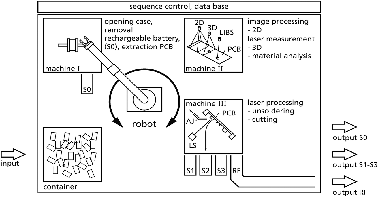 | ||
| Fig. 10 Concept of the ADIR demonstrator. 2D/3D = two/three dimensional measurement of the geometry of PCBs, LIBS = laser-induced breakdown spectroscopy for material analysis, LS = laser source and scanner for unsoldering and cutting, AJ = air jet; S0, S1–S3 = sorting fractions; RF = residual fraction. | ||
The collected end-of-life mobile phones are piled in a container and fed to a conveyor (not shown in Fig. 10). A robot equipped with a camera is picking a single object and positions this piece in a first machine I, where the case of the MPH is opened, the rechargeable battery is removed and put into bin S0 (“sorting fraction zero”). These actions are based on robotic processes, milling actions and potentially combined with pulsed power technology for fragmentation. The printed circuit board is taken out from machine I and a manipulator transfers this PCB to machine II. Machine II performs various measurements at the PCB. It takes 2D and 3D (by laser) images, processes these to identify interesting components potentially containing high amounts of valuable material. LIBS (“material analysis” in Fig. 10) analyses inline the constituents of these components, as e.g. tantalum in capacitors as the basis for extraction and sorting decisions. This information is used to feed a data base and to extract coordinates for the laser beam control to unsolder selectively components from the PCB or to cut out parts of that PCB in machine III.
The disassembled components are discharged to the sorting fractions S1 to S3. After removal of the selected components the residual object goes to a residual fraction (RF).
The principal set-up of machine II is shown in Fig. 11. The PCBs to be measured are positioned in a measuring volume. By a relative movement of a 2D- and a 3D-camera high resolution images of the PCBs are taken. With a scanner optics, a laser beam is then scanned to selected electronic components to measure a chemical information with LIBS.35 The measuring volume has the dimensions 500 × 500 × 60 mm3. A 2D- and a 3D-camera detect high resolution colour images and the 3D-profiles of measuring objects placed inside this volume. By this approach physical as well as chemical information is gained in the same set-up. The LIBS working distance between the last scanner optics and the bottom of the measuring volume amounts to 650 mm.
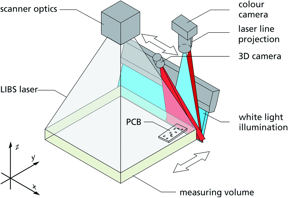 | ||
| Fig. 11 Principal set-up of machine II of the ADIR demonstrator. | ||
For test purposes a raster scan of a complete PCB from a MPH was performed with a step size of 2 mm for the LIBS measurements to determine spectroscopic signals from e.g. tantalum as a function of the xy-position on the PCB. The laser source runs at 1064 nm, 15 Hz with a tailored pulse train consisting of a cleaning pulse (here used for local ablation/drilling) of 300 mJ and a DP of 250 mJ. The interpulse separation of the DP was set to Δt = 6 μs. The laser spectroscopic method enables a multi-element analysis. The measurement time per spot is in the order of 67 ms.
The complete PCB of a mobile phone was rastered several times. By this approach the generated laser craters successively penetrate the housings of the electronic components on the PCB to access the bulk material. Fig. 12 shows on the left side a photograph of the studied PCB (taken from a Nokia 3310 cell phone, size of PCB 108 × 42 mm2) and on the right the result of the 14th LIBS raster scan is shown as false colour plot to indicate tantalum. “14th raster scan” means that at each raster spot a sequence of 13 pulse bursts was irradiated plus the cleaning pulse of the 14th burst and the LIBS signal generated by the last DP is evaluated. An overlay of the geometric 2D-image and the chemical 2D-image yields the identified valuable components.
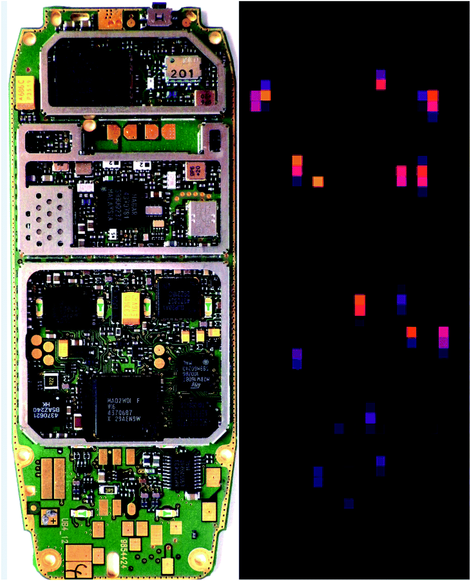 | ||
| Fig. 12 Left: photograph of the front side of a PCB from a MPH, right: raster scan by laser-induced breakdown spectroscopy showing in false colours (orange/red colour presents high intensities) a chemical image of spectroscopic signatures of tantalum.35 | ||
Based on these measurements fed to the data base a component list is generated comprising a set of coordinates to be used for the subsequent processes of selective laser unsoldering and cutting out of the classified electronic components from PCBs.
In 2017 the elementary processes for feeding singularised items, automated disassembly, 2D/3D measurement, laser spectroscopic analysis, laser unsoldering and cutting were worked out and their capability was checked successfully in laboratory scale. Basic hydrometallurgical tests were performed demonstrating that the recovery of elements from sorted fractions such as tantalum, tungsten and neodymium is possible achieving recovery rates of >90%. In the next step the arrangement of interlinked machines will be set-up and integrated to the ADIR demonstrator (2018). The latter will then be tested in field tests at a recycling plant to show the capability of an automatic disassembly, separation and recovery of valuable materials from electronic equipment.
6. Handheld LIBS analysers for industrial application
A reduction of the working distance to a few centimetres allows to reduce significantly the laser pulse energy to generate a LIBS plasma. Instead of hundreds of millijoules as in most cases applied for LIBS, pulse energies in the range of <1 mJ and even less than 100 μJ are sufficient. From a scientific point of view the question is to which extent the pulse energy can be further reduced while still allowing to gain reliable analytic information. The small laser pulse energies imply that only small total ablated masses are transferred to the plasma state and that the noise level is increased thereby. At the same time the short focusing distance enlarges the susceptibility to variations of the working distance or the microtopology of the surface of the measuring object studied. A comprehensive study of the downscaling features of LIBS is still not available.Reduced laser pulse energies and average laser radiant fluxes allow for a strongly reduced size of a LIBS apparatus and thus open the possibility of handheld LIBS analysers. These were studied already more than fifteen years ago for environmental and industrial applications.36,37 A review from 2014 gives an overview of the situation covering person-transportable LIBS devices.38 Recent studies showed that with multivariate spectral data evaluation an analytical performance of handheld LIBS can be achieved being even better than that of handheld X-ray fluorescence (XRF) instruments as demonstrated for analytes in a steel and aluminium matrix.13,39
Quite recently a competitive market arose where various models of handheld LIBS systems are offered and are presented on trade fairs and international conferences as, e.g., the LIBS 2016, the SCIX 2016 and the EMSLIBS 2017. To enable a synopsis of the available equipment a questionnaire was worked out and sent to the providers of handheld LIBS systems in the first half of 2017. The questionnaire comprises 32 questions. From the six providers addressed three returned the filled in questionnaire. Some provided detailed information on concentration ranges of analytes and limits of detection for different matrices. For simplicity this information is skipped here in order to enable the aspired synoptic character. If no data are provided via the questionnaire public available data from the web-pages of the providers are taken as well as information provided by these suppliers on exhibitions and vendor sessions. Table 3 shows the synopsis of data of handheld LIBS systems.
| Manufacturer | Bruker | B&W Tek | Oxford | Rigaku | Sci-Aps | TSI |
|---|---|---|---|---|---|---|
| Questionnaire response provided Model, product name | No | Yes | Yes | No | Yes | No |
| EOS | NanoLIBS | Vulcan expert (Vulcan smart) | KT-100 | Z-100 (Z-300) | ChemLite 4235 | |
| Laser class of handheld LIBS System laser type | 3B | 3B | 3B | 3B | 3B | 1M |
| Nd:YAG | DPSSL | Passively Q-Switched laser | — | Q-switched DPSSL | — | |
| Laser wavelength [nm] | 1064 | 1064 | 1064 | 1064 | 1064 | 1574 |
| Repetition rate of laser [Hz] | 5000 | 1000–5000 | 7500 | — | 50 | — |
| Average laser power [mW] | 100 | <200 | <450 | — | 250 | — |
| Laser pulse duration, FWHM, [ns] | — | — | 2–4 | — | 1.9 | — |
| Laser beam profile | — | — | Circular | — | Elliptic | — |
| Single laser spot size on target [μm] | — | ∼30 | −25 | — | 50–70 | >200 |
| Peak irradiance [GW cm−2] | >1 | Several GW cm−2 | 0.1 | — | ∼200 | — |
| Cleaning of surface of measuring object | — | None | None or up to 1–3 pre-burns per user selection | Auto-surface preparation, ∼1 s | User selectable pre-burn; typ. 10 cleaning pulses/location | Built-in cleaning mode |
| Spatial averaging | Rastering scan | Raster | Linear scan | — | 2D-rastered; e.g. 6 spots separated by 200 μm | No moving parts |
| Effective interrogated target surface | — | 300 μm | 2 × 0.1 mm2 | — | 2.5 × 2.5 mm2 | — |
| Typical time for a measurement[s] | — | 0.3 | 1 | ∼2 | 1–3; 9–12 for 0.2% carbon delta | 1–3 |
| How many measurements à 2 s can be conducted with a fully charged battery? | — | — | Full day operation (8 hours) in continuous use, 5 second measurement cycle (1 s measurement + 3 s break) | — | >1000@50 Hz; run time 4 h, high duty cycle; 8 h, low duty cycle | — |
| Capacity of battery [Ah], voltage [V] | 6.8 Ah, 7.2 V; 1 battery for 6 h run time; 2000 pulses per charge | 12 V DC | 6.2 Ah, 7.2 V | 5 h operation | 3.4 Ah, 14.4 V | — |
| Spectral range of spectrometer [nm] | 170–720 | 200–800 | 240–510 | 220–480 | 190–620 (190–950) | — |
| Spectral resolution [nm]@x nm | High resolution for e.g. Ti | 0.3 | 0.3 | <0.2 | 0.14@250 nm | — |
| Detector type, number of pixels | — | CCD | CCD, 3600 | CCD | CCD, 4096 (6144) | — |
| Time-gated detection | No | No | No | — | Yes, user selectable gate delay: 0 ns, 250 ns to 100 μs | — |
| Read-out frequency of detector [Hz] | — | — | 100 | — | 50 | — |
| Available calibration for metal analysis | Al, Ti, Mg | — | Low alloy steel, tool steel, stainless steels, Ti, Co, Ni, Cu, Zn, Sn, Pb, Al, Mg + pure element ID for Ag, Au, Bi, Cd, Cr, Ge, Hf, In, Mn, Mo, Nb, Pd, Sb, Si, Ta, V, W, Y and Zr | — | Aluminium, copper/brass, cobalt, low-alloy steel, stainless steel, nickel, titanium, tin; others can be added by request | Al, Mg, Ti base metals |
| Limit of detection [μg g−1] | In ti: 700–3000 | — | 200–5000, depending on element and matrix | — | Low alloy steel: C 800–1200 (preparation of sample by grinding; five valid LIBS tests); other analytes in most alloys matrix types: 0.01 to 0.5 m%; analytes in Al: 10 μg g−1 to 0.3 m%. | ∼100 for most elements |
| In Al: 200–2000 | ||||||
| In Mg: 200–3000 | ||||||
| Available calibration for non-metals analysis | — | Raw material identification | None | — | Geochem (rock), iron ore, cement, soil | — |
| Positive material identification (PMI) | Yes, alloy grade ID; light element alloys; fingerprints ID | Yes for salts | Yes, all common alloy bases | PMI for aerospace and petrochemical | Yes, grade matching in any alloy base | Yes |
| Camera included | No | No | Yes, measured spot (Vulcan smart optional) | Yes | Yes, viewing field 3 × 3 mm2 | No |
| Protection class | — | IP 54 | IP 54 | IP 54 | IP 52 | — |
| Further standards applicable to the device | — | Software is 21 CFR pt 11 compliant | MIL-STD-810G compliant | MIL 810-G; FDA 1040 compliant | — | — |
| Operating temperature range | 10–40 °C | 0–40 °C | 0–40 °C | 5–40 °C | 5–40 °C | — |
| Market launch, month/year | 01/2015 | 03/2016 | 1/2017 | 2015 | 2/2014 | — |
| Major revision of product features/specs | — | 09/2016 | None | — | 2/2016 | — |
| Major application field | Metal sorting and valuation, fingerprint ID, PMI, light element capability; Li, Be, Mg, Al, Si | Pharmaceutical ID | PMI QA/QC, scrap sorting, aluminium alloys, stainless steels and all common alloy groups | Identification of: Al grades (1100, 6061, 6063); stainless steel, nickel alloys, titanium alloys | Scrap metal recycling, alloy PMI, alloy fabrication quality control, geology, soil, others | Scrap PMI, QC |
| Unique selling point | Compared to XRF, light element analysis, 10× faster, 400+ grade definitions | FDA 21 CFR pt 11 compliant software; high repetition rate laser | Fast, very rugged (IP54, MIL-STD-810G), analytical performance, cloud based data management and reporting | “kick-stand” foot | High power, argon purge, 2D raster, high repetition rate, gating, mapping, liquids, complete parameter selection by user, video aiming, powerful calibration software suite (for Z-300: with extended wavelength range additionally: H, Li, K, O, N, S, Cl, Br) | Light metals identification and analysis; sensitive quantification of light elements; eye-safe laser technology |
| Weight | 2.4 kg incl. battery | 1.8 kg | 1.5 kg | 1.5 kg | 1.85 kg without battery (1.95 kg without battery) | — |
| Other features | Air-flow optics shield | No Ar purge; GPS tracking | Ar purge, canister in handle for 600 tests | Ar free | ||
| Miscellaneous, other product names | EOS 500 | ChemLogix: Alloy manager software |
The typical handheld LIBS system is classified as a laser device of class 3B, has a weight around 2 kg and covers a spectral range of several hundred nanometres with a spectral resolution of 0.1 to 0.3 nm. Most of these systems use a rastering scan to provide a spatial averaging. The stated available calibrations mostly refer to the analysis of metals such as light metals, non-ferrous alloys and different steel grades and reveal the focus of these systems on industrial applications. Addressed use cases are positive material identification (PMI), scrap and metal sorting. Unique selling points stated are light element analysis, speed of analysis and the very rugged design.
The average laser radiant flux lies in the range of 100 to 450 mW. Two approaches are followed concerning the repetition rate: ≥1 kHz or 50 Hz. In the first case pulse energies are in the range <100 μJ, in the second they amount to 5 mJ (cf. column for Sci-Aps). A simple ablation test performed with the Sci-Aps system using as target a 2 €-coin showed crater depths in the range of 2 to 5 μm per pulse.
The providers have initiated a new market for LIBS systems which has the perspective to open a broad industrial use beyond the niche applications so far realised with stationary LIBS systems.
With these apparative possibilities the challenge for the community of LIBS researchers is to investigate the limits of downscaled laser pulse energies for a given analytical uncertainty.
7. Conclusion
During the last four years two main development directions for industrial LIBS applications became obvious. On the one hand, stationary automated LIBS systems were developed and some of these were already put into routine use at production lines. They gain inline chemical information for monitoring and control purposes on material dependent processes. Examples were shown for high-speed sorting tasks, sorting of refractories, identification of steel blooms and the characterisation of printed circuit boards for the selective recovery of valuable materials. Working distances in the range of 10 cm to about 1 m are predestinated for inline measuring tasks by automated LIBS systems in production and process lines since this allows for a simplified integration in the industrial environment considering the size and physical state of the measuring object. In that sense LIBS can contribute significantly to Industry 4.0 scenarios.On the other hand, at working distances of a few centimetres the capability of downscaling of the laser parameters for LIBS becomes important. The small crater depths coming along with the use of small pulse energies pose a limit for the penetration of non-representative surface layers. Further R&D efforts are required to explore the limits of small laser pulse energies for quantitative LIBS analyses and to develop methodical approaches to overcome concomitant reductions of the analytical performance.
For short working distances the reduced sizes of laser sources have stimulated the evolution of handheld LIBS systems in a competitive market which will lead to lot sizes of LIBS units much higher than those achieved so far for stationary LIBS machines. A multitude of industrial applications of handheld LIBS systems is expected also to be pushed forward by the progress of spectral data evaluation.
Conflicts of interest
There are no conflicts to declare.Acknowledgements
A part of the presented results were gained within the frame of a series of national and international R&D projects. The authors wish to express their thanks for co-financing of these projects by industrial partners, the Federal Ministry of Education and Research of Germany, the Federal Ministry for Economic Affairs and Energy, the European Commission and the Fraunhofer-Gesellschaft zur Förderung der angewandten Forschung e.V. The project concerning the identification of steel blooms, short title “Laser-ID”, was co-financed by the European Union, the Federal State of North-Rhine Westphalia: “Europäischer Fonds für regionale Entwicklung (EFRE) für NRW”, grant agreement No. 603809. The project ADIR has received funding from the European Union's Horizon 2020 research and innovation programme under grant agreement No. 680449.References
- F. Boué-Bigne, Spectrochim. Acta, Part B, 2016, 119, 25–35 CrossRef.
- C. Meinhardt, V. Sturm, R. Fleige, C. Fricke-Begemann and R. Noll, Spectrochim. Acta, Part B, 2016, 123, 171–178 CrossRef CAS.
- V. Sturm, R. Fleige, M. de Kanter, R. Leitner, K. Pilz, D. Fischer, G. Hubmer and R. Noll, Anal. Chem., 2014, 86, 9687–9692 CrossRef CAS PubMed.
- S. Hudson, J. Craparo, R. De Saro and D. Apelian, Metall Ital., 2016, 6, 5–8 Search PubMed.
- L. Sun, H. Yua, Z. Cong, Y. Xina, Y. Li and L. Qi, Spectrochim. Acta, Part B, 2015, 112, 40–48 CrossRef CAS.
- B. Noharet, E. Zetterlund, O. Tarasenko, M. Lindblom, J. Gurell, A. Bengtson and P. Lundi, Proc. SPIE, 2014, 8992, 89920R CrossRef.
- C. Li, Z. Zou, X. Yang, Z. Hao, L. Guo, X. Li, Y. Lu and X. Zeng, J. Anal. At. Spectrom., 2014, 29, 1432–1437 RSC.
- G. Lorenzetti, S. Legnaioli, E. Grifoni, S. Pagnotta and V. Palleschi, Spectrochim. Acta, Part B, 2015, 112, 1–5 CrossRef CAS.
- S. Merk, C. Scholz, S. Florek and D. Mory, Spectrochim. Acta, Part B, 2015, 112, 10–15 CrossRef CAS.
- Q. Zeng, L. Guo, X. Li, C. He, M. Shen, K. Li, J. Duan, X. Zeng and Y. Lu, J. Anal. At. Spectrom., 2015, 30, 403–409 RSC.
- B. Noharet, C. Sterner, T. Irebo, J. Gurell, A. Bengtson, R. Vainik, H. Karlsson and E. Illy, Proc. SPIE, 2015, 9369, 936904 CrossRef.
- Z. Wang, Y. Deguchi, F. Shiou, J. Yan and J. Liu, ISIJ Int., 2016, 56, 723–735 CrossRef CAS.
- M. Afgan, Z. Hou and Z. Wang, J. Anal. At. Spectrom., 2017, 32, 1905–1915 RSC.
- A. Bengtson, Spectrochim. Acta, Part B, 2017, 134, 123–132 CrossRef CAS.
- A. Tortschanoff, M. Baumgart and G. Kroupa, Opt. Eng., 2017, 56, 124104 CrossRef.
- T. Zhao, Z. Fan, F. Lian, Y. Liu, W. Lin, Z. Mo, S. Nie, P. Wang, H. Xiao, X. Li, Q. Zhong and H. Zhang, Spectrochim. Acta, Part B, 2017, 137, 64–69 CrossRef CAS.
- B. Campanella, E. Grifoni, S. Legnaioli, G. Lorenzetti, S. Pagnotta, F. Sorrentino and V. Palleschi, Spectrochim. Acta, Part B, 2017, 134, 52–57 CrossRef CAS.
- L. Sun, H. Yu, Z. Cong, H. Lu, B. Cao, P. Zeng, W. Dong and Y. Li, Spectrochim. Acta, Part B, 2018, 142, 29–36 CrossRef CAS.
- M. Gaft, L. Nagli, Y. Groisman and A. Barishnikov, Appl. Spectrosc., 2014, 68, 1004–1015 CrossRef CAS PubMed.
- Z. Hou, Z. Wang, T. Yuan, J. Liu, Z. Li and W. Ni, J. Anal. At. Spectrom., 2016, 31, 722–736 RSC.
- E. Ljutic, P. Kolmhofer, H. Heilbrunner, B. Praher, N. Huber, R. Rössler, H. Wolfmeir, E. Arenholz, J. Heitz and J. Pedarnig, Rom. Rep. Phys., 2014, 66, 1155–1164 Search PubMed.
- F. Aquino, J. Santos, R. Carvalho, J. Coelho and E. Pereira-Filho, RSC Adv., 2015, 5, 67001–67010 RSC.
- Y. Gong, D. Choi, B. Han, J. Yoo, S. Han and Y. Lee, J. Nucl. Mater., 2014, 453, 8–15 CrossRef CAS.
- T. Karpate, M. Shameem, R. Nayak, V. Unnikrishnan and C. Santhosh, Proc. SPIE, 2016, Vol. 9893, 989317 CrossRef.
- R. Noll, C. Fricke-Begemann, M. Brunk, S. Connemann, C. Meinhardt, M. Scharun, V. Sturm, J. Makowe and C. Gehlen, Spectrochim. Acta, Part B, 2014, 93, 41–51 CrossRef CAS.
- M. Gaft, L. Nagli, I. Fasaki, M. Kompitsas and G. Wilsch, Spectrochim. Acta, Part B, 2009, 64, 1098–1104 CrossRef.
- H. Xia and M. Bakker, TALANTA, 2014, 120, 239–247 CrossRef CAS PubMed.
- Product MopaLIBS of the company Secopta, Berlin, http://www.secopta.de/produkte/mopalibs.
- P. Werheit, C. Fricke-Begemann, M. Gesing and R. Noll, J. Anal. At. Spectrom., 2011, 26, 2166–2174 RSC.
- European Patent EP 1 520 165 B1, method and device for carrying out emission spectrometry, Fraunhofer-Gesellschaft zur Förderung der angewandten Forschung e.V., 2008/12.
- REFRASORT – Innovative separation technologies for high grade recycling of refractory waste using non destructive technologies, final report summary, Grant Agreement no. 603809, http://cordis.europa.eu/result/rcn/194560_en.html.
- V. Sturm, C. Meinhardt, R. Fleige, C. Fricke-Begemann and J. Eisbach, Spectrochim. Acta, Part B, 2017, 136, 66–72 CrossRef CAS.
- https://www.statista.com/statistics/265878/global-shipments-of-pcs-tablets-ultra-mobiles-mobile-phones/ .
- M. Kaya, Waste Manage., 2016, 57, 64–90 CrossRef CAS PubMed.
- R. Noll, R. Ambrosch, K. Bergmann, S. Britten, H. Brumm, A. Chmielarz, S. Connemann, M. Eschen, A. Frank, C. Fricke-Begemann, C. Gehlen, T. Gorewoda, M. Guolo, W. Kurylak, J. Makowe, G. Sellin, M. Siguier, A. Tori and F. Veglia, Proc. Eur. Metall. Conf., 2017, 2017, 799–816 Search PubMed.
- K. Yamamoto, D. Cremers, M. Ferris and L. Foster, Appl. Spectrosc., 1996, 50, 222–233 CrossRef CAS.
- F. Hilbk-Kortenbruck, M. Höhne, R. Noll, M. Freit, J. Joosten and H. Falk, Proc. 9. Anwendertreffen Röntgenfluoreszenz- und Funkenemissionsspektrometrie, 2002, pp. 59–69 Search PubMed.
- J. Rakovský, P. Čermák, O. Musset and P. Veis, Spectrochim. Acta, Part B, 2014, 101, 269–287 CrossRef.
- M. Scharun, C. Fricke-Begemann and R. Noll, Spectrochim. Acta, Part B, 2013, 87, 198–207 CrossRef CAS.
| This journal is © The Royal Society of Chemistry 2018 |