 Open Access Article
Creative Commons Attribution 3.0 Unported Licence
Molecular dynamics simulations of carbon nanotube porins in lipid bilayers†
Martin
Vögele
 a,
Jürgen
Köfinger
 a and
Gerhard
Hummer
 *ab
*ab
aDepartment of Theoretical Biophysics, Max Planck Institute of Biophysics, Max-von-Laue-Str. 3, 60438 Frankfurt am Main, Germany. E-mail: gerhard.hummer@biophys.mpg.de; Tel: +49 69 6303 2501
bInstitute for Biophysics, Goethe University, Frankfurt am Main, Germany
First published on 11th April 2018
Abstract
Artificial channels made of carbon nanotube (CNT) porins are promising candidates for applications in filtration and molecular delivery devices. Their symmetric shape and high mechanical, chemical, and thermal stability ensure well-defined transport properties, and at the same time make them ideal model systems for more complicated membrane protein pores. As the technology to produce and tune CNTs advances, simulations can aid in the design of customized membrane porins. Here we concentrate on CNTs embedded in lipid membranes. To derive design guidelines, we systematically studied the interaction of CNT porins with their surrounding lipids. For our simulations, we developed an AMBER- and Lipid14-compatible parameterization scheme for CNTs with different chirality and with functional groups attached to their rim, and a flexible coarse-grained description for open-ended CNTs fitting to the MARTINI lipid model. We found that the interaction with lipid acyl chains is independent of the CNT chirality and the chemical details of functional groups at the CNT rims. The latter, however, are important for the interactions with lipid head groups, and for water permeability. The orientation and permeability of the pore are mainly determined by how well its hydrophobicity pattern matches the membrane. By identifying the factors that determine the structure both of isolated CNTs in lipid membranes and of CNT clusters, we set the foundation for a targeted design of CNT–membrane systems.
1 Introduction
The unique properties of carbon nanotubes (CNTs) have attracted a lot of interest, and a large number of possible CNT applications have been proposed. A particularly interesting property is their excellent water conductivity, as predicted from simulations1 and confirmed in experiments.2,3 Inserted as artificial channels into lipid membranes4–7 or assembled into densely packed hexagonal arrays,8–10 CNT porins are candidates for drug delivery11,12 and filtration.13–15 Their transport properties show similarities with those of protein channels,16,17 including a high ion selectivity4,18–23 and an ultrafast proton transport mechanism.24–27Simulations were able to investigate water transport1,28–30 and ion conductivity through CNTs,18,19,31 and the factors that govern the membrane embedding and pore permeability.32–45 CNTs can be tuned, e.g., by variations in their diameter18,19,31 or by adding functional groups within the CNT31 or at the ends.43,46,47 As another critical but difficult-to-measure property controlling the orientation and permeability of the pores, CNT–lipid interactions have also been studied via computer simulations.12 The simulations, while mostly focused on insertion and permeation,33–45 also shed light on adsorption of free lipids on the CNT surface48,49 and on CNTs as vesicle-fusion devices.50 It has been found that, upon insertion, CNTs and bundles of them strongly perturb the membrane.51–53 Lipid interactions of a CNT porin and the resulting lipid density distribution have also been compared to that of biological nanopores.54
Here we study the impact of different kinds of CNT porins on the surrounding membrane, and of different lipid environments on the membrane embedding of the CNTs. In simulations at fully atomistic resolution (see Fig. 1 for a snapshot), we focus on the influence of CNT chirality and end-group functionalization on CNT–lipid interactions and lipid organization. To test for lipid sensitivity, we also explore different lipid types. In coarse-grained simulations, we study the effect of the length and diameter of the CNTs. In atomistic simulations, we determine the dependence of the water permeability on the CNT chirality and rim functionalization. The results provide useful guidance for the computer-aided design of specific porins.
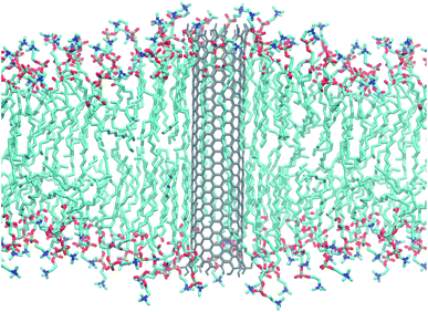 | ||
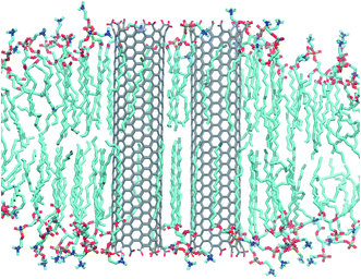
| Fig. 1 Armchair CNT of 4.5 nm length with COOH end termination embedded in a POPC lipid membrane. Snapshot taken from an atomistic simulation after 240 ns. Water not shown for clarity. | ||
The atomistic and coarse-grained simulation schemes and methods we develop are flexible and compatible with the existing AMBER and MARTINI force fields. They make it possible to study arbitrary porin geometries and various functionalizations as well as interactions with other molecules parameterized in the respective force fields.
2 Computational methods
2.1 Atomistic simulations
We performed atomistic molecular dynamics simulations of single CNTs, pairs, and groups of four in lipid membranes. We created CNTs with four different functionalizations (COOH, COO−, OH and H-only) in zigzag and armchair configurations with three different lengths of the CNTs (4.0 nm, 4.5 nm 5.0 nm) and simulated them in a POPC membrane. To test for the effects of different lipids, we simulated a CNT of 4.5 nm with OH functionalization in membranes of DOPC, DPPC and POPE. In addition, we simulated pairs and quartets of CNTs in POPC using different starting conditions. We used the Lipid14 force field55 in Amber 14 (ref. 56) and derived GAFF-style57–59 models for the differently functionalized CNTs.The GAFF parameters57 were assigned to the nanotubes by running acpype59 on these structures. Partial charges were defined by a standard scheme, which was parameterized as follows. For several nanotubes with different functionalizations and of different (small) sizes, the geometry was optimized and restraint electrostatic potential (RESP) charges67 were calculated using R.E.D. (version III.52) with Gaussian 09 (RESP-A1: HF/6-31G* Connolly surface algo., 2 stage RESP fit qwt = 0.0005/0.001). The structures from BuildCstruct were either used directly as input, or (if the algorithm did not converge) a short atomistic energy minimization with non-optimized partial charges was performed.
We averaged and rounded the charges to two significant digits (under the constraint to preserve the total charge of a functional group of 0 or −1, respectively) such that all identical functional groups have the same charge distribution and such that all charges beginning from the third carbon ring are assigned a value of zero. This is a good approximation according to our results as well as to results obtained by DFT calculations,68 where partial charges of pristine single wall CNTs have been shown to concentrate on the edges and decrease rapidly towards the middle of the tube. Our results indicate that this is also true for functionalized CNTs.
2.2 Coarse-grained simulations
We simulated single CNT porins embedded in lipid membranes using Gromacs.69 The lipid membrane was set up with the insane.py70 tool. We varied the CNT in both length and diameter and repeated the study for three different functionalizations at the rim (SNda, SP3, and none), and simulated them all in a POPC membrane. In an additional study, we simulated one SNda-functionalized CNT in POPC/DOPC membranes of various size. Details on the procedure can be found in the ESI† and the force fields are described below.![[thin space (1/6-em)]](https://www.rsc.org/images/entities/char_2009.gif) :
:![[thin space (1/6-em)]](https://www.rsc.org/images/entities/char_2009.gif) 1 mapping. Water is accordingly modeled with one bead for four water molecules.
1 mapping. Water is accordingly modeled with one bead for four water molecules.
Due to the flattening of the energy landscape, the overall dynamics in coarse-grained simulations are accelerated. The developers of the MARTINI force field recommend a scaling factor of four.71 This means that the actual time is (approximately four times) longer than the simulated time.
For the carbon-only region of the nanotube, we chose the CNP interaction sites, which have already been used for fullerenes73 and for capped nanotubes.53 As in the latter model, end-group functionalization is modeled by replacing the CNP bead type with a more polar one. We used beads of the types SNda (weakly polar) and SP3 (strongly polar). An example of this configuration is shown in Fig. 2.
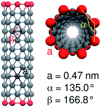 | ||
| Fig. 2 MARTINI model of a CNT with 12 × 8 nonpolar CNP beads and polar end groups, with angles and bond lengths indicated. | ||
The bonded interactions between neighbor atoms were chosen as in the model for the capped nanotubes53 with a bond length of 0.47 nm and a force constant of 5000 kJ mol−1 nm−2.
For the angle potentials along the rings, we used a force constant of 350 kJ mol−1 rad−2 and an equilibrium angle of
 | (1) |
We accounted for the stiffness along the tube by introducing harmonic improper dihedral angle potentials that maintained the angle β between two triangles with a force constant of 350 kJ mol−1 rad−2, as shown in Fig. 2. As an equilibrium value, we get
 | (2) |
2.3 Analysis
The python scripts used to analyze the simulations are publicly available. The scripts for the atomistic simulations can be found at https://github.com/bio-phys/cnt-lipid14-analysis and those for the coarse-grained simulations at https://github.com/bio-phys/cnt-martini-analysis. Both extensively use the MDAnalysis74,75 python package. | (3) |
 | (4) |
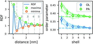
To estimate the influence of the CNTs on the lipid ordering, we assigned the order parameter of each lipid acyl chain (averaged over all atoms) to the annular lipid shell to which the tail belongs. We used the minima of the RDF as cut-off distances to separate the shells. To get a bulk value for comparison, we simulated a patch of a pure lipid membrane of 288 POPC lipids.
In coarse-grained simulations, a different definition of the order parameter has to be used. There are no hydrogen atoms and therefore no information on CH bonds. A rough estimate can be provided by the angle αj between the membrane normal and bond j connecting two MARTINI beads. This angle is supposed to be averaged over various C–C bonds and roughly perpendicular to the average orientation of a C–H bond. Due to the symmetry of cos2(x), the coarse-grained order parameter
 | (5) |
 | (6) |
The net permeation n(t) is then obtained by integration with the initial condition n(0) = 0. In equilibrium simulations, the trajectory of n(t) shows random-walk behavior. Its mean-squared displacement (MSD) is linear in time and defines a diffusion coefficient Dnvia
| 〈n2(t)〉 = 2Dnt. | (7) |
An increase of n(t) by one means that one water molecule has been transported in the direction of positive z. Using the fluctuation–dissipation theorem,76 the pore permeability pf is obtained as pf = vWDn with vW ≈ 29.7 Å3 being the volume of a water molecule.
3 Results and discussion
3.1 Interaction of single CNTs with lipids
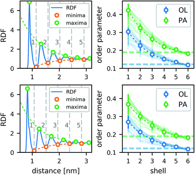
The lipids form a strong annular shell around the CNT. We evaluated the radial distribution function (RDF) with respect to the principal axis of the CNT for the carbon atoms of the lipid acyl chains in all simulations containing only one CNT (Fig. 3). A pronounced ring-like multilayer structure is clearly visible, with a strong first peak of the RDF followed by up to about five further maxima. In accordance with recent simulations comparing different biological and biomimetic nanopores,54 this structuring is a consequence, first, of the tight lipid–CNT interactions and, second, of the relatively smooth surface of the CNT. Because we calculated the RDF with respect to the main CNT axis, to minimize the effect of CNT tilting, we could resolve the first very pronounced peak in more detail. This peak shows a distinct shoulder on the far side. Inspections of the structures showed that this shoulder is caused by acyl chains adhering to the CNT surface only partly while the rest is kept close to the tube, but not in direct contact with it. The amplitudes of all further maxima and minima decrease exponentially with the distance from the CNT (Fig. 3), and remain visible up to the fifth layer.In contrast to typical transmembrane proteins, the CNTs increase the lipid order in their proximity. For all CNTs, the order parameters in the first four shells around them were significantly higher than the respective bulk values. In the first shell, they even became twice as high as in the bulk. Both effects, the pronounced lipid shells as well as the increase of the order parameter, were observed with minimal differences for the two CNT chiralities studied, and for every type of functional group at the rim.
In tests for possible artifacts of the finite box size (see ESI†), no dependence of the lipid layering on the box size was found. However, the increase in the order parameter near the CNT might be overestimated by ≈0.03–0.05 in the typical simulation boxes of this study (7–10 nm). In narrow boxes, lipid ordering around CNTs is more pronounced, likely enhanced by periodic boundary conditions. Therefore, caution is advised also in studies of lipid shells formed around membrane proteins in simulations using typical box sizes.
Due to its regular hydrophobic surface and its mostly upright position, a CNT binds strongly to lipids and orders them in distinct rings. In the immediate vicinity of the CNTs, the lipids adopt structures not typical of a liquid-disordered phase. Instead, the lipids seem to form a strong coat around the nanotube, especially those in the very first shell. Annular lipid shells are well-known for membrane proteins,78,79 but the protein coating is not as strong and regular as seen here.54 The effects of such lipid shells can be observed here in pure and unperturbed form. We can therefore consider CNTs as idealized models for the study of annular-lipid structures forming around membrane proteins (especially barrel-shaped proteins), and possibly as models for the induction of an “orderphilic” transition.80
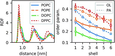
For different lipid types, the density of annular rings differs slightly but the main characteristics are preserved (Fig. 4). Those lipids that would be highly ordered even without the CNT show more pronounced maxima in the RDF (e.g., DPPC). The less-ordered lipids (e.g., DOPC) show a stronger shoulder in the first peak. As this shoulder occurs for POPC but not for POPE, we conclude that it does not stem directly from an inherent property of the lipid acyl chains (which are the same in both lipids), but from the overall order. The most distinct behavior is seen for DPPC. Due to its two palmitoyl tails, it is substantially more ordered. It not only forms a dense layer around the CNT but also all further density peaks are sharper and their distance is a bit shorter than for the other lipids. By and large, however, the behavior is qualitatively the same for all lipid types.
3.2 CNT functional end groups
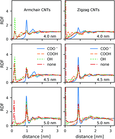
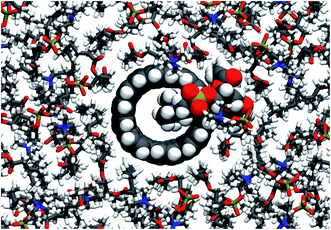
In contrast to the lipid acyl chains, the RDFs of the lipid head groups show a strong dependence on the rim functionalization of the CNT. For armchair and zigzag CNTs, the RDFs show a common trend (Fig. 5). The head-group density at the edge of the CNT increases with the length of the CNT. The longer tubes order the polar head groups around them more strongly, and keep them away from the CNT openings. For short tubes without or with only weakly polar end-functionalization, the head groups can bend over the edge of the CNT (Fig. 6), especially when the CNT is tilted. This effect is represented in the RDF as a peak in the region where r is smaller than the radius of the CNT. CNTs with carboxylate (COO−) functionalization, carrying a negative charge, manage best to prevent the head groups from bending over the rim and into the opening. Depending on the purpose of the membrane, charged rims might be more or less desirable. In any case, polar functional groups can prevent the pore from closing by lipid blockage.3.3 Comparison to coarse-grained simulations
The structure of the lipid shells seen in the atomistic simulations is well reproduced in the coarse-grained MARTINI model simulations (Fig. 7). The distances and widths of the distinct shells are in excellent agreement. Lipid structuring extends out to five layers in both models. Even though the first peak is less sharp in MARTINI (which is to be expected in a coarse-grained model), it is still higher than that extrapolated from the exponential behavior of the outer shells. The MARTINI model is therefore suitable to model the effects of CNT–lipid-tail interactions.The order parameters in the MARTINI model show the same trend as in the atomistic model, but it is less pronounced. The order parameter is strongly increased in the first two shells around the CNT and slightly increased up to the fifth shell. The difference between the models is not dramatic as, by definition, the MARTINI order parameter is not able to capture the ordering effect on single CH bonds, but only the much coarser general orientation of the tail.
As in the atomistic simulations, no dependence of lipid layering on the box size was found for the MARTINI model (see ESI†). In contrast to the atomistic model, no trend was found for the order parameter. This is not surprising as the overall ordering effect is less pronounced in the MARTINI model. The box sizes in the MARTINI simulations (≈15 nm) are therefore sufficient.
We note that the CNT chirality and the specific details of the functional groups are not resolved within our coarse-grained MARTINI model. However, the MARTINI CNTs reproduce well the structural properties found in the atomistic simulations. These are dominated by geometry and the hydrophobic effect.
3.4 Tilting of CNTs
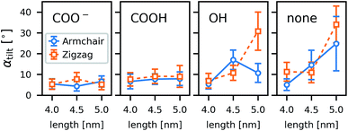
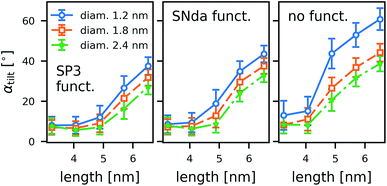
As a general trend in the atomistic simulations, the longer tubes tend to tilt more with respect to the membrane normal than the shorter ones and polar functional groups prevent tilting (Fig. 8). These two observations can be explained by the CNTs striving to minimize hydrophobic mismatch, i.e., the contact of the hydrophobic CNT surface with water or hydrophilic lipid head groups.Even though we can identify trends within a large number of simulations, the individual simulations are too short for tilting to be fully equilibrated. A study on one CNT (armchair, 5 nm, COOH) in differently sized boxes (see ESI†) indicates that the tilting is only marginally affected by the finite size and rather under- than overestimated in small boxes. To achieve much better sampling in fully equilibrated simulations, we turned to coarse-grained methods. To study the geometry effects on tilting (Fig. 9), we compared CNTs of three different diameters and five different lengths, each for one type of functional end group: strongly polar (SP3), weakly polar (SNda), and no functionalization at all. We conclude from the MARTINI box-size study (see ESI†) that for the box sizes studied we obtained an unperturbed estimate of tilting.
The coarse-grained tubes confirm the trend from the atomistic simulations: long tubes tilt, especially when they are thin and have no polar groups at their rim. Below 4.5 nm length (the thickness of the membrane), the CNT length has almost no influence. These results are in full accordance with the atomistic ones and confirm that hydrophobic mismatch is the main determinant of the CNT porin tilt.
3.5 Water structure and permeation
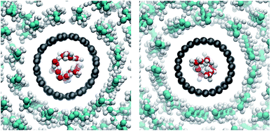
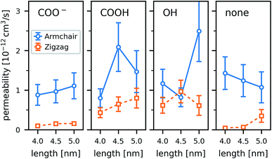
Water in nanopores is strongly confined. In our simulations, the water inside the CNTs adopted cylindrical shapes (Fig. 10), which are more pronounced in the wider armchair CNTs. The radius of the volume accessible for the water (carbon coordinates minus van der Waals radius of a carbon atom) is 3.8 Å in our armchair CNTs and 3.0 Å in our zigzag CNTs.The functional groups attached to the rim can significantly change the permeability of a CNT porin (Fig. 11). Whereas for the wider armchair CNTs in this work the permeability varies considerably, a clear trend is visible for the narrower zigzag CNTs. The polar hydroxyl (OH) and carboxyl (COOH) groups clearly enhance permeability compared to an unfunctionalized CNT. They prevent tilting and blockage of the pore by lipid headgroups, as discussed in the previous sections. The negatively charged COO− groups have the same effects structurally, but still reduce water permeability. They attract cations (here Na+) that reside at the pore entrance and partially block it. In the smaller CNTs (here those with a zigzag configuration), this leads to an almost complete blockage of the pore. These results show that, especially for small radii, rim functionalization is an important factor determining the permeability.
3.6 Carbon nanotube pairs and quartets
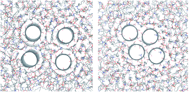
In atomistic simulations of more than one nanotube, lipids formed strong layers around the tubes for CNT pairs as well as quartets. Order is especially strong between two CNTs (Fig. 12). The lipid acyl chains stretch out and adapt to their squeezed-in position. This results in structures that are quite stable at least on the time scales of our simulations.The resulting configuration of CNTs in each simulation strongly depends on the starting conditions (see the ESI† for more details). CNT pairs that were prepared in direct carbon–carbon contact stayed in contact and pairs prepared with a distance of 2 nm between the central axes of the CNTs remained separated by one layer of lipid. Quartets of CNTs that were initially prepared in a square configuration with 2.5 nm distance remained separate. Quartet bundles initially prepared in contact quickly turned towards a stable rhombic shape (Fig. 13, right). This represents the hexagonal lattice structure expected on large scales due to the cylindrical shape.8
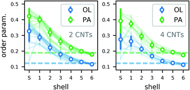
The lipid order parameter in all structures with more than one CNT (Fig. 14) shows the same behavior as for single CNTs. In our analysis, we distinguished shared (S) lipids that belong to the first shell of two CNTs and are therefore in a particularly confined configuration. For them, the order parameter varied more strongly due to the lower number of samples and depending on the exact position in which the lipid got trapped. However, the trend over all simulations shows a slight increase in order. Overall, we expect a lipid membrane densely packed with CNTs to be more ordered and maybe to undergo a phase transition to a gel phase.
4 Conclusions
We performed atomistic simulations of single CNT porins with different lengths, functionalizations and chiralities, and of CNT pairs and quartets. We also performed simulations of membrane embedded CNTs using a coarse-grained MARTINI-compatible model. In both atomistic and coarse-grained models, we observed pronounced annular lipid shells around the CNTs. The influences of functionalization and CNT chirality on the shell are negligible. The strong structuring of the lipids is therefore a universal feature for CNT porins.We observed in our simulations that the position and stability of the porin within the lipid bilayer depended on its length and the hydrophobicity of the functional groups at the rim. We found in atomistic and in coarse-grained simulations that CNTs minimize water exposure of their hydrophobic surface. In recent experiments,5 CNTs were observed without significant tilt. The mechanism behind this stability is still unclear. The tendency to tilt might be counterbalanced by external factors that minimize the exposure of the hydrophobic CNT surface, such as coating lipids or detergents, or by mechanical effects not captured in our simulation setup.
To control the openings of a CNT porin, different kinds of polar rim functionalizations can be used. Polar groups help prevent the blocking of short porins by lipid head groups, keep the pore open, and thus increase the efficiency of CNT-mediated transport across the membrane. Charged groups, however, attract ions that can block narrow pores and lower the water permeability. As a consequence, polar end functionalization affects the embedding structure and permeability of lipid-membrane embedded nanopores and in turn modulates the transport properties, e.g., by making the pore selective.21
The formation of CNT bundles within the membrane or the pairing of CNT porins result in stable membrane-spanning configurations with pores open to the solvent. Packing of CNTs into lattice structures stabilizes their vertical orientation. The lipid layering effect around these axially aligned CNTs is at least as strong as around isolated porins, and it might even have a stabilizing and structuring effect on the assemblies. We thus expect a large concentration of CNT porins to increase the permeability per CNT. However, such CNT bundles or more extended arrays will alter the mechanical properties of the membrane.
In conclusion, we demonstrated that CNT porins exert a strong influence on the surrounding membrane lipids. General principles emerge that artificial water channels made from CNT porins should fulfill, providing guidance for further experiments.
Conflicts of interest
There are no conflicts to declare.Acknowledgements
We thank Daniel Rhinow, Ramachandra Bhaskara, Roberto Covino, Lukas Stelzl, and Max Linke for helpful discussions. We acknowledge PRACE for access to Mare Nostrum at the Barcelona Supercomputing Centre, where we performed the box-size study. We ran all other simulations at the Max Planck Computing and Data Facility. This work was supported by the Max Planck Society. Open Access funding provided by the Max Planck Society.References
- G. Hummer, J. C. Rasaiah and J. P. Noworyta, Nature, 2001, 414, 188–190 CrossRef PubMed.
- M. Majumder, N. Chopra, R. Andrews and B. J. Hinds, Nature, 2005, 438, 930 CrossRef.
- J. K. Holt, H. G. Park, Y. Wang, M. Stadermann, A. B. Artyukhin, C. P. Grigoropoulos, A. Noy and O. Bakajin, Science, 2006, 312, 1034–1037 CrossRef PubMed.
- K. Kim, J. Geng, R. Tunuguntla, L. R. Comolli, C. P. Grigoropoulos, C. M. Ajo-Franklin and A. Noy, Nano Lett., 2014, 14, 7051–7056 CrossRef PubMed.
- J. Geng, K. Kim, J. Zhang, A. Escalada, R. Tunuguntla, L. R. Comolli, F. I. Allen, A. V. Shnyrova, K. R. Cho, D. Munoz, Y. M. Wang, C. P. Grigoropoulos, C. M. Ajo-Franklin, V. A. Frolov and A. Noy, Nature, 2014, 514, 612–615 CrossRef PubMed.
- A. Noy, G. Jia, Z. Jianfei and V. Frolov, Nanotube Trans-Membrane Channels Mimicking Biological Porins, US Pat., 20170304447A1, 2017, http://www.freepatentsonline.com/y2017/0304447.html.
- Y. Zhang, R. H. Tunuguntla, P.-o. Choi, A. Noy and A. Noy, Philos. Trans. R. Soc., B, 2017, 372, 20160226 CrossRef PubMed.
- A. Kalra, S. Garde and G. Hummer, Proc. Natl. Acad. Sci. U. S. A., 2003, 100, 10175–10180 CrossRef PubMed.
- B. J. Hinds, N. Chopra, T. Rantell, R. Andrews, V. Gavalas and L. G. Bachas, Science, 2004, 303, 62–65 CrossRef PubMed.
- J. Wu, K. Gerstandt, H. Zhang, J. Liu and B. J. Hinds, Nat. Nanotechnol., 2012, 7, 133–139 CrossRef PubMed.
- P. Boyer, H. Shams, S. L. Baker, M. R. K. Mofrad, M. F. Islam and K. N. Dahl, J. Mater. Chem. B, 2016, 4, 1324–1330 RSC.
- M. N. Al-Qattan, P. K. Deb and R. K. Tekade, Drug Discovery Today, 2017, 1–16 Search PubMed.
- M. Majumder, A. Stinchcomb and B. J. Hinds, Life Sci., 2010, 86, 563–568 CrossRef PubMed.
- B. Lee, Y. Baek, M. Lee, D. H. Jeong, H. H. Lee, J. Yoon and Y. H. Kim, Nat. Commun., 2015, 6, 7109 CrossRef PubMed.
- M. Thomas and B. Corry, Philos. Trans. R. Soc., A, 2015, 374, 1–20 Search PubMed.
- A. Noy, H. G. Park, F. Fornasiero, J. K. Holt, C. P. Grigoropoulos and O. Bakajin, Structure, 2007, 2, 22–29 Search PubMed.
- H. G. Park and Y. Jung, Chem. Soc. Rev., 2014, 43, 565–576 RSC.
- O. Beckstein, K. Tai and M. S. Sansom, J. Am. Chem. Soc., 2004, 126, 14694–14695 CrossRef PubMed.
- C. Peter and G. Hummer, Biophys. J., 2005, 89, 2222–2234 CrossRef PubMed.
- F. Fornasiero, H. G. Park, J. K. Holt, M. Stadermann, C. P. Grigoropoulos, A. Noy and O. Bakajin, Proc. Natl. Acad. Sci. U. S. A., 2008, 105, 17250–17255 CrossRef PubMed.
- F. Fornasiero, J. B. In, S. Kim, H. G. Park, Y. Wang, C. P. Grigoropoulos, A. Noy and O. Bakajin, Langmuir, 2010, 26, 14848–14853 CrossRef PubMed.
- C. Y. Lee, W. Choi, J. H. Han and M. S. Strano, Science, 2010, 329, 1320–1324 CrossRef PubMed.
- R. H. Tunuguntla, R. Y. Henley, Y. C. Yao, T. A. Pham, M. Wanunu and A. Noy, Science, 2017, 357, 792–796 CrossRef PubMed.
- C. Dellago, M. M. Naor and G. Hummer, Phys. Rev. Lett., 2003, 90, 4 CrossRef PubMed.
- C. Dellago and G. Hummer, Phys. Rev. Lett., 2006, 97, 1–4 CrossRef PubMed.
- D. J. Mann and M. D. Halls, Phys. Rev. Lett., 2003, 90, 4 CrossRef PubMed.
- R. H. Tunuguntla, F. I. Allen, K. Kim, A. Belliveau and A. Noy, Nat. Nanotechnol., 2016, 1–12 Search PubMed.
- M. Whitby and N. Quirke, Nat. Nanotechnol., 2007, 2, 87–94 CrossRef PubMed.
- S. Joseph and N. R. Aluru, Nano Lett., 2008, 8, 452–458 CrossRef PubMed.
- E. Secchi, S. Marbach, A. Nigues, D. Stein, A. Siria and L. Bocquet, Nature, 2016, 537, 210–213 CrossRef PubMed.
- R. García-Fandiño and M. S. P. Sansom, Proc. Natl. Acad. Sci. U. S. A., 2012, 109, 6939–6944 CrossRef PubMed.
- C. F. Lopez, S. O. Nielsen, P. B. Moore and M. L. Klein, Proc. Natl. Acad. Sci. U. S. A., 2004, 101, 4431–4434 CrossRef PubMed.
- X. Shi, Y. Kong and H. Gao, Acta Mech. Sin., 2008, 24, 161–169 CrossRef.
- E. J. Wallace and M. S. Sansom, Nano Lett., 2008, 8, 2751–2756 CrossRef PubMed.
- M. Dutt, O. Kuksenok, S. R. Little and A. C. Balazs, Nanoscale, 2011, 3, 240–250 RSC.
- M. Dutt, M. J. Nayhouse, O. Kuksenok, S. R. Little and A. C. Balazs, Curr. Nanosci., 2011, 7, 699–715 CrossRef.
- V. K. Gangupomu and F. M. Capaldi, J. Nanomater., 2011, 2011, 1–6 CrossRef.
- S. Höfinger, M. Melle-Franco, T. Gallo, A. Cantelli, M. Calvaresi, J. A. N. F. Gomes and F. Zerbetto, Biomaterials, 2011, 32, 7079–7085 CrossRef PubMed.
- A. A. Skandani, R. Zeineldin and M. Al-Haik, Langmuir, 2012, 28, 7872–7879 CrossRef PubMed.
- S. Kraszewski, A. Bianco, M. Tarek and C. Ramseyer, PLoS One, 2012, 7, 1–11 CrossRef PubMed.
- S. Z. Mousavi, S. Amjad-Iranagh, Y. Nademi and H. Modarress, J. Membr. Biol., 2013, 246, 697–704 CrossRef PubMed.
- P. Raczyński, K. Górny, M. Pabiszczak and Z. Gburski, Comput. Mater. Sci., 2013, 70, 13–18 CrossRef.
- W. F. Chan, H. Y. Chen, A. Surapathi, M. G. Taylor, X. H. Shao, E. Marand and J. K. Johnson, ACS Nano, 2013, 7, 5308–5319 CrossRef PubMed.
- E. Sarukhanyan, A. De Nicola, D. Roccatano, T. Kawakatsu and G. Milano, Chem. Phys. Lett., 2014, 595–596, 156–166 CrossRef.
- S. Tabari, Y. Jamali and R. Poursalehi, Procedia Mater. Sci., 2015, 11, 423–427 CrossRef.
- S. Joseph, R. J. Mashl, E. Jakobsson and N. R. Aluru, Nano Lett., 2003, 3, 1399–1403 CrossRef.
- Z. E. Hughes, C. J. Shearer, J. Shapter and J. D. Gale, J. Phys. Chem. C, 2012, 116, 24943–24953 CrossRef.
- E. J. Wallace and M. S. P. Sansom, Nanotechnology, 2009, 20, 045101 CrossRef PubMed.
- M. Dutt, O. Kuksenok, M. J. Nayhouse, S. R. Little and A. C. Balazs, ACS Nano, 2011, 5, 4769–4782 CrossRef PubMed.
- R. M. Bhaskara, S. M. Linker, M. Vögele, J. Köfinger and G. Hummer, ACS Nano, 2017, 11, 1273–1280 CrossRef PubMed.
- R. Parthasarathi, N. R. Tummala and A. Striolo, J. Phys. Chem. B, 2012, 116, 12769–12782 CrossRef PubMed.
- M. Lelimousin and M. S. P. Sansom, Small, 2013, 9, 3639–3646 CrossRef PubMed.
- S. Baoukina, L. Monticelli and D. P. Tieleman, J. Phys. Chem. B, 2013, 117, 12113–12123 CrossRef PubMed.
- R. Garcia-Fandiño, Á. Piñeiro, J. L. Trick and M. S. P. Sansom, ACS Nano, 2016, 10, 3693–3701 CrossRef PubMed.
- C. J. Dickson, B. D. Madej, Å. A. Skjevik, R. M. Betz, K. Teigen, I. R. Gould and R. C. Walker, J. Chem. Theory Comput., 2014, 10, 865–879 CrossRef PubMed.
- D. Case, V. Babin, J. Berryman, R. Betz, Q. Cai, D. Cerutti, I. T. E. Cheatham, T. Darden, R. E. Duke, H. Gohlke, A. Goetz, S. Gusarov, N. Homeyer, P. Janowski, J. Kaus, I. Kolossváry, A. Kovalenko, T. Lee, S. LeGrand, T. Luchko, R. Luo, B. Madej, K. Merz, F. Paesani, D. Roe, A. Roitberg, C. Sagui, R. Salomon-Ferrer, G. Seabra, C. Simmerling, W. Smith, J. Swails, R. Walker, J. Wang, R. Wolf, X. Wu and P. Kollman, AMBER 14, 2014 Search PubMed.
- J. Wang, R. M. Wolf, J. W. Caldwell, P. A. Kollman and D. A. Case, J. Comput. Chem., 2004, 25, 1157–1174 CrossRef PubMed.
- J. Wang, W. Wang, P. A. Kollman and D. A. Case, J. Comput. Chem., 2004, 25, 1157–1174 CrossRef PubMed.
- A. W. Sousa da Silva and W. F. Vranken, BMC Res. Notes, 2012, 5, 367 CrossRef PubMed.
- C. J. Dickson, L. Rosso, R. M. Betz, R. C. Walker and I. R. Gould, Soft Matter, 2012, 8, 9617 RSC.
- E. L. Wu, X. Cheng, S. Jo, H. Rui, K. C. Song, E. M. Dávila-Contreras, Y. Qi, J. Lee, V. Monje-Galvan, R. M. Venable, J. B. Klauda and W. Im, J. Comput. Chem., 2014, 35, 1997–2004 CrossRef PubMed.
- S. Jo, J. B. Lim, J. B. Klauda and W. Im, Biophys. J., 2009, 97, 50–58 CrossRef PubMed.
- S. Jo, T. Kim and W. Im, PLoS One, 2007, 2, 1–9 CrossRef PubMed.
- S. Jo, T. Kim, V. G. Iyer and W. Im, J. Comput. Chem., 2008, 29, 1859–1865 CrossRef PubMed.
- A. Minoia, BuildCstruct, 2011, http://chembytes.wikidot.com/buildcstruct Search PubMed.
- A. Minoia, L. Chen, D. Beljonne and R. Lazzaroni, Polymer, 2012, 53, 5480–5490 CrossRef.
- C. I. Bayly, P. Cieplak, W. D. Cornell and P. A. Kollman, J. Phys. Chem., 1993, 97, 10269–10280 CrossRef.
- D. Lu, Y. Li, U. Ravaioli and K. Schulten, J. Phys. Chem. B, 2005, 109, 11461–11467 CrossRef PubMed.
- B. Hess, C. Kutzner, D. Van Der Spoel and E. Lindahl, J. Chem. Theory Comput., 2008, 4, 435–447 CrossRef PubMed.
- T. A. Wassenaar, H. I. Ingólfsson, R. A. Böckmann, D. P. Tieleman and S. J. Marrink, J. Chem. Theory Comput., 2015, 11, 2144–2155 CrossRef PubMed.
- S. J. Marrink, H. J. Risselada, S. Yefimov, D. P. Tieleman and A. H. D. Vries, J. Phys. Chem. B, 2007, 111, 7812–7824 CrossRef PubMed.
- M. Vögele and G. Hummer, J. Phys. Chem. B, 2016, 120, 8722–8732 CrossRef PubMed.
- L. Monticelli, J. Chem. Theory Comput., 2012, 8, 1370–1378 CrossRef PubMed.
- N. Michaud-Agrawal, E. J. Denning, T. B. Woolf and O. Beckstein, J. Comput. Chem., 2011, 32, 2319–2327 CrossRef PubMed.
- R. J. Gowers, M. Linke, J. Barnoud, T. J. E. Reddy, M. N. Melo, S. L. Seyler, J. Domański, D. L. Dotson, S. Buchoux, I. M. Kenney and O. Beckstein, Proc. 15th Python Sci. Conf., 2016, pp. 98–105 Search PubMed.
- F. Zhu, E. Tajkhorshid and K. Schulten, Phys. Rev. Lett., 2004, 93, 224501 CrossRef PubMed.
- A. Berezhkovskii and G. Hummer, Phys. Rev. Lett., 2002, 89, 064503 CrossRef PubMed.
- F.-X. Contreras, A. M. Ernst and F. Wieland, Cold Spring Harbor Perspect. Biol., 2011, 3, 1–19 Search PubMed.
- A. G. Lee, Biochim. Biophys. Acta, Biomembr., 2004, 1666, 62–87 CrossRef PubMed.
- S. Katira, K. K. Mandadapu, S. Vaikuntanathan, B. Smit and D. Chandler, eLife, 2016, 5, 1–19 CrossRef PubMed.
Footnote |
| † Electronic supplementary information (ESI) available. See DOI: 10.1039/c8fd00011e |
| This journal is © The Royal Society of Chemistry 2018 |

