 Open Access Article
 This Open Access Article is licensed under a
 Creative Commons Attribution 3.0 Unported Licence
Structural behaviour of copper chloride catalysts during the chlorination of CO to phosgene†
Shaoliang
Guan
 ab,
Philip R.
Davies
a,
Emma K.
Gibson
ce,
David
Lennon
*b,
Giovanni E.
Rossi
b,
John M.
Winfield
b,
June
Callison
c,
Peter P.
Wells
cdf and
David J.
Willock
*a
ab,
Philip R.
Davies
a,
Emma K.
Gibson
ce,
David
Lennon
*b,
Giovanni E.
Rossi
b,
John M.
Winfield
b,
June
Callison
c,
Peter P.
Wells
cdf and
David J.
Willock
*a
aCardiff Catalysis Institute, School of Chemistry, Cardiff University, Cardiff, CF10 3AT, UK. E-mail: willockdj@Cardiff.ac.uk
bSchool of Chemistry, University of Glasgow, Joseph Black Building, University Avenue, Glasgow, G12 8QQ, UK. E-mail: david.lennon@glasgow.ac.uk
cUK Catalysis Hub, RCaH, Rutherford Appleton Laboratory, Didcot, OX11 0FA, UK
dDiamond Light Source Ltd., Diamond House, Harwell Science and Innovation Campus, Didcot, Oxfordshire OX11 0DE, UK
eDepartment of Chemistry, University College London, Gordon Street, London, WC1H 0AJ, UK
fSchool of Chemistry, University of Southampton, Southampton, SO17 1BJ, UK
First published on 20th February 2018
Abstract
The interaction of CO with an attapulgite-supported Cu(II)Cl2 catalyst has been examined in a micro-reactor arrangement. CO exposure to the dried, as-received catalyst at elevated temperatures leads to the formation of CO2 as the only identifiable product. However, phosgene production can be induced by using a catalyst pre-treatment where the supported Cu(II)Cl2 sample is exposed to a diluted stream of chlorine. Subsequent CO exposure at ∼370 °C then leads to phosgene production. In order to investigate the origins of this atypical set of reaction characteristics, a series of X-ray absorption experiments were performed that were supplemented by DFT calculations. XANES measurements establish that at the elevated temperatures connected with phosgene formation, the catalyst is comprised of Cu+ and a small amount of Cu2+. Moreover, the data show that unique to the chlorine pre-treated sample, CO exposure at elevated temperature results in a short-lived oxidation of the copper. On the basis of calculated CO adsorption energies, DFT calculations indicate that a mixed Cu+/Cu2+ catalyst is required to support CO chemisorption.
Introduction
There is a rapidly increasing demand for polyurethanes as lightweight, robust and transparent components in manufacturing. These polymers are prepared from isocyanates with methylene diphenyl diisocyanate being a representative material. Methylene diphenyl diisocyanate is itself prepared through the phosgenation of 4,4′-methylenedianiline, for which the total global production capacity in 2010 was estimated to be 5 million tonnes.1 Consequently, there is a high global demand for phosgene. Typically, phosgene production is undertaken alongside isocyanate production facilities as part of an integrated chemical complex. Chlorine, as a component of phosgene, is a major feedstock in the process but no chlorine is incorporated into the isocyanate product; it all ends up as HCl which represents a significant burden to the manufacturer and the environment.1 Cavani has previously considered routes by which the chlorine cycle in certain chemical industry operations could be made more efficient by means of the direct use of HCl as a co-reactant in oxychlorination reactions.2 More specifically, Zhang and co-workers have described how the oxychlorination of carbon monoxide may be exploited to produce phosgene.3–5 In order to effect sufficient separation of reagents/products, Zhang et al. propose a three stage process in which the first stage involves the chlorination of CO to produce phosgene over a supported copper(II) chloride catalyst whilst simultaneously reducing the catalyst to copper(I) chloride (Cu(I)Cl).Despite the potential of an oxychlorination process cycle capable of producing phosgene whilst consuming the HCl by-product of isocyanate manufacturing, there is a paucity of data on the surface chemistry of this process. This communication will examine aspects of the surface chemistry exclusively associated with the first stage of the oxychlorination cycle outlined by Zhang et al., namely the interaction between CO and a supported Cu(II)Cl2 catalyst. In an attempt to concentrate on durable materials, an industrial grade attapulgite supported Cu(II)Cl2 catalyst is examined. This catalyst has previously been investigated for the manufacture of trichloroethene and tetrachloroethene.6,7 (Attapulgite is the mineralogical name for palygorskite, a porous material formed from interspersed sheets of silica and sheets of octahedrally co-ordinated cations drawn from Mg2+, Al3+ and Fe3+.8,9)
Related materials such as Cu(II)Cl2/γ-Al2O3, which finds applications in the synthesis of the vinyl chloride monomer via the oxychlorination of ethene, have been studied using a range of techniques including UV/Vis, XANES and EXAFS.10,11 These studies have identified at least two distinct Cu species, at low loadings (<2%) Cu is found to be accommodated in surface sites on the alumina support with no Cl− in the first co-ordination sphere.12 These species show EPR signals with axial symmetry. The Cl− released from the CuCl2 appears as surface Al–Cl species. At higher loadings a second Cu species appears with Cu–Cl bonds present. This secondary species is found to be soluble in ethanol and the material loaded in this way leads to a more complex EPR spectrum. EXAFS measurements on the high loading samples show that Cu2+ is reduced in the presence of the ethene reagent.13 It was also suggested that KCl can act to stabilise Cu(II)Cl2, making the reduction processes more challenging and switching the rate determining step for dichloroethane production from Cu(I)Cl oxidation to Cu(II)Cl2 reduction by ethene.14
Respecting the theme of this Faraday Discussion meeting, this paper will concentrate on how a specific catalyst pre-treatment is able to facilitate favourable CO turnovers, in this case for the synthesis of phosgene. After a preliminary consideration of phosgene production in the presence of an as-received Cu(II)Cl2 catalyst and a Cu(II)Cl2 catalyst that has been pre-treated with dichlorine, the paper adopts a two-strand approach to address the detailed structural and oxidation state changes that occur as CO interacts with the supported Cu(II)Cl2 material. Firstly, a series of synchrotron X-ray absorption (XAS) experiments will be described that provide information on oxidation states and structure. Secondly, and on the basis of the XAS measurements, a series of DFT calculations are presented that explore possible structural motifs and energetics of the interaction between CO and Cu(II)Cl2. A follow-up paper will describe the reaction chemistry involved in this complex, but technically relevant, reaction system more comprehensively.15 The relevance of the catalyst pre-treatment stage to phosgene production is described in the results and discussion section.
Previous work using DFT to study the surface chemistry of related structures has employed the DFT+U approach to account for the strongly correlated nature of electrons at cationic Cu centres. For example, Lebernegg et al.16 have considered magnetic coupling between Cu2+ centres in copper halides, CuX2 structures (X = F, Cl, Br), which all form edge sharing linear chains of square planar complexes as described for Cu(II)Cl2 in the experimental section below. In the calculations presented here we also use a DFT+U approach and include the effect of the U parameter on the calculated properties of interest for catalysis.
Experimental
Chemicals and materials
CuCl2 (Sigma-Aldrich, 97%), CuCl2·H2O (Sigma-Aldrich, 99.99%), CuO (Acros Organics, 97%) and Cu4(OH)6Cl2 (Supelco, ≤100%) were used as received. The catalyst supplied by Ineos Chlor Ltd. contains 10% CuCl2 and 8% KCl supported on an attapulgite clay and is described elsewhere.6,7 Before use the material was dried under a continuous stream of N2 (BOC, 99.998%) at a flowrate of 50 mL min−1 and a temperature of 110 °C for 12 h. Chlorine pre-treated catalyst samples were prepared by exposing the dried catalyst to a Cl2/N2 co-feed (6 mL min−1 Cl2, 50 mL min−1 N2) for 10 min at 370 °C. This chlorine exposure was repeated a further three times before reverting the carrier gas back to pure N2. The sample was maintained at 370 °C for 30 minutes, after which the heating was turned off and the sample allowed to cool to ambient temperature in the presence of flowing nitrogen. For the XAS measurements, the dried and chlorine pre-treated copper chloride catalyst samples were isolated in a nitrogen atmosphere for transportation to the synchrotron.Reaction testing was performed using a micro-reactor facility located at the University of Glasgow. A detailed description of that apparatus will appear in a subsequent publication.15 Briefly, a combination of in-line UV-visible spectroscopy and infrared spectroscopy was used to monitor the gas phase exiting the reactor.
Catalyst testing
Reactions were carried out using a flow reactor charged with varying amounts of catalyst (∼0.500 g). A by-pass reactor positioned alongside the principal reactor within the furnace was loaded with a comparable mass of ground quartz. All experiments were carried out with an overall flow rate of 159 sccm (standard cubic centimetre per minute, cm3 min−1) in order to keep the contact time the same for all experiments. All gas flows were controlled by using mass flow controllers (Hastings GFC-202, 0–100 sccm). In order to avoid corrosion, an N2 purge system was connected to the mass flow controllers to ensure the lines were purged when not in use.Reagent gases were mixed in a mixing vessel with Ballotini balls to ensure dispersion of the gases, followed by an in-line filter to retain catalyst particles in the reactor. The reaction temperature was monitored using a thermocouple (HANNA HI 93532) with a probe in the sleeve of the reactor loaded with the catalyst. Post-reactor, an N2-drive line feeds into the flow before a second in-line filter; this arrangement ensures that all reagents remain in the gaseous phase. A three-way valve allows the reactor exit flow to be directed either to the IR and UV-Vis spectrophotometers or directly through a chemical scrubber to the vent. The scrubber was filled with an aqueous solution of NaOH that ensured the chlorinated products were neutralised before exiting via the vent.
XAFS
Copper K-edge XAFS studies of the catalyst materials and a series of reference standards were carried out on the B18 beamline at the Diamond Light Source, Didcot, UK. Measurements were performed using a quick extended (QE) XAFS set-up with a fast-scanning silicon (111) double-crystal monochromator. The time resolution of the spectra reported herein was 49 seconds per spectrum (kmax = 14), and on average three scans were acquired to improve the signal-to-noise ratio of the data. All ex situ samples were diluted with cellulose to optimize the effective-edge step of the XAFS data and measured in transmission mode using ion-chamber detectors. Reference samples were CuO, CuCl2, CuCl2·H2O, and Cu4(OH)6Cl2. A reference spectrum of anhydrous CuCl2 was prepared in situ by heating CuCl2 (Sigma Aldrich 99.995%, with boron nitride) in a 3 mm O.D. quartz capillary under flowing helium. After reaching 100 °C the XANES spectra resembled that reported earlier by Ferrandon et al.17 All transmission XAFS spectra were acquired concurrently with the copper reference foil placed between It and Iref XAS data processing, and EXAFS analysis were performed using IFEFFIT18 with the Horae package19 (Athena and Artemis).In situ XAFS measurements were performed in transmission mode using a fixed-bed quartz microreactor (O.D. 5.6 mm, length 200 mm, Hilgenberg), with a gas flow setup similar to that described by Matla et al.20 Due to the high loading of Cu in the catalyst the samples were mixed with boron nitride to achieve an optimal absorption in the XAFS spectra. The temperature was controlled using a Eurotherm controller with a type K thermocouple positioned in the centre of the heater block. The reactor was heated to 370 °C at a ramp rate of 10 °C min−1 under a flow of He (50 mL min−1, 99.99% BIP, BOC). The reactor was then held at this temperature for 30 min under a flow of CO in He (50 mL min−1, 10% CO in He). Finally, the reactor was cooled down to room temperature under He.
Density functional theory
All calculations were carried out using the VASP package21 with the PBE functional.22 Core states for all atoms were represented using the projector augmented wave (PAW) method.23 The PAW potentials for Cu and Cl left 11 and 7 electrons in the valence states for the respective neutral atoms, while all other atoms have their expected number of valence electrons.The crystal structure of Cu(II)Cl2 is shown in Fig. S1.† The material has a layered structure with Cu2+ cations in rows of edge sharing square planar structures aligned with the b-axis of the unit cell. Neighbouring Cu2+ ions are bridged by two co-ordinated Cl− anions. The rows are arranged to give each Cu2+ ion an additional two axial Cl− ligands in neighbouring chains. This leads to an experimental crystal structure for anhydrous Cu(II)Cl2 in which each Cu2+ cation has 4 short Cu–Cl (2.35 Å) and 2 long Cu–Cl distances (2.9 Å), so that the Cu2+(d9) centres can be thought of as having a strongly Jahn–Teller distorted environment. Besides this weak axial co-ordination between Cu2+ and Cl−, inter-row and inter-layer spacing is dependent on dispersion interactions and so all calculations included a parameterised representation of the dispersion interaction using the Grimme D2 approach.24 We use reciprocal space (k-point) sampling following the Monkhorst–Pack scheme.25 Convergence of the bulk energy for Cu(II)Cl2 with respect to planewave cutoff and k-point sampling was tested (Fig. S2†) resulting in a planewave cutoff of 500 eV and k-point sampling of 5 × 5 × 5 for the bulk unit cell. For density of states (DOS) calculations the density of the k-point sampling was increased to 7 × 7 × 7. The k-point sampling was adjusted for the larger unit cells used to represent surfaces to 3 × 3 × 1 with only 1 k-point used in the direction perpendicular to the surfaces of slab models. A check of the calculated surface defect energy using 5 × 5 × 1 k-point sampling showed a variation of only 0.003 eV. A dipole correction perpendicular to the surface plane was used for all slab calculations.
In addition, as discussed in the introduction section, the strong correlation effects for electrons located at the Cu sites require the application of the DFT+U approach.26 From analysis of the calculated electronic structure Lebernegg et al.16 suggested that Cu(II)Cl2 can be described using a Hubbard model with Ueff = 4.0. However, they also point out that differences in local basis set and planewave approaches require higher U values when calculations are carried out with VASP. More extensive computational literature is available for Cu2+ and Cu+ in oxide materials, due to the promising combination of transparency and electrical conductivity for Cu+ containing oxides. Scanlon et al.27 have considered p-type defects in Cu2O with the PBE functional and found that a U value of 5.2 best reproduced the valence band features expected from X-ray photoelectron spectroscopy. However, they also concluded that the DFT+U approach cannot reproduce the detailed electronic structure of polaronic defects in this material. Mishra et al.28 have applied DFT+U calculations to study the surface structure and adsorption of CO2 to both CuO and Cu2O. They employed a range of U values and identified U = 7 as giving the best match to the experimental band gap and ion magnetic moments for CuO. While the electronic structure of Cu2O was found to be more challenging, U = 7 was found to give a good account of the geometric structure of the material. In this work we have also looked at the effect of the U parameter on the calculated energetics through a comparison of results for values of U = 4 and U = 7, and this allows us to show the sensitivity of the calculated material properties to the choice of this parameter.
The d9 configuration of the Cu2+ centres leads to magnetic interactions between Cu centres which have previously been studied in some detail.16 We have tested the magnet ordering in the bulk unit cell. This unit cell contains two Cu2+ ions within each row and two rows of CuCl2 (Fig. S1†). We find that having parallel spins at adjacent Cu centres within a CuCl2 row is favoured by 0.01 eV per atom but the coupling between rows is much weaker with practically no difference between Cu atoms on adjacent rows having a ferromagnetic or anti-ferromagnetic alignment. The spin arrangement used in our calculations is illustrated in Fig. S3.†
For surface calculations we use a four layer slab model with the lowest layer of CuCl2 chains frozen at bulk positions to represent the constraint of the surface matching to a more extended crystal bulk.
The surface energy is calculated with the fixed lower layer taken into account using:29
 | (1) |
 | (2) |
The adsorption energy, Eads, of CO to the Cu sites of various slab models of the surface were calculated using:
| Eads = ECO+slab − Eslab − ECO | (3) |
Results and discussion
The FT-IR spectra of the products resulting from CO reacting with the as-received catalyst (Fig. 1a) indicated that, as well as the signal of unreacted C![[triple bond, length as m-dash]](https://www.rsc.org/images/entities/char_e002.gif) O observed at 2140 cm−1, there is a large peak at 2343 cm−1 due to the asymmetric C
O observed at 2140 cm−1, there is a large peak at 2343 cm−1 due to the asymmetric C![[double bond, length as m-dash]](https://www.rsc.org/images/entities/char_e001.gif) O stretching mode of CO2. The bending mode of OCO at 660 cm−1 can also be seen in the spectra. Importantly, no phosgene formation was observed for the as-received catalyst reacting with CO. A variety of sample conditioning steps were explored but no combination of heating pre-treatments was able to induce phosgene production on CO exposure from this industrial grade Cu(II)Cl2 oxychlorination catalyst. In contrast, a chemical pre-treatment using short exposures of diluted chlorine (see experimental section), was able to induce phosgene synthesis. Fig. 1b shows the infrared spectrum of the reactor output for CO exposure to a chlorine pre-treated catalyst maintained at 370 °C. In addition to the CO and CO2 bands evident in Fig. 1a, bands observed at 1825 and 845 cm−1 are due to the CO stretch and C–Cl asymmetric stretch in COCl2, respectively. Comparing the two spectra confirms the necessity of a Cl2 pre-treatment to the catalyst for phosgene production. Moreover, the attenuation of the CO2 band intensity for the chlorine pre-treated catalyst (Fig. 1b) compared to the as-received catalyst (Fig. 1a) suggests that the CO oxidation to produce CO2 and CO chlorination to produce COCl2 are competing reaction pathways. Importantly, phosgene production cannot be sustained on continued CO exposure. The time dependant characteristics of COCl2 and CO2 formation is beyond the scope of the present communication and will be more comprehensively examined in a subsequent publication.15
O stretching mode of CO2. The bending mode of OCO at 660 cm−1 can also be seen in the spectra. Importantly, no phosgene formation was observed for the as-received catalyst reacting with CO. A variety of sample conditioning steps were explored but no combination of heating pre-treatments was able to induce phosgene production on CO exposure from this industrial grade Cu(II)Cl2 oxychlorination catalyst. In contrast, a chemical pre-treatment using short exposures of diluted chlorine (see experimental section), was able to induce phosgene synthesis. Fig. 1b shows the infrared spectrum of the reactor output for CO exposure to a chlorine pre-treated catalyst maintained at 370 °C. In addition to the CO and CO2 bands evident in Fig. 1a, bands observed at 1825 and 845 cm−1 are due to the CO stretch and C–Cl asymmetric stretch in COCl2, respectively. Comparing the two spectra confirms the necessity of a Cl2 pre-treatment to the catalyst for phosgene production. Moreover, the attenuation of the CO2 band intensity for the chlorine pre-treated catalyst (Fig. 1b) compared to the as-received catalyst (Fig. 1a) suggests that the CO oxidation to produce CO2 and CO chlorination to produce COCl2 are competing reaction pathways. Importantly, phosgene production cannot be sustained on continued CO exposure. The time dependant characteristics of COCl2 and CO2 formation is beyond the scope of the present communication and will be more comprehensively examined in a subsequent publication.15
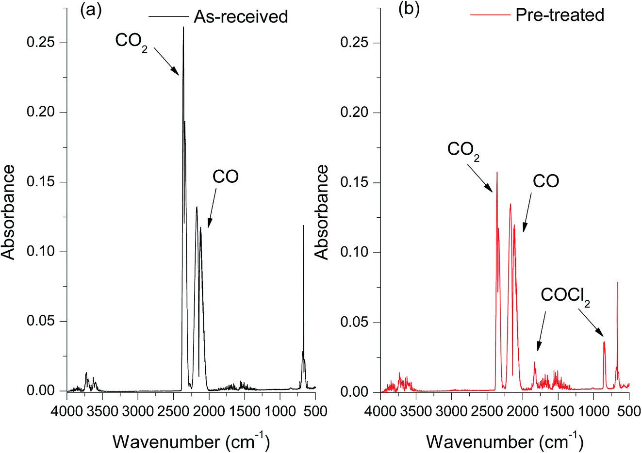 | ||
| Fig. 1 In-line FT-IR spectra of outlet gas mixture of CO reacting with the catalyst at 370 °C showing the effect of pre-treating the catalyst with Cl2(g). (a) As-received catalyst; (b) chlorine pre-treated catalyst. | ||
To investigate the differences between the as received and Cl2 pre-treated material in more detail we turned to XANES measurements. The Cu+ or Cu2+ oxidation states show a number of characteristic features in the XANES region of the Cu K-edge XAFS spectra and a series of reference materials were examined to support the analysis, Fig. 2 (left frame). All of the Cu2+ reference compounds show a weak pre-edge feature at 8977 eV, due to the 1s → 3d transition. This is forbidden for Cu+ species.30 Apart from the pre-edge feature, Kau et al.31 observed no other significant peaks below 8985 eV for any Cu2+ species. However, for Cu+ species, a sharp feature below the dashed line in Fig. 2 would be expected, around 8983 eV due to the 1s → 4p transition, this is evident in the spectra for the Cu2O materials shown in Fig. 2 (right frame).30
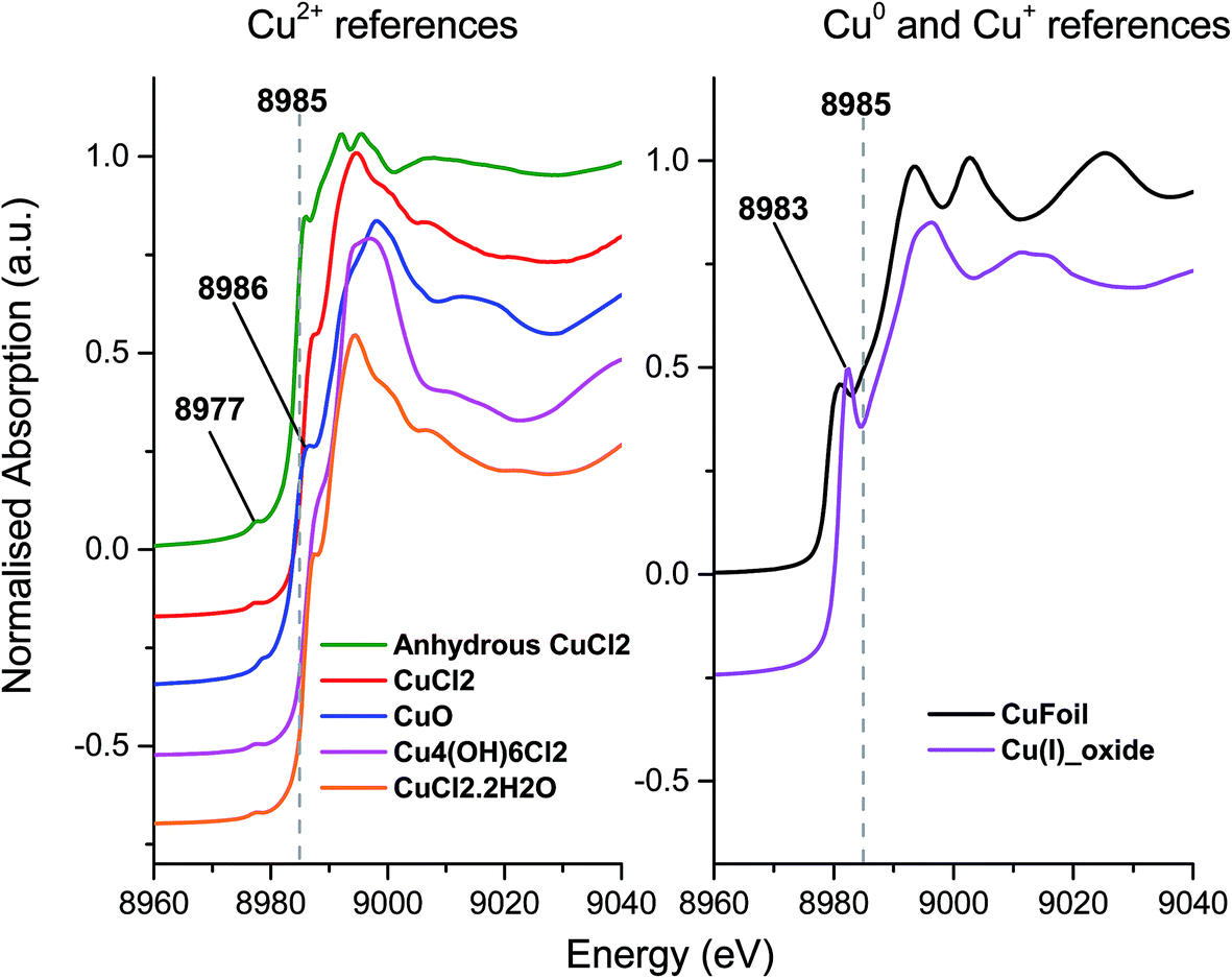 | ||
| Fig. 2 Ex situ XANES spectra – Left: Cu2+ reference compounds, and right: Cu+ reference compounds, spectra are vertically offset for clarity. | ||
The XANES spectra, shown in Fig. 3, of the as-received and Cl2 pre-treated catalysts are both consistent with Cu2+ species, exhibiting the characteristic features at 8986 eV and 8977 eV and without the strong feature at 8983 eV associated with Cu+. The chlorine pre-treated sample resembles that of anhydrous CuCl2, which may imply that the Cl2 pre-treatment has, to some extent, driven off adsorbed water or hydroxyl groups from the Cu(II)Cl2 catalyst.
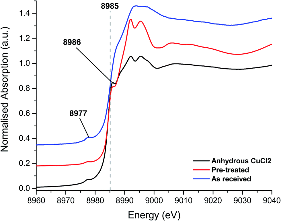 | ||
| Fig. 3 XANES spectra – fresh catalyst as received, chlorine pre-treated and the anhydrous CuCl2 (prepared in situ). | ||
On heating the chlorine pre-treated sample from RT to 200 °C the sample initially resembles anhydrous CuCl2, but by 300 °C, the 1s → 3d feature at 8977 eV and the feature at 8986 eV consistent with Cu2+ species loses intensity (Fig. 4). By 360 °C the edge has shifted to lower energy and a pronounced pre-edge feature at 8983 eV is observed, consistent with the presence of a Cu+ species. The small feature at 8978 eV is still present, (more easily observed in the 1st derivative spectrum, Fig. S4†). We therefore conclude that by the end of the temperature ramp at 367 °C, which corresponds to the temperature at which phosgene production is obtained (Fig. 1b), the sample consists of a mixture of Cu+ and a small amount of Cu2+. This reduction to Cu+ is also observed for the fresh catalyst.
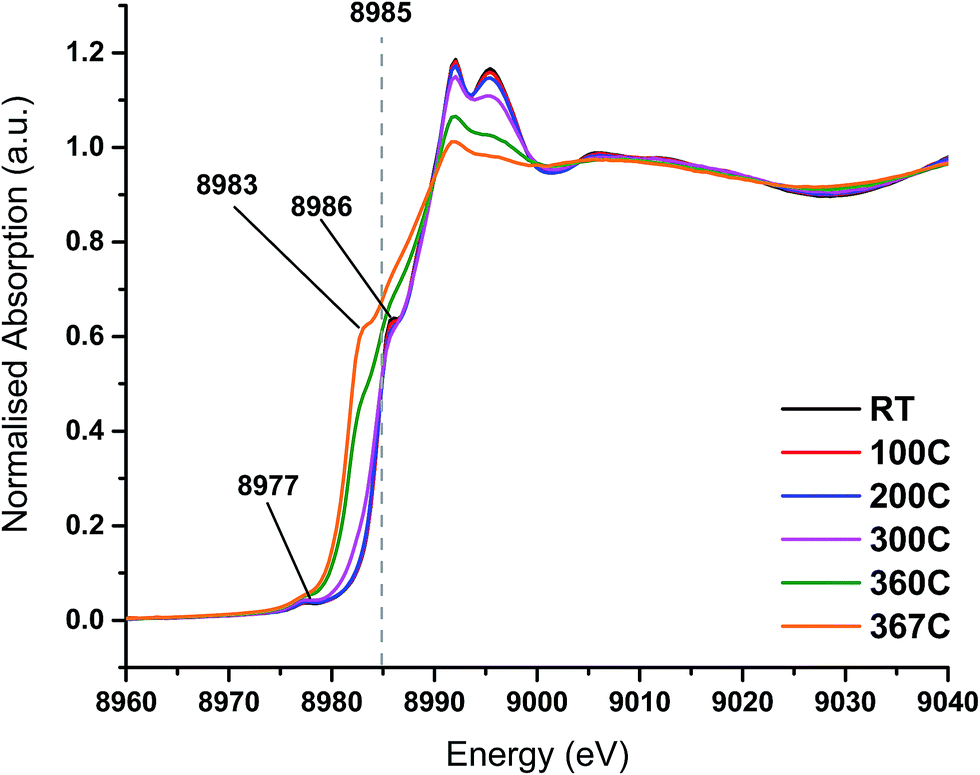 | ||
| Fig. 4 In situ XANES spectra – temperature ramp of chlorine pre-treated catalyst showing loss of anhydrous-like Cu2+ to Cu+ species. | ||
Fig. 5 shows that, after the heating ramp and exposure of the Cl2 pre-treated sample to CO (1 min), the characteristic Cu+ feature at 8983 eV significantly diminishes in intensity, the adsorption edge shifts to higher energy, and the first feature after the edge (at 8992 eV) increases. In addition, the small pre-edge feature of Cu2+ at 8977 eV increases, more easily observed in the insert of Fig. 5a. This pre-edge feature, unique to Cu2+ species, becomes visible on introduction of CO and then disappears almost completely after 10 min of exposure. Although CO is well known as a reducing agent, these changes point unambiguously to an oxidation of Cu+ to Cu2+ during the first minute of CO exposure. Interestingly, this re-oxidation is not observed for the fresh catalyst (Fig. 5b).
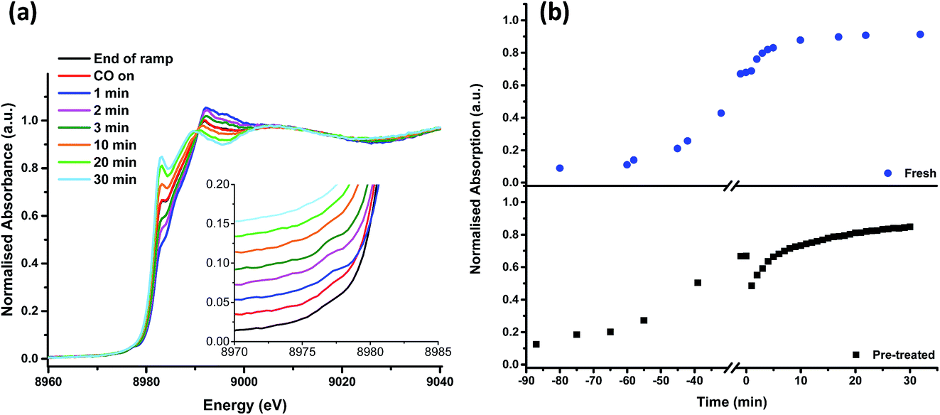 | ||
| Fig. 5 In situ XANES spectra – (a) from the end of the temperature ramp (367 °C, under helium) then on exposure to CO. The insert shows the pre-edge region around 8977 eV in more detail. (b) The time dependence of the pre-edge feature at 8983 eV, characteristic of Cu+ species during the ramp and on exposure to CO, (blue dots: fresh catalyst, black squares: Cl2 pre-treated catalyst). Negative time points represent the temperature ramp; time t = 0 indicates the time that the catalyst was exposed to CO (temperature = 367 °C). | ||
From 10 min to 30 min of CO exposure, the spectra resemble Cu+ species, with an increasing intensity of the feature at 8983 eV.
The observations on Cu oxidation state from this series of experiments is summarised in Scheme 1: for the Cl2 pre-treated catalyst, at the end of the ramp we have a mixture of Cu+ and Cu2+ then, on introduction of CO, re-oxidation occurs giving Cu2+, which is quickly reduced to Cu+ after 10 min exposure. The oxidation of Cu+ to Cu2+ on introduction of CO to the gas feed is difficult to justify. We speculate that excess chlorine adsorbed within the pore network of the Cl2 pre-treated material is released when CO is first introduced, and it is this Cl2 that oxidises Cu. Interestingly, this re-oxidation step is not observed for the fresh catalyst, which only produces CO2, whereas the pre-treated catalyst produces both CO2 and COCl2 (Fig. 1). Further work is required to better understand the origins of the oxidation process revealed in Fig. 5b.
 | ||
| Scheme 1 A representation of the copper oxidation states accessible to the chlorine pre-treated catalyst on (i) thermal ramping to 350° in a flowing stream of He, (ii) initial exposure to a flowing mixture of He + CO at 367 °C and (iii) extended exposure to a flowing mixture of He + CO at 367 °C. | ||
EXAFS
Analysis of the extended X-ray absorption fine structure (EXAFS) region was performed on the spectrum after 1 min of CO exposure Fig. 6, Table 1. This corresponds to the conditions under which a maximum in the rate of phosgene production is observed. The magnitude component of the k2 weighted Fourier transform of the data of the spectra recorded at 1 min of CO exposure, Fig. 6, hint that a low Z-number scatterer is present. This is similar to the work of Lamberti et al.32 who propose a mixture of copper aluminate and active CuCl2 in their CuCl2/Al2O3 catalyst. Our data fits well to Cu–O and Cu–Cl contributions at 1.84 ± 0.02 and 2.21 ± 0.01 Å, respectively, in Fig. 6 and Table 1. From the XANES spectrum after 1 min of CO exposure (Fig. 5a), we expect the Cu to exist in a distorted octahedral environment, however, the refined coordination numbers from the EXAFS analysis are lower than expected. There are two possibilities to explain this. Firstly, if a mixture of Cu species is present, the coordination number obtained from the fit would only be proportional to the contributions of each species.32 Secondly, destructive interference of the scattering paths from the axial and equatorial neighbours has previously been observed for distorted octahedral Cu species, resulting in only the equatorial contributions being observed, leading to difficulties in refining the coordination numbers.33 As EXAFS is an averaging technique, we cannot rule out that, in our case, we may also have a mixture of Cu2+ species present at this point in the reaction coordinate.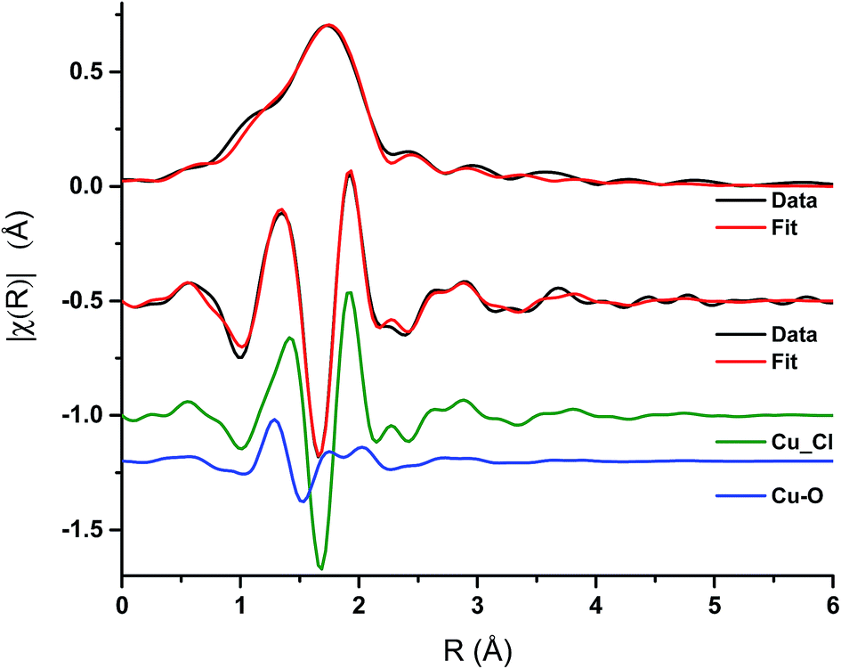 | ||
| Fig. 6 EXAFS spectra – magnitude component of the k2 weighted Fourier transform of the data and fit for the 1 min CO exposure spectrum, and the imaginary component of the paths used in the fit. | ||
| Samples | Abs − Sc | N | R/Å | 2σ2/Å2 | E 0/eV | R factor |
|---|---|---|---|---|---|---|
| 1 min CO | Cu–Cl (CuCl) | 1.65 ± 0.08 | 2.21 ± 0.01 | 0.007 | −2 ± 1 | 0.005 |
| Cu–O (CuCl2·2H2O) | 0.50 ± 0.08 | 1.84 ± 0.02 | 0.003 |
To complement these XAS measurements we have carried out electronic structure calculations on the copper chloride lattice in order to better understand the energetics and structural implications of Cl removal from the Cu(II)Cl2 lattice during heat treatment or reduction through reaction with CO. The next section covers this work and demonstrates the structural motifs that are induced on the chlorine pre-treated support that can, intermittently, support phosgene production.
DFT results
DFT calculations began with the optimisation of the bulk unit cell lattice parameters through relaxing the atom positions for a series of cell expansion/contraction values. The resulting plot of calculated energy vs. cell volume was fitted using the Murnaghan equation of state34 (Fig. S6†). The resulting bulk structure geometry gives in plane the expected CuCl2 row structures with in plane Cu–Cl distances of 2.285 Å and inter-layer axial Cu⋯Cl = 3.001 Å at the PBE+U (=7) with a D2 level of theory.The calculated density of states with each of the two U values is shown in Fig. S7.† In both cases the band gap is defined by the top of the valence band consisting of majority spin Cu2+ d-states and empty d-states of the minority spin. In the case of U = 4 the calculated band gap is small (0.3 eV) while for U = 7 a clear gap exists of around 0.9 eV. The choice of U parameter is made so that we can demonstrate the influence of U on the calculated energies comparing the lowest value for which a band gap is present to the most commonly used value for oxidised Cu in the literature.
In our XANES data we have seen changes in oxidation state for Cu when the Cl2 pre-treated samples are subjected to a heating ramp or when CO is introduced into the system. The reduction of Cu will take place as Cl is removed from the lattice and so we have calculated the defect energies, Edef, for the creation of an anion vacancy in the surface. The DFT calculations also give information on the structural changes that are caused by the removal of Cl. The defect energy is calculated as the energy change for the simple reaction:
| CumCl2m = CumCl2m−1 + 1/2Cl2 | (4) |
| Structure/simulation slab | E def (U = 4)/eV | E def (U = 7)/eV |
|---|---|---|
| Surface defect/Cu16Cl32 | 1.23 | 1.32 |
| 2nd layer defect/Cu16Cl32 | 1.32 | 1.41 |
| Surface defect/Cu32Cl64 | 1.19 | 1.25 |
| 2nd layer defect/Cu32Cl64 | 1.28 | 1.38 |
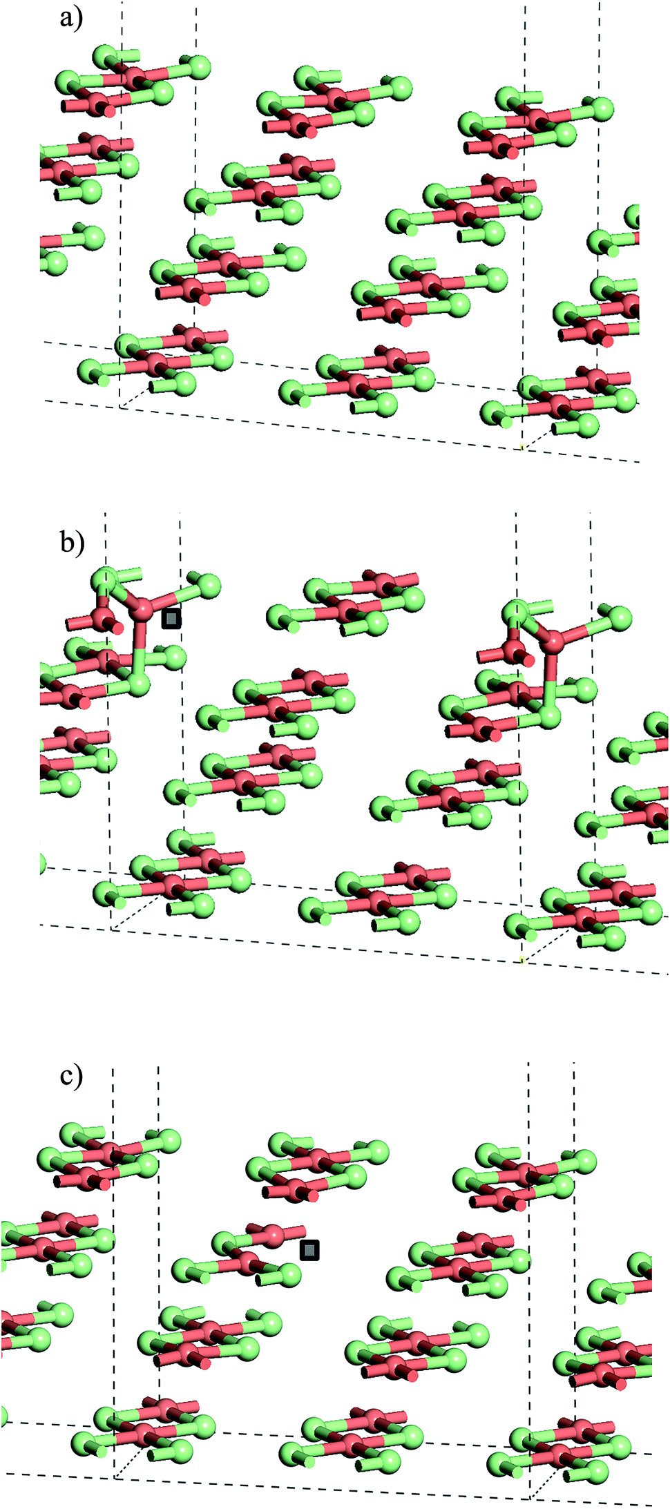 | ||
| Fig. 7 (a) Slab model of the stoichiometric CuCl2(010) surface. (b) Structure with Cl− vacancy in the surface layer of the slab and (c) structure with a Cl− vacancy in the second layer of the slab. Note that the position of the anion vacancy is indicated by a grey square in (b) and (c). All structures optimised with PBE+U using U = 7 and Grimme D2 dispersion included. Atoms coloured Cu: pink and Cl: green. | ||
From the stoichiometric surface, a defect was created through the removal of a single Cl− ion, to leave a vacancy, V, in the surface. The electron associated with this defect would be expected to reduce a single Cu2+(d9) cation to Cu+(d10) and so the initial spin state arrangement used for defect calculations was adjusted to have one Cu site neighbouring the defect assigned zero spin. As the CuCl4 units are edge sharing, this results in two surface Cu ions being bridged by a single Cl− anion. The relaxed structure (Fig. 6b) shows that the remaining Cl− ion in the –Cu–Cl–Cu–V– square has moved out of the plane of the CuCl2 chain with one Cu cation moving closer to a second layer Cl− (Cu⋯Cl (2nd layer) = 2.372 Å) giving it a pseudo-tetrahedral (4-fold) geometry and one Cu cation moving further from the second layer and adopting a pseudo-trigonal planar (3-fold) geometry (Cu⋯Cl (2nd layer) = 3.017 Å). Analysis of the final spin state shows that the 4-fold Cu has practically 0 spin while the 3-fold Cu has associated spin density. This suggests that the 4-fold Cu is formally a Cu+(d10) cation while the 3-fold remains a Cu2+(d9) cation. Within the defective chain, Cu–Cl distances are also affected, with shorter Cu–Cl to the single bridging Cl− ion than seen in the stoichiometric surface (Cu(4-fold)–Cl = 2.214 Å and Cu(3-fold)–Cl = 2.151 Å).
The calculated energy to form the surface defect in the Cu16Cl32 slab is 1.32 eV (U = 7, Table 2) increasing to 1.41 eV if a defect is created in the second layer of the same slab model (Fig. 6c). There is very little structural re-arrangement following relaxation of the second layer defect structure compared to that discussed above for the surface defect. Hence, the higher energy to create a sub-surface defect may result from the more constrained environment of the sub-surface Cl− sites.
Doubling the cell in the CuCl2 chain direction to give a Cu32Cl64 slab gives a calculated surface defect energy 5% lower than calculated for the smaller cell while the second layer defect has a calculated energy around 2% lower. In the chain direction the Cu16Cl32 cell has only two Cu sites while in the doubled cell there are four so that it should be expected, given the observed surface geometry changes, that there are defect–defect interactions present in the smaller slab. Indeed, for the surface defect model, using the larger cell, the movement of the Cl− anion in the –Cu–Cl–Cu–V– square is significantly smaller than seen for the Cu16Cl32 slab so that there is practically no difference in the geometries of the two Cu cations that this anion bridges (Fig. S8†). This comparison of the Cu16Cl32 and Cu32Cl64 slab models also suggests that at low anion defect concentrations the disruption of the lattice will be relatively minor while at high concentrations, where the Cu+ content contributes significantly to the XANES, we should also expect significant geometric changes around the Cu sites, particularly near to the surface of the Cu(II)Cl2 crystallites.
Table 2 also gives data for defect creation using the U = 4 Hubbard parameter which consistently gives lower calculated defect energies by between 0.06 and 0.10 eV depending on the position of the defect and the cell size employed. Even so the differences observed between different defect locations or slab sizes follow the same trend for either choice of U, suggesting that the properties of interest here are relatively insensitive to this parameter.
Table 3 gives the calculated energies and some geometric data for the adsorption of CO to the CuCl2(010) surface structures using the slab models for stoichiometric and defective surfaces and Fig. 8 shows the corresponding optimised geometries for the Cu16Cl32 slab based models. CO adsorbs weakly to the stoichiometric surface with a calculated adsorption energy of only −13 kJ mol−1 (U = 7) and a relatively long Cu⋯CO interaction distance (2.561 Å), although this is still shorter than the Cu⋯Cl distance for the inter-layer interactions in the bulk material. The CO bond length is also close to that for the free gas phase CO reference state (1.143 Å). On introduction of a surface defect the calculated CO adsorption energy becomes considerably more favourable (−55 kJ mol−1). As discussed above the surface defect in the Cu16Cl31 slab model is neighboured by one 4-fold and one 3-fold co-ordinated Cu centre and so we expected different behaviour for adsorption to each site. To test this two calculations were carried out and the results are compared in Table 3. The adsorption energies are actually the same irrespective of the choice of Cu site. Absorption of CO raises the Cu site out of the surface plane producing a 4-co-ordinate Cu centre in a pseudo-tetrahedral geometry in each case (Fig. 8b and c). The Cu–CO distance is considerably shorter and the CuC–O bond length longer than seen for the stoichiometric surface, consistent with the stronger interaction with the surface. Calculation of the spin density for either structure shows practically no spin density on the Cu centre to which CO co-ordinates suggesting that the electronic state is re-organised during optimisation to place the Cu+(d10) centre in the position bonding to CO (Fig. S9†) so that the surface responds to the adsorbate and re-arranges to the same structure irrespective of the initial geometry of the defect site. Although we see significant surface re-arrangement of the surface with the surface defect present the CO adsorption has a lower energy than seen for other surfaces. For example, calculations using a similar approach for CO on Fe(111) give adsorption energies of 119 kJ mol−1 and a CO bond length of 1.164 Å for CO at an Fe top site using a similar level of theory. 35
| Structure/simulation slab | E ads (U = 4)/kJ mol−1 | E ads (U = 7)/kJ mol−1 | Cu⋯COa/Å | CuC–Oa/Å |
|---|---|---|---|---|
| a Geometry taken from the U = 7 optimised structures. b Initial co-ordination of adsorption site in reference slab calculation. | ||||
| Stoichiometric (010)/Cu16Cl32 | −7 | −13 | 2.561 | 1.141 |
| Surf. def., Cu(4-fold)b site/Cu16Cl31 | −55 | −55 | 1.838 | 1.147 |
| Surf. def. Cu(3-fold)b site/Cu16Cl31 | −55 | −55 | 1.840 | 1.147 |
| 2nd layer defect/Cu16Cl31 | −13 | −16 | 2.432 | 1.141 |
| Stoichiometric (010)/Cu32Cl64 | −11 | −12 | 2.614 | 1.141 |
| Surf. def./Cu32Cl63 | −39 | −32 | 1.851 | 1.146 |
| 2nd layer defect/Cu32Cl63 | −13 | −15 | 2.417 | 1.140 |
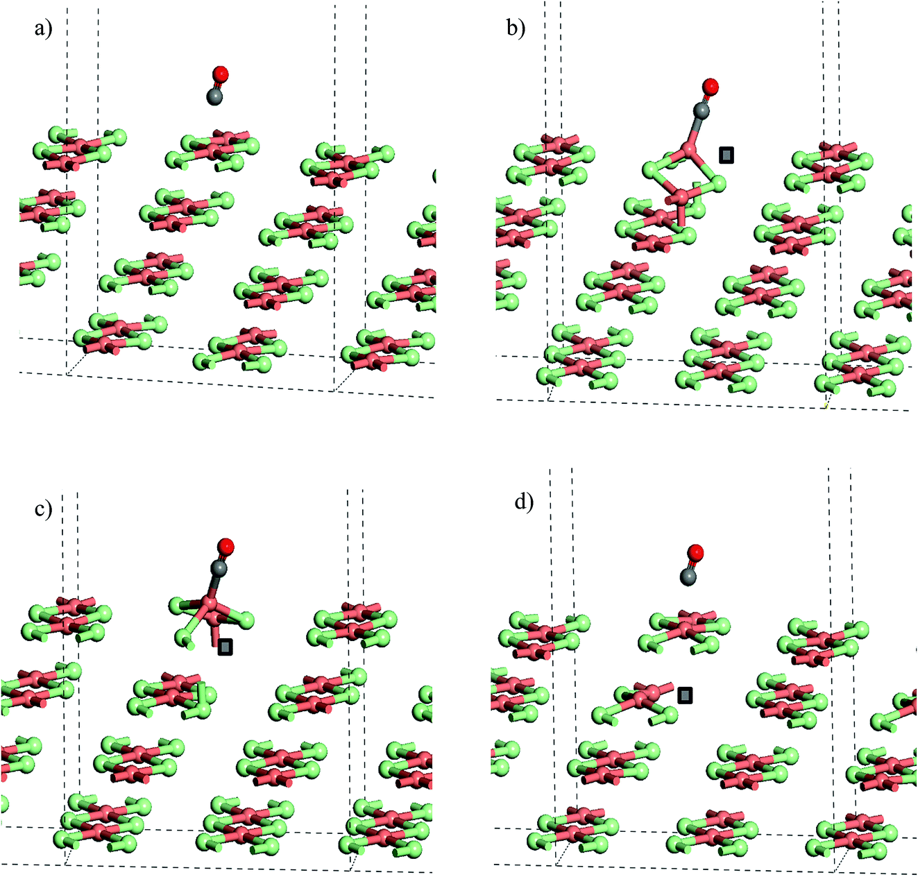 | ||
| Fig. 8 Calculated CO adsorption geometries on (a) a slab model of the stoichiometric CuCl2(010) surface. (b) Structure with Cl− vacancy in the surface layer of a slab CO at a Cu(3-fold) site, (c) Cl− vacancy in the surface layer with CO at a Cu(4-fold) site and (d) structure with a Cl− vacancy in the second layer of a slab. Note that the position of the anion vacancy is indicated by a grey square in (b)–(d) the origin for cells in (b) and (c) has been shifted to place CO at the centre of the cell. All structures were optimised with PBE+U using U = 7 and Grimme D2 dispersion included. Atoms coloured Cu: pink, Cl: green, C: grey, and O: red. | ||
The strong adsorption of CO to a defect is only apparent for the Cl− vacancy at the surface. The calculated adsorption energy for CO in the presence of a 2nd layer defect, −16 kJ mol−1 (U = 7), is close to that for the stoichiometric surface and Table 3, Fig. 8a and d also show that the calculated geometries of the adsorbed molecule are very similar.
Similar trends are seen for the larger slab model (Cu32Cl64) with CO adsorption to the Cu ions close to a surface defect notably more favourable than the stoichiometric surface or adsorption with a 2nd layer defect present. Even so, the calculated energy for CO at the surface defect is lower than that found with the smaller simulation slab, suggesting that a high density of defects will favour CO uptake by the catalyst.
It can also be noted from Table 3 that the choice of the U parameter has little influence on the ordering of the calculated adsorption energies for the surface sites. The absolute values of the adsorption energy are affected with the weaker interactions being more favourable by up to 5 kJ mol−1 when U = 7 is used compared to U = 4.
Conclusions
This study has examined the interaction of CO with an industrial grade Cu(II)Cl2 oxy-chlorination catalyst. CO exposure to the dried, as-received catalyst at elevated temperatures leads to the formation of CO2 as the only identifiable product, establishing a role for a CO oxidation pathway. Phosgene production could be induced through a catalyst pre-treatment where the supported Cu(II)Cl2 is exposed to a diluted stream of chlorine. Subsequent CO exposure at ∼370 °C then leads to phosgene production. From X-ray absorption data supported by DFT calculations the following conclusions can be drawn.• XANES shows a pre-chlorination step modifies the as-received Cu(II)Cl2 catalyst so that it more closely resembles anhydrous Cu(II)Cl2.
• On heating the as-received and chlorine pre-treated catalysts in an inert atmosphere up to 367 °C, a temperature where phosgene formation is observed, XANES shows the samples to be comprised of a mixture of Cu+ and a small amount of Cu2+.
• XANES shows elevated temperature CO exposure to the untreated catalyst leads to no noticeable change in the copper oxidation state. However, for the pre-treated catalyst an oxidation of Cu+ → Cu2+ is observed in the first minute of CO exposure. On continued exposure of CO, the XANES spectrum shows reduction and a return to the Cu+ species. It is tentatively proposed that the short-lived oxidation process occurs as a consequence of CO induced release of Cl2 from the catalyst pore network.
• In conjunction with EXAFS measurements, DFT calculations have modelled the surface structure of copper chloride particles, respecting the Jahn–Teller distorted geometry of the bulk, and including a role for Cl− defect sites that will be created as the Cu oxidation state changes and phosgene is produced.
• Calculated CO adsorption energies show that CO binds more strongly in the presence of a surface defect with CO adsorbing at the associated Cu+ site. This suggests that a mixed Cu+/Cu2+ catalyst is required to support CO chemisorption and subsequent chlorination in order to produce phosgene molecules.
Acknowledgements
The UK Catalysis Hub is kindly thanked for resources and support provided via our membership of the UK Catalysis Hub Consortium and funded by EPSRC (grants EP/I038748/1, EP/I019693/1, EP/K014706/1, EP/K014668/1, EP/K014854/1, EP/K014714/1 and EP/M013219/1). Via our membership of the UK’s HPC Materials Chemistry Consortium, which is funded by EPSRC (EP/L000202), this work made use of the facilities of ARCHER. Computing resource was also provided by Advanced Research Computing at Cardiff (ARCCA) and the HPC-Wales supercomputer facilities. We acknowledge Diamond Light Source for beamtime through award SP10306, and thank the beamline scientists Dr Diego Gianolio and Dr Giannantonio Cibin. Ineos Chlor is thanked for the provision of the Cu(II)Cl2 catalyst. The data used to generate the results presented in this paper is available at: http://doi.org/10.17035/d.2018.0045168390.References
- E. K. Gibson, J. M. Winfield, K. W. Muir, R. H. Carr, A. Eaglesham, A. Gavezzotti and D. Lennon, Phys. Chem. Chem. Phys., 2010, 12, 3824 RSC.
- F. Calvini, Catal. Today, 2010, 157, 8 CrossRef.
- T. Zhang, C. Troll, B. Rieger, J. Kintrup, O. F.-K. Schluter and R. Weber, Appl. Catal., A, 2009, 357, 51 CrossRef.
- T. Zhang, C. Troll, B. Rieger, J. Kintrup, O. F.-K. Schluter and R. Weber, Appl. Catal., A, 2009, 365, 20 CrossRef.
- T. Zhang, C. Troll, B. Rieger, J. Kintrup, O. F.-K. Schluter and R. Weber, J. Catal., 2010, 270, 76 CrossRef.
- I. W. Sutherland, N. G. Hamilton, C. C. Dudman, P. Jones, D. Lennon and J. M. Winfield, Appl. Catal., A, 2011, 399, 1 CrossRef.
- I. W. Sutherland, N. G. Hamilton, C. C. Dudman, P. Jones, D. Lennon and J. M. Winfield, Appl. Catal., A, 2014, 471, 149 CrossRef.
- J.-B. d’Espinose de la Caillerie and J. J. Fripiat, Clays Clay Miner., 1992, 40, 457 Search PubMed.
- M. Suárez and E. García-Romero, Appl. Clay Sci., 2006, 31, 154 CrossRef.
- N. B. Muddada, U. Olsbye, L. Caccialupi, F. Cavani, G. Leofanti, D. Gianolio, S. Bordiga and C. Lamberti, Phys. Chem. Chem. Phys., 2010, 12, 5605 RSC.
- C. Lamberti, C. Prestipino, F. Bonino, L. Capello, S. Bordiga, G. Spoto, A. Zecchina, S. D. Moreno, B. Cremaschi, M. Garilli, A. Marsella, D. Carmello, S. Vidotto and G. Leofanti, Angew. Chem., Int. Ed., 2002, 41, 2341 CrossRef PubMed.
- G. Leofanti, M. Padovan, M. Garilli, D. Carmello, A. Zecchina, G. Spoto, S. Bordiga, G. Turnes Palomino and C. Lamberti, J. Catal., 2000, 189, 91 CrossRef.
- G. Leofanti, A. Marsella, B. Cremaschi, M. Garilli, A. Zecchina, G. Spoto, S. Bordiga, P. Fisicaro, G. Berlier, C. Prestipino, G. Casali and C. Lambertiy, J. Catal., 2001, 202, 279 CrossRef.
- N. B. Muddada, U. Olsbye, L. Caccialupi, F. Cavani, G. Leofanti, D. Gianolio, S. Bordigad and C. Lamberti, Phys. Chem. Chem. Phys., 2010, 12, 5605 RSC.
- S. Guan, G. E. Rossi, D. Lennon, P. R. Davies, D. J. Willock, J. M. Winfield and C. Wilson, in preparation.
- S. Lebernegg, M. Schmitt, A. A. Tsirlin, O. Janson and H. Rosner, Phys. Rev. B: Condens. Matter Mater. Phys., 2013, 87, 155111 CrossRef.
- M. Ferrandon, V. Daggupati, Z. Wang, G. Naterer and L. Trevani, J. Therm. Anal. Calorim., 2015, 119, 975 CrossRef.
- M. Newville, J. Synchrotron Radiat., 2001, 8, 322 CrossRef PubMed.
- B. Ravel and M. Newville, J. Synchrotron Radiat., 2005, 12, 537 CrossRef PubMed.
- G. Malta, S. A. Kondrat, S. J. Freakley, C. J. Davies, L. Lu, S. Dawson, A. Thetford, E. K. Gibson, D. J. Morgan, W. Jones, P. P. Wells, P. Johnston, C. R. A. Catlow, C. J. Kiely and G. J. Hutchings, Science, 2017, 355, 1399 CrossRef PubMed.
- G. Kresse and J. Furthmüller, Phys. Rev. B: Condens. Matter Mater. Phys., 1996, 54, 11169–11186 CrossRef; G. Kresse and J. Hafner, Phys. Rev. B: Condens. Matter Mater. Phys., 1993, 47, 558 CrossRef.
- J. P. Perdew, S. Burke and M. Ernzerhof, Phys. Rev. Lett., 1996, 77, 3865 CrossRef PubMed.
- P. E. Blöchl, Phys. Rev. B: Condens. Matter Mater. Phys., 1994, 50, 17953 CrossRef; G. Kresse and J. Joubert, Phys. Rev. B: Condens. Matter Mater. Phys., 1999, 59, 1758 CrossRef.
- S. Grimme, J. Comput. Chem., 2006, 27, 1787 CrossRef PubMed.
- H. J. Monkhorst and J. D. Pack, Phys. Rev. B: Solid State, 1976, 13, 5188 CrossRef.
- S. L. Dudarev, G. A. Botton, S. Y. Savrasov, C. J. Humphreys and A. P. Sutton, Phys. Rev. B: Condens. Matter Mater. Phys., 1998, 57, 1505 CrossRef.
- D. O. Scanlon, B. J. Morgan and G. W. Watson, J. Chem. Phys., 2009, 131, 124703 CrossRef PubMed.
- A. K. Mishra, A. Roldan and N. H. de Leeuw, J. Phys. Chem. C, 2016, 120, 2198 Search PubMed.
- K. L. Howard and D. J. Willock, Faraday Discuss., 2011, 152, 135 RSC.
- A. J. Berry, A. C. Hack, J. A. Mavrogenes, M. Newville and S. R. Sutton, Am. Mineral., 2006, 91, 1773 CrossRef.
- L.-S. Kau, D. J. Spira-Solomon, J. E. Penner-Hahn, K. O. Hodgson and E. I. Solomon, J. Am. Chem. Soc., 1987, 109, 6433 CrossRef.
- C. Lamberti, C. Prestipino, L. Capello, S. Bordiga, A. Zecchina, G. Spoto, S. Diaz Moreno, A. Marsella, B. Cremaschi, M. Garilli, S. Vidotto and G. Leofanti, Int. J. Mol. Sci., 2001, 2, 230 CrossRef.
- K. Kervinen, P. C. A. Bruijnincx, A. M. Beale, J. Gerbrand Mesu, G. van Koten, R. J. M. Klein Gebbink and B. M. Weckhuysen, J. Am. Chem. Soc., 2006, 128, 3208 CrossRef PubMed.
- F. D. Murnaghan, Proc. Natl. Acad. Sci. U. S. A., 1944, 30, 244 CrossRef.
- S. Booyens, M. Bowker and D. J. Willock, Surf. Sci., 2014, 625, 69 CrossRef.
Footnote |
| † Electronic supplementary information (ESI) available. See DOI: 10.1039/c8fd00005k |
| This journal is © The Royal Society of Chemistry 2018 |