 Open Access Article
Creative Commons Attribution 3.0 Unported Licence
Modelling free and oxide-supported nanoalloy catalysts: comparison of bulk-immiscible Pd–Ir and Au–Rh systems and influence of a TiO2 support
Ilker
Demiroglu
 ab,
Tian-E.
Fan
 ac,
Z. Y.
Li
 d,
Jun
Yuan
 e,
Tun-Dong
Liu
c,
Laurent
Piccolo
 f and
Roy L.
Johnston
 *a
*a
aSchool of Chemistry, University of Birmingham, Edgbaston, Birmingham B15 2TT, UK. E-mail: r.l.johnston@bham.ac.uk
bDepartment of Mechanical Engineering, Faculty of Engineering, Anadolu University, Eskisehir, TR 26555, Turkey
cDepartment of Automation, Xiamen University, Xiamen, 361005, China
dNanoscale Physics Research Laboratory, School of Physics and Astronomy, University of Birmingham, Edgbaston, Birmingham B15 2TT, UK
eDepartment of Physics, University of York, York, YO10 5DD, UK
fUniv Lyon, Université Claude Bernard – Lyon 1, CNRS, IRCELYON – UMR 5256, 2 Avenue Albert Einstein, F-69626 Villeurbanne Cedex, France
First published on 19th January 2018
Abstract
The relative stabilities of different chemical arrangements of Pd–Ir and Au–Rh nanoalloys (and their pure metal equivalents) are studied, for a range of compositions, for fcc truncated octahedral 38- and 79-atom nanoparticles (NPs). For the 38-atom NPs, comparisons are made of pure and alloy NPs supported on a TiO2(110) slab. The relative energies of different chemical arrangements are found to be similar for Pd–Ir and Au–Rh nanoalloys, and depend on the cohesive and surface energies of the component metals. For supported nanoalloys on TiO2, the interaction with the surface is greater for Ir (Rh) than Pd (Au): most of the pure NPs and nanoalloys preferentially bind to the TiO2 surface in an edge-on configuration. When Au–Rh nanoalloys are bound to the surface through Au, the surface binding strength is lower than for the pure Au NP, while the Pd-surface interaction is found to be greater for Pd–Ir nanoalloys than for the pure Pd NP. However, alloying leads to very little difference in Ir-surface and Rh-surface binding strength. Comparing the relative stabilities of the TiO2-supported NPs, the results for Pd–Ir and Au–Rh nanoalloys are the same: supported Janus NPs, whose Ir (Rh) atoms bind to the TiO2 surface, bind most strongly to the surface, becoming closer in energy to the core–shell configurations (Ir@Pd and Rh@Au) which are favoured for the free particles.
1. Introduction
Metallic nanoparticles (NPs) have attracted significant interest among theoreticians and experimentalists, due to their potential for applications in the chemical and petrochemical industries, in environmental protection, and in new energy devices such as fuel cells and batteries.1,2 The high surface to volume ratios of metal NPs make them ideal as heterogeneous catalysts. Bimetallic NPs (“nanoalloys”) have been a special focus of research because combining two metals can improve catalytic performance through increasing selectivity, activity or resistance to poisoning due to electronic or geometric effects.3–6 For example, it has been shown that alloying Ir and Pd shows such a synergistic effect for preferential CO oxidation, with superior performance with respect to pure Ir or Pd.7,8 Another important reason for research into nanoalloys is to reduce catalyst costs, for example by replacing some or all of the catalytically active precious metals with comparatively cheap metals. For example, Rh has been considered as one of the best catalysts for both reduction and oxidation reactions, due to its excellent reactivity and stability, and has received much attention in both scientific research and industrial applications.9 However, Rh is scarce and expensive, which has excluded it from wide-scale commercialization. In order to reduce Rh metal loadings, and also potentially enhance its catalytic activity and utilization efficiency, the alloying of Rh with other metals is of growing interest. While this is not the emphasis of the present study, our investigation of alloying effects on NP structure and stability will be relevant to future studies of catalyst cost reduction.The exceptional catalytic activity and structural stability of nanoalloys depend strongly on their composition and chemical arrangement (i.e. the way in which the component elements are arranged within the particle), as well as their size and shape/morphology.10–14 Therefore, understanding the relative stabilities of different chemical arrangements in nanoalloys with a range of compositions is important for improving their catalytic activity. Both theory and experiment show that the binding of ligands can change the chemical arrangement and the structure of nanoalloys15–17 and, hence, their catalytic activity. If the reactive species are adsorbed too weakly, they may not be activated to undergo reaction, whereas, if they are adsorbed too strongly, the desorption rate decreases and poisoning may occur (Sabatier’s principle).
Furthermore, in real world catalytic applications, the properties of metal NPs are also influenced by the substrate on which they are supported. For example, Au–Rh/TiO2 is an efficient catalyst for several hydrogenation reactions.18–20 Au–Rh/Al2O3 has been shown to be a good catalyst for the selective reduction of NO by propylene.21 Hence, an accurate description of the nanocluster–support interaction is important in nanoalloy catalysis applications. This can be achieved through atomistic modelling based on first principles electronic structure calculations.
In our previous research, the structures and molecular adsorption properties of fcc-Au–Rh and Pd–Ir nanoalloys were investigated theoretically by using atomistic modelling based on first principles electronic structure calculations (Density Functional Theory, DFT).18,22–25 Here, we report a comparison of the chemical arrangements and nanocluster–support interactions of Pd–Ir and Au–Rh nanoalloys. The Pd–Ir and Au–Rh systems are both immiscible in the bulk, with alloying only possible at the nanoscale.26–29 The relative stabilities of different chemical arrangements of both the Pd–Ir and Au–Rh nanoalloys for a range of compositions are compared using DFT calculations, for free NPs and those supported on the TiO2(110) surface, to investigate the effect of the substrate on the structures and energetics of supported NPs. In experimental studies, TiO2 has been used as a substrate because it is a reducible oxide (which strongly anchors metal nanoparticles and can act as an oxygen reservoir and enhance the catalytic performance), a photocatalytic semiconductor, and it can be produced in the form of well-defined single-phase nano-shapes (which are suitable for structural analysis).18
The experimentally measured geometric structures and chemical arrangements of nanoalloys depend on both thermodynamic and kinetic factors, as well as the influence of the substrate (for supported nanoparticles).3Fig. 1 shows high-angle annular dark-field scanning transmission electron microscopy (HAADF-STEM) images of core–shell Ir@Pd NPs supported on γ-Al2O3 and Janus Au–Rh NPs supported on TiO2. In the latter case, due to the strong interaction of Rh with the reducible oxide, the support influences the chemical arrangement in the nanoparticle.
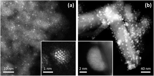 | ||
| Fig. 1 Experimental HAADF-STEM images of supported Pd–Ir and Au–Rh nanoparticles. (a) Image of 2 ± 1 nm Pd–Ir nanoparticles supported on γ-Al2O3. The catalyst was prepared through incipient wetness co-impregnation of the support with Pd and Ir acetylacetonates followed by thermal treatment in H2.7 The insert shows a high-resolution image of a single particle: the Z-contrast indicates a core–shell structure, consistent with an Ir-rich core and a Pd-rich shell. (b) Image of 4 ± 1 nm Au–Rh nanoparticles supported on rutile TiO2 nanorods. The sample was prepared through chemical co-reduction and sol immobilization, followed by treatment in H2 at 350 °C.18,22 The insert shows a high-resolution image of a single particle: the Z-contrast indicates a faceted Janus particle, with Rh at the interface between Au and the TiO2 substrate. | ||
This article is structured as follows. In Section 2 we present details of the models and calculation methods adopted. We report our results in Section 3: for free Au–Rh and Pd–Ir nanoalloys, comparing their mixing patterns (Section 3.1); for the TiO2-supported nanoalloys, comparing them with their unsupported counterparts (Section 3.2). Finally, conclusions and suggestions for future work are presented in Section 4.
2. Methodology
2.1. Models
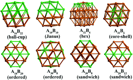
In our atomistic calculation, the (fcc packing) truncated octahedron (TO) has been chosen as the nanoparticle model to study Pd–Ir and Au–Rh nanoalloys. The TO structure is frequently adopted in theoretical and experimental studies,30,31 owing to its high symmetry (Oh) and the fact that real NP catalysts typically adopt this geometry. Because of the expense of performing DFT calculations for clusters with hundreds or thousands of atoms, only the sizes of 38 and 79 atoms are considered here to elucidate trends of structural stability for nanoalloys with different compositions and chemical arrangements, which enables predictions to be made for the larger experimental fcc-type NPs. Nanoalloys present increased structural complexity compared with unary NPs because of variability of composition and the many possible chemical arrangements, such as ordered, Janus, ball–cup, core–shell and sandwich configurations (see Fig. 2).23,25In the study of TiO2-supported 38-TO and 79-TO Au–Rh and Pd–Ir nanoalloys, a 3-layer rutile TiO2(110) slab (comprising 9 layers of atoms, with a total thickness of 0.92 nm) is chosen to investigate the effect of TiO2 on the nanoalloy particles. Pure clusters and nanoalloys are placed between bridging O rows of the TiO2(110) surface to maximise the metal-support interaction: supported Pd clusters are shown in Fig. 3. Three supported orientations are studied: position 1 – the TO cluster is edge-on to the TiO2(110) surface; position 2 – a TO (100) facet is parallel to the surface; position 3 – a TO (111) facet is parallel to the surface.
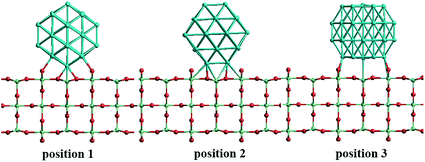 | ||
| Fig. 3 The three positions studied for 38-TO Pd–Ir and Au–Rh nanoalloy clusters (and their pure metal equivalents) adsorbed on the TiO2(110) surface. | ||
2.2. Calculations
All calculations are performed using the DFT method, as implemented in the Vienna ab initio Simulation Package (VASP).32 The interaction between valence electrons and ionic cores is described by the projector augmented wave (PAW) method.33,34 The generalized gradient approximation (GGA) is employed within the Perdew–Burke–Ernzerhof (PBE) parameterization for the exchange–correlation energy functional.35 All the calculations are spin-polarized, and the valence electrons are treated explicitly. To avoid spurious periodic interactions, the unsupported clusters are placed in a sufficiently large supercell to ensure ∼10 Å separation by vacuum. All calculated clusters (both free and supported) are locally geometrical optimized at the DFT level, where all cluster atoms, are relaxed until the forces on the atoms are lower than 0.01 eV Å−1, and the electronic ground states are determined by requiring a total energy convergence of 10−6 eV. For the TiO2-supported clusters, owing to the high computational cost of TiO2(110) slab relaxation, only the atoms in the top two layers of the TiO2 slab, directly in contact with the nanoclusters, are relaxed during the local minimization, the atoms in the bottom layer are frozen to model bulk atoms. However, the cluster geometries are fully relaxed when adsorbed on the partly frozen TiO2 slab.For the stability comparison of both Au–Rh and Pd–Ir nanoalloys with different compositions and different configurations, a mixing (or excess) energy term (Δ) is calculated using:
 | (1) |
The surface binding energy (Es-bind) of the Au–Rh and Pd–Ir NPs on the TiO2 surface is calculated as:
| Es-bind = Etot(NP|surf) − Etot(NP) − Etot(surf) | (2) |
3. Results and discussion
3.1. Free nanoalloys
The relative structural stabilities of free nanoalloys is determined by calculating the excess energies for different compositions and configurations. To enable comparison of the stabilities of NPs with different numbers of atoms, Fig. 4 shows the variation of the excess energy per atom (Δ/N) for Pd–Ir and Au–Rh nanoalloys (with N = 38 and 79 atoms) plotted against the percentage of Ir or Rh, respectively. For both systems, core–shell configurations, in which the Ir or Rh atoms occupy the core positions, are energetically favoured. On the other hand, for both systems the inverse core–shell structures, in which the other element (Pd or Au) occupies the core positions, were found to be the least stable. This is due to the higher cohesive and surface energies of Ir and Rh relative to Pd and Au.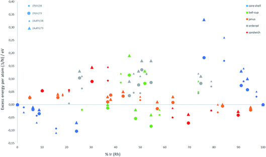 | ||
| Fig. 4 Excess energy per atom (Δ/N) versus atomic composition for 38-TO and 79-TO Pd–Ir and Au–Rh nanoalloys. | ||
In the more mixed ordered alloys, unlike for core–shell structures, both elements occupy similar numbers of core and surface positions (assuming no surface segregation occurs). Hence, all the ordered nanoalloys are relatively unstable, having high (positive) excess energies. However, Janus configurations, in which both elements again occupy similar numbers of core and surface positions, have excess energies per atom which are close to zero. For Pd–Ir and Au–Rh NPs, Janus configurations (which have a smaller number of heteronuclear interactions) are favoured over ordered (or random) mixed nanoalloys because the Ir–Ir and Rh–Rh bonds are stronger than the heteronuclear (Pd–Ir and Au–Rh) bonds. The excess energies of Janus structures tend to be slightly negative for Ir- and Rh-rich clusters and slightly positive for Pd- and Au-rich clusters. This is because in Janus NPs, the metal which is present in excess occupies a higher proportion of core sites, which is favourable when this corresponds to the strongest binding element (Ir or Rh).
Fig. 4 shows that, after core–shell configurations, the second most stable chemical arrangements are ball–cup configurations, which lie between the core–shell and Janus configurations. Ball–cup configurations are similar to Janus structures, but they have a curved (rather than planar) interface between the two elements. Thus, for ball–cup structures, one element occupies more core positions (forming the “ball”) and the other element occupies more surface positions (forming the “cup”). When the ball element is the stronger binding metal (Ir or Rh) the excess energy is negative, while it is positive if the ball element is Pd or Au.
In sandwich structures, a slab of one metal is sandwiched between layers of the other metal. The central slab has a higher proportion of atoms in core sites than the sandwiching layers, which occupy more surface sites. If the sandwiching element is only one layer thick, the sandwich structure can also be seen as an incomplete core–shell configuration. As for ball–cup structures, sandwich configurations have negative excess energies if the stronger binding elements (Ir and Rh) are in the central slab.
These results show that the strongly binding Ir and Rh atoms preferentially occupy core sites, but relatively stable configurations can also arise if they also occupy surface sites in which they form a high number of Ir–Ir or Rh–Rh bonds. Comparing the two nanoalloy systems, the excess energies of Pd–Ir NPs are generally lower (more negative or less positive) than Au–Rh, probably because Ir–Ir bonds are stronger than Rh–Rh bonds. The exception to this trend is for 38-atom core–shell configurations, where RhcoreAushell (Rh@Au) structures have more negative excess energies, which may be due to the lower surface energy of Au (1.5 J m−2) compared to Pd (2.1 J m−2).36
3.2. Supported nanoalloys
To understand the cluster–support binding strength and mixing properties of Pd–Ir and Au–Rh nanoalloys supported on high-surface-area metal oxides, we calculate the surface binding energies (Es-bind) and excess energies (Δ) of 38-atom TO Pd–Ir and Au–Rh clusters on a TiO2(110) slab, as shown in Fig. 5 and 6. Here, for simplicity, only pure clusters (Pd38, Ir38, Au38 and Rh38), complete core–shell (Pd32Ir6 = Ir@Pd, Pd6Ir32 = Pd@Ir, Au32Rh6 = Rh@Au, Au6Rh32 = Au@Rh) and 1![[thin space (1/6-em)]](https://www.rsc.org/images/entities/char_2009.gif) :
:![[thin space (1/6-em)]](https://www.rsc.org/images/entities/char_2009.gif) 1 Janus (Pd19Ir19 = Janus-PdIr and Au19Rh19 = Janus-AuRh) NPs are considered. The terminology Janus-M will be used to indicate that the Janus particle is in contact with the TiO2 substrate predominantly through metal M. As mentioned previously, three supported positions are considered (see Fig. 3).
1 Janus (Pd19Ir19 = Janus-PdIr and Au19Rh19 = Janus-AuRh) NPs are considered. The terminology Janus-M will be used to indicate that the Janus particle is in contact with the TiO2 substrate predominantly through metal M. As mentioned previously, three supported positions are considered (see Fig. 3).
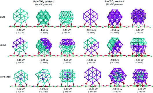
Fig. 5 shows the surface binding geometries and energies, for the pure NPs and the core–shell and Janus nanoalloys, on the TiO2(110) surface. For comparison and analysis, we divide all considered nanoclusters into two groups, those with Pd–TiO2 contacts (pure Pd, Ir@Pd and Janus-Pd), and those with Ir–TiO2 contacts (pure Ir, Pd@Ir and Janus-Ir). The analogous Au–Rh|TiO2 configurations are generated by replacing Pd with Au and Ir with Rh.
A detailed discussion of the structures and energetics of the (Au–Rh)38|TiO2 system has been presented elsewhere.24 Similar to Rh (Es-bind = −8.98 eV), both pure Pd and Ir NPs prefer to be supported on position 1, with surface binding energies of −5.46 eV and −10.36 eV, respectively. In contrast, the pure Au NP binds preferentially in position 3 (Es-bind = −5.88 eV). The more negative surface binding energy for Ir compared with Pd is due to the stronger Ir–O interaction (analogous to the stronger Rh–O interaction in the Au–Rh|TiO2 system). For the same reason, the surface binding energies of the Pd–Ir nanoalloys with Ir in contact with the surface (Pd@Ir and Janus-Ir) are significantly larger in magnitude (−10.38 eV and −10.36 eV, respectively) than for those with Pd in contact (Ir@Pd = −5.92 eV; Janus-Pd = −6.24 eV). These results are consistent with the slightly higher Ir–O bond strength (about 89 kcal mol−1) compared to Pd–O (86 kcal mol−1).37 As for the pure Ir NP, position 1 is found to be the favoured binding mode for the Ir-bound nanoalloys. Position 1 is favoured for Ir@Pd (as well as the pure Pd NP), but the favoured binding mode for Janus-Pd is position 2. In the Au–Rh system, all Rh-bound NPs bind preferentially in position 1, while all Au-bound NPs bind in position 3.
The surface binding energies of the Janus-Pd and Ir@Pd core–shell NPs (−6.24 eV and −5.92 eV, respectively) are larger in magnitude than for the pure Pd cluster (−5.46 eV), indicating a synergistic effect of Ir atoms on the surface-binding of Pd-rich nanoalloys. This is in contrast to the Au–Rh system, where strain effects dominate and the extra rigidity induced by Rh (as Rh–Au bonds are much stronger than Au–Au bonds) leads to weakening of the Au-surface interactions because the Au structure cannot rearrange to form a better epitaxial interaction with the TiO2(110) surface.24 We conclude that the strengthening of Pd-surface interactions in the Pd–Ir|TiO2 system is mainly electronic in origin. The lower surface binding energy of Ir@Pd compared to Janus-Pd may be due in part to strain effects, because any Ir-induced rigidification would be expected to be greater for the core–shell structure in which all the shell Pd atoms are in contact with core Ir atoms. However, it is possible that the extra stability of the Janus-Pd arrangement may be due to the presence of Ir–O interactions, as shown in Fig. 5.
For the Ir-bound structures, in the most stable binding mode (position 1 in each case), there is very little change in surface binding energy for the Janus-Ir (−10.36 eV) and Pd@Ir (−10.38 eV) nanoalloys compared with the pure Ir NP (−10.36 eV). However, for the less stable binding modes (positions 2 and 3) there are significant increases in surface binding energy for the nanoalloys, such that the difference in energy between position 1 and position 2, drops from 1.85 eV (pure Ir) to 0.76 eV (Janus-Ir) and 0.28 eV (Pd@Ir). This stabilisation of the less favourable binding positions, which is also observed for the Au@Rh nanoalloy but not Janus-Rh,20 may be due to facilitation of Ir deformation due to replacing strong Ir–Ir bonds with weaker Ir–Pd bonds, but electronic effects cannot be ruled out and this does not explain why such an effect is not seen in position 1.
In a previous study of the effect of alloying on the adsorption of CO and O2 on free 38- and 79-atom Au–Rh nanoalloys, we found that strain effects can also be evoked to explain the decrease in the molecular adsorption energy on Au in the presence of Rh and the increase in the adsorption energy on Rh in the presence of Au.19 Au–Rh alloying was also calculated to lead to a decrease in the O2 dissociation barrier on Rh but an increase on Au. Consistent with our findings (above) on the effect of Pd–Ir alloying on surface binding energies, our previous calculations of the adsorption energies of CO on 38-atom Pd–Ir nanoalloys showed that electronic effects (as measured by charge transfer and shifts in the d-band centre) were required to explain the results.21
The effect of surface–NP interactions on the NP structure can be appreciated by considering the changes in the average metal–metal (M–M) bond distance for those metal atoms that are in contact with the TiO2 substrate. M–M bond distances are expected to increase (reflecting weakening of the M–M bonds) as the surface-metal interactions get stronger. Table 1 shows the average M–M bond distances in (111) facets (both at the interface and far from the interface) of 38-TO NPs for free and TiO2 supported pure, core–shell and Janus structures (the supported NPs are all in position 3, where a (111) facet of the 38-TO structure is in contact with the TiO2 surface). Relative to the free particles, M–M bond distances far from the NP–substrate interface decrease slightly or remain unchanged in all cases. However, for all structures, the M–M bond distances increase significantly within the metal layer which is at the interface. The lengthening of interfacial Pd and Au M–M bonds is typically larger than for Ir and Rh, reflecting the weaker, more easily deformed Pd–Pd and Au–Au bonds. For Pd (Au) in contact with the TiO2 surface, the increase in bond length follows the order Janus > pure > core–shell. As discussed above, the Ir (Rh) core makes the core–shell NP more rigid, due to the introduction of stronger Ir–Pd (Rh–Au) bonds, which also explains why the surface binding strengths (see Fig. 5) of the Janus NPs (Janus-Pd and Janus-Au) are stronger (having more negative surface binding energies) than those of the core–shell clusters (Ir@Pd and Rh@Au) (it should be noted that for the Janus and pure NPs the interfacial Pd (Au) atoms only form M–M bonds to atoms of the same type). For Ir (Rh) at the interface, the increase in M–M bond length is larger for both the Janus-Ir (Janus-Rh) and Pd@Ir (Au@Rh) structures than for pure Ir (Rh), due to the increased deformability of the NP arising from the introduction of weaker heteronuclear (Ir–Pd or Rh–Au) bonds. As shown in Fig. 5, this is accompanied by increased surface binding strengths for the Janus and core–shell nanoalloy configurations, relative to the pure Ir or Rh NPs.
| Bond type and structure | Free NP | Supported NP (far from interface) | Supported NP (at interface) |
|---|---|---|---|
| Au–Au | |||
| Au38 | 2.82 | 2.78 | 2.97 |
| Rh@Au | 2.79 | 2.80 | 2.91 |
| Janus-AuRh | 2.84 | 2.82 | 3.06 |
![[thin space (1/6-em)]](https://www.rsc.org/images/entities/char_2009.gif) ![[thin space (1/6-em)]](https://www.rsc.org/images/entities/char_2009.gif) |
|||
| Rh–Rh | |||
| Rh38 | 2.62 | 2.62 | 2.73 |
| Au@Rh | 2.66 | 2.62 | 2.70 |
| Janus-AuRh | 2.62 | 2.62 | 2.67 |
![[thin space (1/6-em)]](https://www.rsc.org/images/entities/char_2009.gif) |
|||
| Pd–Pd | |||
| Pd38 | 2.72 | 2.70 | 2.83 |
| Ir@Pd | 2.70 | 2.70 | 2.76 |
| Janus-PdIr | 2.74 | 2.79 | 2.89 |
![[thin space (1/6-em)]](https://www.rsc.org/images/entities/char_2009.gif) |
|||
| Ir–Ir | |||
| Ir38 | 2.62 | 2.62 | 2.67 |
| Pd@Ir | 2.62 | 2.62 | 2.70 |
| Janus-PdIr | 2.60 | 2.62 | 2.68 |
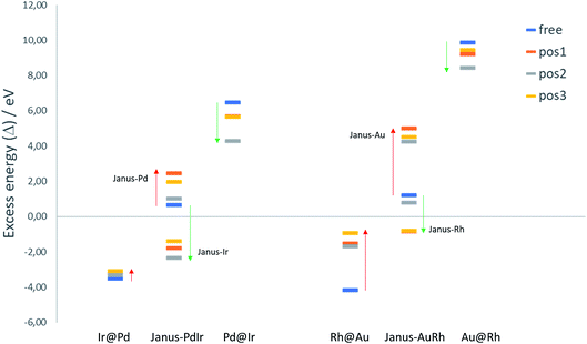
To evaluate the relative structural stabilities of the TiO2-supported NPs, taking into account variation in NP stability and NP–surface interaction, we have calculated the excess energies of the supported core–shell and Janus configurations for 38-atom Pd–Ir and Au–Rh nanoalloys in the three binding positions. They are compared with the corresponding free nanoalloys in Fig. 6. It is clear that the “inverse” core–shell Pd@Ir and Au@Rh nanoalloys adsorbed on TiO2 are stabilised significantly in all supported positions (having less positive values than the corresponding free clusters). However, the supported excess energies are still highly positive because of the inherent instability of these configurations for the free NPs (arising from the high surface energies of the Rh and Ir shell metals: 2.7 and 3.0 J m−2, respectively).36 The more favoured core–shell configurations (Ir@Pd and Rh@Au) have negative excess energies, but due to their relatively unfavourable interactions with the TiO2 surface, their excess energies are less negative than the corresponding free core–shell NPs. However, this difference is much smaller for Ir@Pd than Rh@Au, due to the previously mentioned weakening of the Au-surface interaction induced through Au–Rh alloying.
For the Janus-PdIr nanoalloy, due to the stronger Ir–O interaction (and hence more negative surface binding energies), the Janus-Ir configuration has a significantly more negative excess energy than the free Janus NP, for all binding positions. Conversely, Janus-Pd is destabilized, having a more positive mixing energy than the free Janus NP, due to the weaker Pd-surface interaction. Similarly, Janus-Rh is stabilised relative to the free Janus-AuRh NP and Janus-Au is destabilised. The energy differences between the supported Janus-Ir and Ir@Pd NPs and between the supported Janus-Rh and Rh@Au NPs are smaller than for the free NPs, which can be described as support-induced stabilisation of Janus type clusters. The relative support stabilisation of Janus particles is greater for Au–Rh than Pd–Ir because of the significantly weaker binding of the Rh@Au core–shell NP (−2.89 eV) on the TiO2 surface compared to pure Au (−5.46 eV), while Ir@Pd binds more strongly to the surface (−5.92 eV) than the pure Pd NP (−5.46 eV).
It should be noted that the relative ordering of the excess energies of the nanoalloys in the three binding positions does not always reflect the order of surface binding energies, because the excess energies are defined as the energy of the supported alloy NP relative to the supported pure clusters, which may not always favour the same binding position. For example, the significant destabilisation of the pure Pd and Ir NPs in position 2, and the fact that position 2 has a surface binding energy which is close to that of position 1 (or more negative in the case of Janus-Pd), results in position 2 having a more negative excess energy for all supported Pd–Ir nanoalloys.
4. Conclusions
The mixing properties of free and TiO2(110)-supported Pd–Ir and Au–Rh NPs have been investigated theoretically using DFT calculations. In agreement with the lower surface and cohesive energies of Pd (Au) than Ir (Rh), the excess energy calculations show that Ir@Pd and Rh@Au core–shell configurations are the most stable. Ball–cup structures (with Ir or Rh partially encapsulated by Pd or Au) are the second most stable configurations, with the inverse core–shell Pd@Ir and Au@Rh configurations being highest in energy. The general stability order for Pd–Ir nanoalloys is Ir@Pd > PdcupIrball > sandwich-Pd > Janus > sandwich-Ir > ordered ≈ PdballIrcup > Pd@Ir, with the same ordering for Au–Rh NPs (where Au replaces Pd and Rh replaces Ir).The surface binding strength of Pd–Ir nanoalloys bound to the TiO2(110) surface through the Ir atoms is greater than for Pd-surface binding (analogous to Au–Rh nanoalloys, where Rh-surface binding is stronger than Au-surface binding), due to the stronger Ir–O interactions. However, the presence of Ir atoms increases the Pd-surface binding strength relative to the pure Pd cluster (in contrast to the Au–Rh system, where the presence of Rh weakens the Au-surface interaction). With the exception of Au-surface binding (where binding position 3, with a (111) facet parallel to the TiO2(110) surface, is favoured), and the Janus-Pd arrangement (which favours position 2), all other Pd-, Ir- and Rh-surface configurations bind preferentially in position 1 (where the NP binds in an edge-on fashion). There is good correlation between trends in cluster surface binding energies and surface-induced lengthening of metal–metal bond lengths. The excess energies of the supported inverse core–shell (Pd@Ir and Au@Rh) and (Ir-bound and Rh-bound) Janus nanoalloys are much lower than their unsupported counterparts and become closer in energy to the core–shell (Ir@Pd and Rh@Au) configurations, which are favoured for the free nanoalloys.
These results show that the presence of a strongly interacting substrate, such as TiO2, is expected to influence the chemical arrangement of nanoalloys. Experiments have shown that titania-supported Au–Rh (Fig. 1b)18,22 and Au–Ir38 NPs adopt Janus-like structures. This allows them to anchor to the oxide via the most reactive element (Rh or Ir), while preserving a segregated configuration: the Janus configuration becoming energetically competitive with the core–shell structure. Practically, strengthening the NP–substrate interaction leads to a strong resistance to sintering under severe catalytic conditions. The present results have general significance as they may apply to other pairs of bulk-immiscible metals, and may suggest a general strategy for stabilising metal NPs on oxide supports through the addition of even a small-amount of a suitable element.
In future work, we will extend our approach to study other nanoalloy systems, including those involving cheaper, earth abundant metals. We will also investigate the effect of various oxide substrates (e.g. TiO2 and Al2O3) on the strength of adsorption of small reactive species such as H2, O2 and CO on nanoalloys, as well as evaluating the effects of NP composition, size and chemical arrangement, and the influence of the support, on bond dissociation barriers and catalytic reaction pathways.
Conflicts of interest
There are no conflicts to declare.Acknowledgements
T-EF is grateful for funding from the Graduate School of Xiamen University. RLJ and ID acknowledge support through EPSRC Critical Mass Grant (EP/J010804/1) TOUCAN. Calculations were performed on the following HPC facilities: The University of Birmingham Bluebear HPC facility (see http://www.bear.bham.ac.uk/bluebear for more details) and the UK’s national HPC facility, ARCHER, both via membership of the UK’s HPC Materials Chemistry Consortium, which is funded by EPSRC (EP/L000202), and via the TOUCAN grant. ZYL acknowledges Royal Society International Exchange Grant IE140712. LP acknowledges the French METSA network and Corinne Ulhaq (IPCMS, Strasbourg) for STEM imaging of Pd–Ir nanoparticles.References
- R. W. Murray, Chem. Rev., 2008, 108, 2688 CrossRef PubMed.
- Z.-Y. Zhou, N. Tian, J.-T. Li, I. Broadwell and S.-G. Sun, Chem. Soc. Rev., 2011, 40, 4167 RSC.
- R. Ferrando, J. Jellinek and R. L. Johnston, Chem. Rev., 2008, 108, 845 CrossRef PubMed.
- S. Alayoglu, A. U. Nilekar, M. Mavrikakis and B. Eichhorn, Nat. Mater., 2008, 7, 333 CrossRef PubMed.
- L. Kesavan, R. Tiruvalam, M. H. A. Rahim, M. I. bin Saiman, D. I. Enache, R. L. Jenkins, N. Dimitratos, J. A. Lopez-Sanchez, S. H. Taylor, D. W. Knight, C. J. Kiely and G. J. Hutchings, Science, 2011, 331, 195 CrossRef PubMed.
- S. Khanal, N. Bhattarai, J. J. Velázquez-Salazar, D. Bahena, G. Soldano, A. Ponce, M. M. Mariscal, S. Mejía-Rosales and M. José-Yacamán, Nanoscale, 2013, 5, 12456 RSC.
- F. Morfin, S. Nassreddine, J. L. Rousset and L. Piccolo, ACS Catal., 2012, 2, 2161 CrossRef.
- C. Zlotea, F. Morfin and T. S. Nguyen, Nanoscale, 2014, 6, 9955 RSC.
- Y. Yuan, N. Yan and P. J. Dyson, ACS Catal., 2012, 2, 1057 CrossRef.
- S. Guo, S. Zhang and S. Sun, Angew. Chem., Int. Ed., 2013, 52, 8526 CrossRef PubMed.
- W. Yu, M. D. Porosoff and J. G. Chen, Chem. Rev., 2012, 112, 5780 CrossRef PubMed.
- C. Wang, H. Daimon, T. Onodera, T. Koda and S. Sun, Angew. Chem., Int. Ed., 2008, 47, 3588 CrossRef PubMed.
- N. Tian, Z.-Y. Zhou, S.-G. Sun, Y. Ding and Z. L. Wang, Science, 2007, 316, 732 CrossRef PubMed.
- H. Zhu, S. Zhang, S. Guo, D. Su and S. Sun, J. Am. Chem. Soc., 2013, 135, 7130 CrossRef PubMed.
- K. J. Andersson, F. Calle-Vallejo, J. Rossmeisl and I. Chorkendorff, J. Am. Chem. Soc., 2009, 131, 2404 CrossRef PubMed.
- F. Tao, M. E. E. Grass, Y. Zhang, D. R. R. Butcher, J. R. R. Renzas, Z. Liu, J. Y. Y. Chung, B. S. S. Mun, M. Salmeron and G. A. A. Somorjai, Science, 2008, 322, 932 CrossRef PubMed.
- F. Tao, M. E. Grass, Y. Zhang, D. R. Butcher, F. Aksoy, S. Aloni, V. Altoe, S. Alayoglu, J. R. Renzas, C. K. Tsung, Z. Zhu, Z. Liu, M. Salmeron and G. A. Somorjai, J. Am. Chem. Soc., 2010, 132, 8697 CrossRef PubMed.
- Z. Konuspayeva, P. Afanasiev, T.-S. Nguyen, L. Di Felice, F. Morfin, N.-T. Nguyen, J. Nelayah, C. Ricolleau, Z. Y. Li, J. Yuan, G. Berhault and L. Piccolo, Phys. Chem. Chem. Phys., 2015, 17, 28112 RSC.
- T. S. Nguyen, D. Laurenti, P. Afanasiev, Z. Konuspayeva and L. Piccolo, J. Catal., 2016, 344, 136 CrossRef.
- Z. Konuspayeva, G. Berhault, P. Afanasiev, T.-S. Nguyen, S. Giorgio and L. Piccolo, J. Mater. Chem. A, 2017, 5, 17360 Search PubMed.
- L. Liu, X. Guan, Z. Li, X. Zi, H. Dai and H. He, Appl. Catal., B, 2009, 90, 1 CrossRef.
- L. Piccolo, Z. Y. Li, I. Demiroglu, F. Moyon, Z. Konuspayeva, G. Berhault, P. Afanasiev, W. Lefebvre, J. Yuan and R. L. Johnston, Sci. Rep., 2016, 6, 35226 CrossRef PubMed.
- I. Demiroglu, Z. Y. Li, L. Piccolo and R. L. Johnston, Catal. Sci. Technol., 2016, 6, 6916 Search PubMed.
- I. Demiroglu, Z. Y. Li, L. Piccolo and R. L. Johnston, Comput. Theor. Chem., 2017, 1107, 142 CrossRef.
- T.-E. Fan, I. Demiroglu, H. A. Hussein, T.-D. Liu and R. L. Johnston, Phys. Chem. Chem. Phys., 2017, 19, 27090 RSC.
- T. B. Massalski and H. Okamoto, Binary Alloy Phase Diagrams, ASM International, Ohio, 1990 Search PubMed.
- S. N. Tripathi, S. R. Bharadwaj and M. S. Chandrasekharaiah, J. Phase Equilib., 1991, 12, 603 CrossRef.
- E. R. Essinger-Hileman, D. DeCicco, J. F. Bondi and R. E. Schaak, J. Mater. Chem., 2011, 21, 11599 RSC.
- A. Malouche, Y. Oumellal, C. M. Ghimbeu, A. M. de Yuso and C. Zlotea, J. Nanopart. Res., 2017, 19, 270 CrossRef.
- Y. Sun, B. Wiley, Z. Y. Li and Y. Xia, J. Am. Chem. Soc., 2004, 126, 9399 CrossRef PubMed.
- F. Baletto, C. Mottet and R. Ferrando, Phys. Rev. Lett., 2003, 90, 135504 CrossRef PubMed.
- G. Kresse and J. Hafner, Phys. Rev. B: Condens. Matter Mater. Phys., 1993, 47, 558 CrossRef.
- P. E. Blöchl, Phys. Rev. B: Condens. Matter Mater. Phys., 1994, 50, 17953 CrossRef.
- G. Kresse and D. Joubert, Phys. Rev. B: Condens. Matter Mater. Phys., 1999, 59, 1758 CrossRef.
- J. P. Perdew, K. Burke and M. Ernzerhof, Phys. Rev. Lett., 1996, 77, 3865 CrossRef PubMed.
- F. R. de Boer, R. Boom, W. C. M. Mattens, A. R. Miedema and A. K. Niessen, Cohesion in Metals: Transition Metal Alloys, North-Holland Physics Publishing, Amsterdam, 1989 Search PubMed.
- M. Ziauddin, G. Veser and L. D. Schmidt, Catal. Lett., 1997, 46, 159 CrossRef.
- C. W. Han, P. Majumdar, E. E. Marinero, A. Aguilar-Tapia, R. Zanella, J. Greeley and V. Ortalan, Nano Lett., 2015, 15, 8141 CrossRef PubMed.
| This journal is © The Royal Society of Chemistry 2018 |

