The decarbonisation of petroleum and other fossil hydrocarbon fuels for the facile production and safe storage of hydrogen†
Xiangyu
Jie
 a,
Sergio
Gonzalez-Cortes
 a,
Tiancun
Xiao
 *a,
Benzhen
Yao
 a,
Jiale
Wang
b,
Daniel R.
Slocombe
 c,
Yiwen
Fang
 a,
Noah
Miller
a,
Hamid A.
Al-Megren
d,
Jonathan R.
Dilworth
a,
Noah
Miller
a,
Hamid A.
Al-Megren
d,
Jonathan R.
Dilworth
 a,
John M.
Thomas
*e and
Peter P.
Edwards
 *a
*a
aKing Abdulaziz City for Science and Technology (KACST) – Oxford Centre of Excellence in Petrochemicals (KOPRC), Inorganic Chemistry Laboratory, Department of Chemistry, University of Oxford, South Parks Road, Oxford OX1 3QR, UK. E-mail: xiao.tiancun@chem.ox.ac.uk; peter.edwards@chem.ox.ac.uk
bDepartment of Materials, University of Oxford, Parks Road, Oxford, OX1 3PH, UK
cSchool of Engineering, Cardiff University, Queen's Buildings, The Parade, Cardiff, CF24 3AA, UK
dPetrochemical Research Institute, King Abdulaziz City for Science and Technology, P.O. Box 6086, Riyadh 11442, Kingdom of Saudi Arabia
eDepartment of Materials Science and Metallurgy, University of Cambridge, 27 Charles Babbage Road, Cambridge, CB3 0FS, UK. E-mail: jmt2@cam.ac.uk
First published on 24th October 2018
Abstract
The importance of extracted and refined fossil carbonaceous fuels (petroleum, diesel etc.) to the development of human society cannot be overestimated. These natural resources have improved billions of lives, worldwide, in providing accessible, relatively inexpensive energy at nearly every scale. Notwithstanding the credible advances in renewable energy production over the past decade or so, the aerial combustion of coal, natural gas and liquid fossil fuels, given humankinds insatiable demand for power, will continue to be the ready source of more than 85% of the world's energy in the foreseeable and possibly the distant future. Human activities based on the combustion of fossil fuels, however, has led to significant anthropogenic emissions of carbon dioxide (CO2) to the atmosphere – and that fact is now seen as the major contributor to global warming and climate change. To stabilise global mean temperatures will depend on the ultimate transformation of humankind's energy system to one that does not introduce CO2 into the atmosphere. The hydrogen economy has long been mooted as a route to achieving the required net-zero emissions energy future. Paradoxically, fossil fuel sources such as petroleum, crude and extra-heavy crude oil, petrol, diesel and methane are reported here to produce high volumes of high-purity hydrogen through their microwave-initiated catalytic dehydrogenation using fine iron particles. The co-product of this dehydrogenation process, solid carbon, can be safely stored underground in perpetuity or converted in future to valuable hydrocarbons and other materials. Through their catalytic dehydrogenation to yield carbon-free hydrogen – rather than through their aerial combustion to produce carbon dioxide – petroleum and other fossil fuels can now serve as an energy pathway to stabilising global mean temperatures.
Broader contextThe recent IPCC Report highlights that limiting global warming to 1.5 °C above pre-industrial levels necessitates decarbonisation of the world's energy systems, culminating in zero CO2 emissions by the middle of the century. Such a transition is conventionally viewed in terms of non-fossil wind, solar and nuclear as renewable or sustainable energy sources. However, given the ever-increasing use of fossil fuels, the daunting necessity also exists of capturing and storing massive amounts of aerial CO2. The advances reported in our proof-of-principle study offer a fundamentally different approach to currently-advocated methods of diminishing the liberation of CO2. It still entails the use of the abundant sources of petroleum and other fossil fuels but, by use of microwave-stimulated catalysts of an inexpensive variety, it now generates clean hydrogen fuel and elemental carbon. This paves the way to the hydrogen economy using petroleum and fossil fuels as H2 stores and enables the residual, solid carbon to be stored in perpetuity or converted to widely-used, high-value products, such as syngas, carbon nanotubes or graphitic electrode materials. Fossil fuel decarbonization, therefore, is a route to mitigating global warming. |
Introduction
The extracted and refined hydrocarbon fossil fuels, petrol and diesel are quite simply unrivalled in terms of their energy density and widespread ease of use and storage. These hydrocarbon energy sources are easily burned in air to produce copious amounts of easily-controlled heat.1 Indeed, our whole industrial society is based upon their oxidation/combustion reactions. These naturally occurring carbonaceous fuels have increased our comfort, longevity, and affluence. However, it is now recognised that their usage may come at a cost; the aerial combustion of these fuels leads to significant emissions of CO2 to the atmosphere, estimated at 32.5 giga-tons (Gt) of CO2 in 2017 alone.2 Therefore, it is platitudinous to remark that there may be a clear need to shift to alternative fuels, which provide energy without adding CO2 to the atmosphere.3–5 One of the principal reasons why progress has been so slow towards what is recognised as the ultimate of such a sustainable energy transition – the hydrogen economy6–13 – devolves to the fact that there is no readily available, massive source of “natural” hydrogen. Furthermore, to date, no reliable means exists for storing hydrogen so that it can be rapidly released – safely, and on demand-for fuel cell and other applications.6,14–16Here, we demonstrate that high purity hydrogen, in high volume, can be rapidly produced using inexpensive fine iron particle catalysts through the microwave-initiated, catalytic dehydrogenation of petroleum and other fossil fuels, ranging from extra-heavy crude oil, crude oil through diesel and petrol, and finally to methane.
Results and discussion
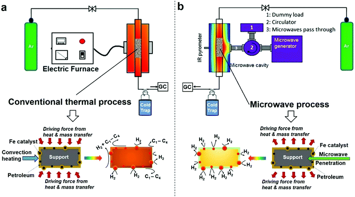
It is important to set out the fundamental differences between conventional and microwave (MW) heating processes, particularly in regard to the heating/necessary activation of included or dispersed metal catalyst particles in a low thermal conductivity host medium such as a liquid hydrocarbon. In a conventional heating process, thermal energy is transferred to the catalyst particles through convection, conduction and radiation of external heat from the outer surfaces of a container into the host material itself. In contrast, microwave energy is delivered directly to the microwave-absorbing/microwave-receptive/component through molecular interactions – and in the case of the important metallic catalyst particles of interest here, through conduction–electron interactions with the electromagnetic field. Heat transfer by conventional heating is transferred through time-dependent, developing thermal gradients. However, in microwave heating, electromagnetic energy is directly transferred, and heat is instead generated, to microwave absorbing matter within the sample by electromagnetic coupling through a variety of charge-dynamical processes. We hope to illustrate that this fundamental difference results in important advantages in using microwaves to initiate and promote the catalytic dehydrogenation of hydrocarbon fuels by microwave-receptive/microwave-absorbing/metal catalyst particles.The experimental set-up of both conventional thermal process and our purpose-built microwave-catalytic reactor are shown schematically in Fig. 1 with further details presented in the Experimental section; and the detailed compositional analysis of petroleum samples including extra-heavy crude oil, crude oil, diesel and petrol supplied by Saudi Aramco are given in ESI.†
Compared to the conventional heating process in which the dispersed iron catalyst is gradually heated by convection heating of, and heat transfer from, the surrounding hydrocarbon fluid, microwave irradiation directly and preferentially interacts with the iron catalysts without significantly heating up the bulk of the hydrocarbon feedstock (an inefficient microwave absorber) (Fig. 1). This causes a rapid heating of the microwave-absorbing metal catalyst particles themselves and may potentially increase the resulting product selectivity itself. In addition, the applied (fluctuating) microwave field will induce a temperature gradient over the surface of individual metal catalyst particles that enhances the molecular diffusion of the incoming hydrocarbon reactant and improves the transport of the resulting active species in any reaction system.17,18 It is recognised that this changes the overall reaction rate under microwave conditions, as compared to that with conventional, thermal heating.
The difference in the microwave and thermal heating process is also evident in the heat transfer.18 Under microwave irradiation, the microwave absorbing iron catalyst particle itself heats rapidly and transfers the generated heat itself to the surrounding support and host fossil fuel medium. In contrast, in a conventional thermal process, heat transfer to the catalyst particle must first be transported through the surrounding hydrocarbon fluid, with heat finally arriving at metal catalyst particle based purely on convection heating of the “host” low-thermal conductivity hydrocarbon medium. This heat transfer through the hydrocarbon medium finally serves to raise the temperature of, say, an iron catalyst particle to the appropriate catalytic reaction temperature. We will demonstrate that the microwave-initiated catalytic process minimises various catalytic side reactions, whilst increasing the selectivity of the hydrogen production (Fig. 1). In contrast, under classical convection/thermal heating, the temperature of the hydrocarbon surroundings is obviously higher than the catalyst as the process begins and develops. Thus, the host substance (here the hydrocarbon) could either self-decompose or decompose over the catalyst/support and this leads to different products in the catalytic process. This important aspect will be demonstrated in our detailed study of diesel dehydrogenation.
Hydrogen production characteristics from petroleum and fossil hydrocarbons
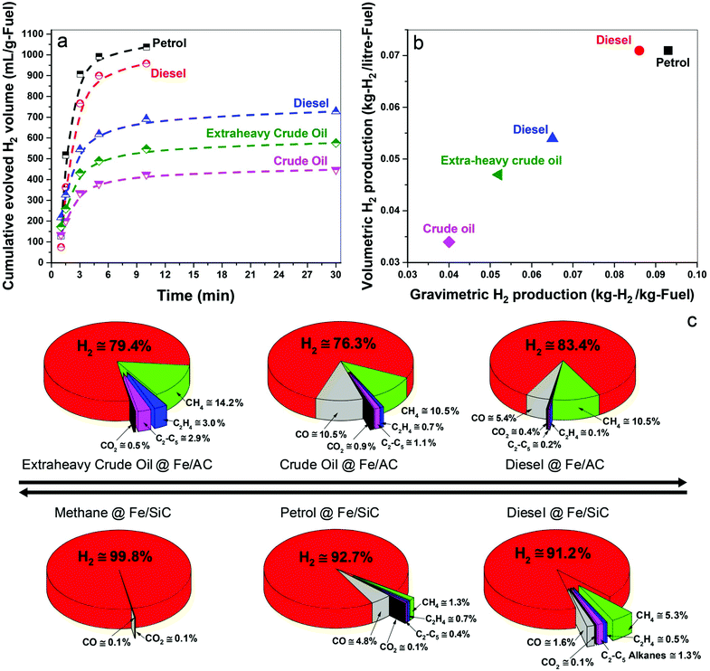
In Fig. 2a we show the time-dependent hydrogen evolution arising from the microwave-initiated dehydrogenation of both crude and extra-heavy crude oils and various fossil fuels using fine iron catalyst particles (typically 100 nm diameter) on the support materials of either activated carbon (AC) or silicon carbide (SiC). For the simplest comparisons, we used comparable weight% loading levels of the liquid fossil feedstocks on the same support.Activated carbon is established as an excellent microwave absorber or receptor whilst silicon carbide is characterised by its superior mechanical thermal and dielectric properties which, coupled to exceptional chemical inertness, avoids any complicating issues that may arise with activated carbon support materials.
Immediately at the very initiation of microwave irradiation of the samples, a considerable volume of high-purity hydrogen was readily extracted from the petroleum and heavy liquid feedstocks, and that typically in periods of about 3 minutes. We find a selectivity of over 90% for hydrogen in the exiting gas stream following this dehydrogenation of methane, petrol and diesel; selectivity is defined here as the volume% of the particular product composition of the total gaseous products.
For the heavier, and obviously inherently more complex crude and extra-heavy crude oil (see ESI†), the selectivity of evolved hydrogen is decreased to ca. 75–85%. Although less hydrogen is produced from these heavy feedstocks, microwave-initiated catalytic dehydrogenation is clearly still highly effective. Due to the inevitable extraneous or residual oxygen contained in the fuel feedstocks, the catalysts and also their supports, the production of CO and CO2 in very low concentrations cannot be avoided under our present experimental conditions.19,20
The dehydrogenation of methane to hydrogen and solid elemental carbon reached values of 80% conversion through this microwave-initiated catalytic dehydrogenation process. Corresponding quantitative conversion estimates for petroleum or crude oils are obviously more difficult since they are complex, multicomponent mixtures.21 For example, petroleum (or crude oil) is a complex, naturally occurring liquid mixture containing mostly hydrocarbons, but also containing some compounds of oxygen, nitrogen and sulphur.
Notwithstanding, we report that hydrogen masses of 0.04, 0.051, and 0.065 kg were extracted from 1 kg of crude oil, extra-heavy crude oil and diesel, respectively, over Fe/AC catalysts (Fig. 2b), illustrating the efficacy of the microwave-initiated catalytic dehydrogenation process. Higher levels of hydrogen production, 0.086 and 0.093 kg of hydrogen were liberated from 1 kg of diesel and petrol, respectively, over Fe/SiC catalysts, we will subsequently return to a discussion of these hydrocarbons as natural hydrogen storage materials themselves.
Parametric studies of the microwave-initiated dehydrogenation of diesel fuel
For detailed studies, we chose diesel as a well-characterised hydrocarbon fuel product derived from petroleum. The fuel consisted of mainly n-alkanes from C12 to C21 (89%) with some oxygen containing compounds (11%) such as dodecanol and methyl octadecenoate etc.; all constituents were identified by gas chromatography-mass spectrometry (GCMS) (Table S1, ESI†).Under the microwave-initiated process, diesel fuel was rapidly dehydrogenated over the Fe/SiC catalyst (Fig. 2). Hydrogen selectivity exceeded 91% in the evolved gases with less than a fraction of a percent of adventitious CO2. Small alkanes, mainly methane, comprised ca. 7 vol% of the remainder of the exit gases.
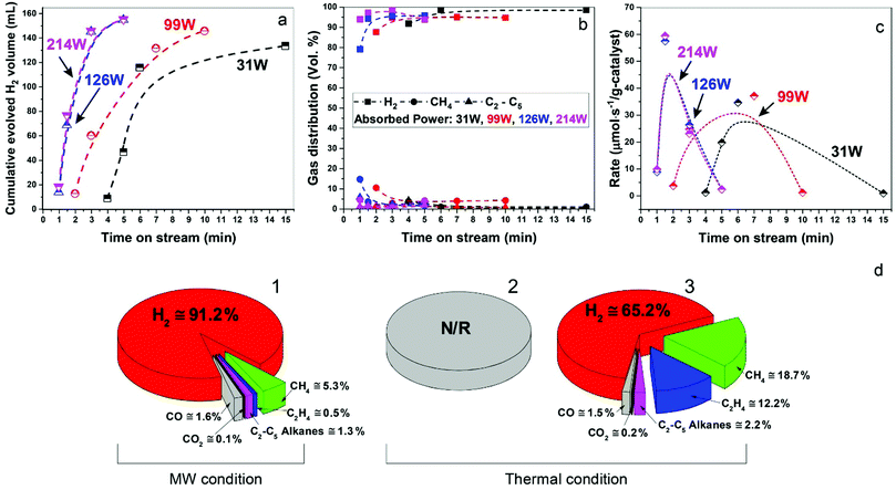
In Fig. 3a–c, we show data for ‘time-on-stream’ experiments for diesel fuel on a Fe/SiC catalyst initiated under various microwave absorbed powers. It can be seen that whilst hydrogen production rates are strongly dependent upon the incident microwave power levels, hydrogen selectivity itself is not significantly affected by the levels of incident and absorbed microwave power.
Importantly, as with our earlier studies on wax,19 we note that hydrogen evolution also ceases instantly upon the cessation of microwave irradiation. This is in direct contrast to any conventional thermal heating process, where hydrogen evolution continues to proceed even upon the loss of input (external) heat, as both the catalyst particle and the surrounding “bath” of hydrocarbons slowly cool (Fig. 1). Further studies are underway to investigate this important aspect relating to the electromagnetic microwave energy-induced catalyst metal particle–host hydrocarbon ‘‘bath’’ interaction. This is a clear illustration that electromagnetic energy from the incident microwaves is being directly – and highly effectively – transmitted to the metal catalyst particles themselves to catalyse hydrogen production from the fossil fuels.
As shown in Fig. 3d, the microwave-initiated catalytic dehydrogenation of diesel produced different levels both of catalytic activity and the (resulting) product selectivities, as compared to the conventional thermal catalytic processes. A stand-out observation, actually common to all the various hydrocarbon feedstocks, is the recurring high selectivity to hydrogen formation under the microwave-initiated catalytic process, as compared to the conventional thermal catalytic dehydrogenation process. We attribute this behaviour once again to the incident microwave electromagnetic energy being selectively, effectively and preferentially absorbed by the iron fine particles as the active catalytic centre, with only modest heating of the surrounding bulk hydrocarbon fuel by the incoming microwaves. Thus, pure hydrogen is rapidly extracted from the reactant hydrocarbon fuel through the microwave-initiated catalytic reaction at the iron particle surface; this process occurring faster than either the vaporisation of fuel from the heated particle (in our trickle-feed catalyst bed configuration) or the alternative catalytic-cracking to various hydrocarbons (Fig. 1). In contrast, for the corresponding thermal process (Fig. 3d2), rapid vaporisation of the fuel at elevated temperatures predominates before significant catalytic dehydrogenation can occur, with attendant changes also in the resulting product distribution.
In the absence of microwave-initiation of the catalytic process, the hydrogen concentration was significantly decreased when we preheated the catalyst bed (using an electrical furnace) before carefully introducing the diesel fuel (Fig. 3d3); under these conditions, higher concentrations of light alkane products were obtained in the evolved gases, suggesting that (conventional) thermal cracking was dominant.22,23
In contrast, under microwave initiation, the iron particles themselves are rapidly heated to initiate the catalytic dehydrogenation process. This probably arises since a conventional thermally-heated catalytic process produces a multitude of active constituents at the high temperatures of the catalytic process (Fig. 1) – these active constituents would include the metal catalyst particles, the support material itself and the hydrocarbon bath itself.
In view of the complex nature of the microwave-initiated heterogeneous catalytic processes involved in this process, at present it is not possible to formulate a complete detailed mechanism for the highly preferential dehydrogenation we observe. Further detailed studies that take into account the nature, and amount, of selective microwave absorption during catalytic turnover are now planned. However, what is clear is that this heterogeneous system – hydrocarbon fuel + catalyst – under microwave initiation can lead to non-equilibrium conditions at the catalyst that appear to accelerate specific endothermic reactions. In particular, the primary products of the catalytic transformation on the (microwave) heated metal particle surface are quenched rapidly as they diffuse away from the metal particle and move into the bulk of the colder hydrocarbon reaction mixture surrounding the catalyst, (of course, that hydrocarbon fluid does not itself significantly absorb the microwave energy). It may be the case that products such as hydrogen, atypical product for the conventional (uniform) heating of the catalytic system, can be formed and stabilised. Furthermore, hydrogen corresponds to the stabilised product that very high “local” temperatures – i.e. at the catalyst particle itself – can be rapidly generated under non-equilibrium pyrolytic conditions.
Post-reaction analysis of catalysts
At the completion of our microwave initiation experiments, high-resolution transmission electron microscopy (HRTEM) revealed turbostratic graphitic sheets and multi-walled carbon nanotubes (MWCNTs) that encapsulate both iron and iron carbide nanoparticles. The generation of iron carbide suggested that the supported iron particles react with the hydrocarbon during the catalytic reactions under microwave initiation (Fig. 4b and c).The presence of Fe3O4 has also been detected by HRTEM (Fig. 4a) in the unreacted catalyst and is considered to form due to the aerial oxidation of nanoparticulate iron. Energy-dispersive X-ray spectroscopy (EDX) mapping also detected the presence of oxygen on some of the iron particle surfaces which could be the source of CO (Fig. S1, ESI†).
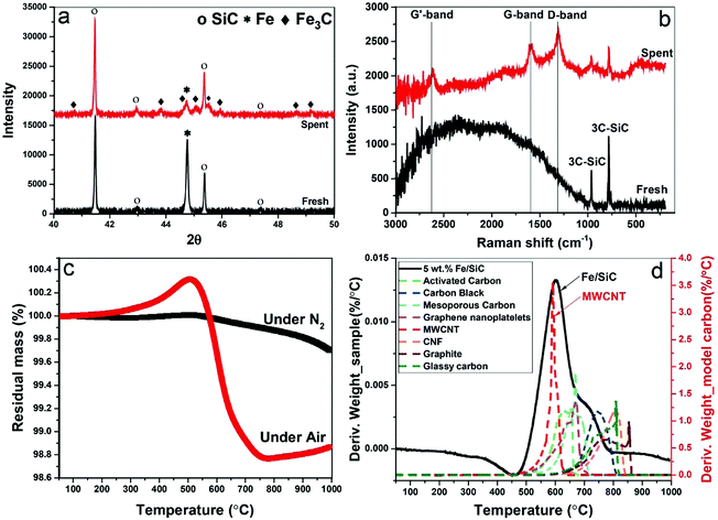
The formation of iron carbide was also confirmed by X-ray diffraction (XRD) (Fig. 5a). The peak of iron at 44.79° was detected in the fresh sample but disappeared after microwave treatment with which the diffraction peaks of Fe3C was detected in spent samples at the angles (2θ) of 42.92°, 43.82°, 44.72°, 45.04°, 45.9°, and 49.18°.24 Although, no single diffraction peak of carbon was observed in the spent samples, the formation of graphitic carbon and MWCNTs were evident in our HRTEM studies, as well as the Raman spectra, thermogravimetric analysis (TGA) and scanning electron microscope (SEM) (Fig. S2, ESI†).
Raman spectroscopy reveals characteristic D-band, G-band and G′-band of solid carbon (Fig. 5b) in the spent samples. The D-band observed at around wavelength of 1350 cm−1 is characteristic of amorphous or disordered carbon, while the peak at about 1580 cm−1 (G-band) is ascribed to the vibration of sp2-bonded carbon atoms in a graphite layer corresponding to ordered graphite carbons. The G′-band peak at around 2700 cm−1 is associated with the process of two-photon elastic scattering. The peak intensity ratio of IG/ID and IG′/IG of the spent samples are 0.9 and 0.79, respectively, which suggests the deposited carbon has high carbon nanotubes purity.25 This is also evident in our thermogravimetric analysis (TGA) when compared to various model carbons.
The TGA study under N2 atmosphere shows that no intermediates and/or unreacted feedstock were stored in the spent catalysts (Fig. 5c). The following temperature programmed oxidation (TPO) illustrated the yield of carbon after single batch test, which is about 2 wt%. The catalysts can be effectively used for several catalytic cycles through successive additions of fresh feedstock to the reactor system with the growing carbon instantly accumulated on the metal catalyst particle. The oxidation temperature of resulting carbon was referenced to a range of selected model sp2-bonded carbons (Fig. 5d), including activated carbons (ACs), carbon black (CB), graphite, carbon nanofibers (CNFs) and MWCNTs etc. Among these 8 different carbons, the resulting carbon in the spent catalyst has a similar oxidation temperature to MWCNTs at about 593 °C, which also strongly suggests that the majority of carbon produced through this catalytic dehydrogenation is carbon nanotubes. A secondary peak at ca. 700 °C is considered caused by the oxidation of other types of carbon with high content of structural defects.
The storage and possible utilisation of carbon by-product residues
It is important to compare the present approach with conventional carbon capture and storage (CCS) to prevent increasing CO2 levels in atmosphere by capturing and storing gaseous CO2 under the ocean or into geologic formations (e.g. depleted oil and gas reservoirs, etc.).26–28 CCS remains an expensive and ecologically uncertain solution; the capture, transportation and disposal of CO2 remain costly and the potential hazards associated with underground and oceanic CO2 sequestration are still uncertain.26,29,30 Thus, an alternative route for CCS, could be achieved by extracting and storing solid carbon itself from our microwave-initiated catalytic dehydrogenation of fossil fuels, whilst also providing the formed hydrogen to be utilised as clean fuel. As Muradov26 has noted, it is more attractive – from both a technical and indeed an ecological (and societal) – viewpoint to store elemental carbon underground rather than gaseous CO2. To contrast and reflect on the levels of both capture processes; taking diesel as an example, the complete dehydrogenation of 1 kg diesel to hydrogen and carbon would generate around 0.961 kg of elemental carbon. The complete aerial combustion of this same 1 kg of diesel will lead to 3.155 kg of CO2 emission, corresponding to 1.606 m3 of CO2 released to the atmosphere.Efficient catalytic dehydrogenation of the various hydrocarbon sources and fuels clearly leads to the production of a pure by-product, elemental, solid carbon. We note also that the resulting carbon nanotubes produced from this process potentially have high value whilst the iron catalysts are both inexpensive and abundant. The recycling of the pure co-product carbon for other applications is attractive and a key point that has been outlined elsewhere by Muradov, Steinberg, and co-workers.26,31,32 In Fig. 6, we identify potential routes for the solid carbon product generated by microwave-initiated fossil fuels dehydrogenation. One possible application is that the carbon can be used as catalysts for other processes (e.g. electrochemistry) and carbon electrodes for industrial scale electrolysis. In addition, the majority of carbon produced during the dehydrogenation process are CNT's, of potentially high-value. Deng et al. previously synthesised a catalyst with iron nanoparticles inside the CNTs,33 that exhibits a high activity and stability towards oxygen reduction reaction (ORR) in polymer electrolyte membrane fuel cells (PEMFC). Moreover, it has been estimated that the direct carbon utilisation by other areas (e.g. building construction materials and soil amendment) could potentially consume very considerable amounts of the solid carbon by-product.26 Besides, we note that the carbon has a great host of uses such as manufacturing graphite anodes for the isolation of metals like aluminium, as well as producing syngas for valuable chemicals’ synthesis.
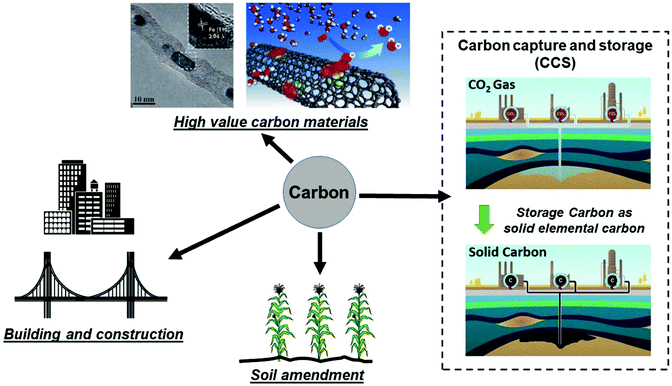 | ||
| Fig. 6 Representative storage and various utilisation routes for elemental carbon produced from fossil fuel dehydrogenation, where the hydrogen component of fossil fuels is used as a clean fuel and the remaining solid carbon ends up as either stored underground or other uses. (Modified from ref. 26, 30 and 33.) | ||
The regeneration of metal catalysts and carbon by-product conversion
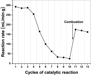
In Fig. 7, we present the results of a study to regenerate the iron catalyst activity by removing, through combustion, the build-up of carbon residues following a successive of 10 catalytic cycles. The high initial dehydrogenation rate in catalytic activity gradually diminished and finally transitioned to at a low quasi-steady reaction rate. Following removal of elemental carbon on the catalyst particle surface by simple combustion after 10 cycles, the catalyst's activity was recovered and remained for several cycles of dehydrogenation. We note that the activity of the catalyst was not fully recovered because of iron oxide presented after the combustion process.Furthermore, the metal catalysts and indeed the carbon co-product could also be regenerated through gasification with steam to produce H2 and CO. Then the syngas can be either separated or used directly as a Fischer–Tropsch feedstock and subsequently recycled back to high-value hydrocarbons. In this process, more H2 can be produced and importantly, the carbon product itself could now also act as a “microwave receptor’’ catalyst under microwave irradiation.
Net Energy Balance considerations
Turning to the important consideration of energy balance, the microwave system is a rather complex system, particularly when combined with absorption of a dispersed heterogeneous catalysis in a host hydrocarbon medium. Thus, it is difficult to accurately evaluate the efficiency, particularly in a general-use laboratory microwave cavity device without, for example, impedance matching. Notwithstanding, we attempt to begin to look at the ultimate effectiveness of these hydrogen production processes through evaluation of the “Net Energy Balance (NEB”).19,34In its simplest and most transparent form, the NEB simply reflects the ratio of energy derived (i.e. the Energy Out) from the exiting chemical feedstock (here taken solely as hydrogen and neglecting the chemical energy of co-product solid carbon) to the energy invested (i.e. the Energy In) for the particular process.
We take the NEB here to be the ratio of chemical energy (Energy Out) as the enthalpy of combustion of the hydrogen produced from the fossil fuels, to the energy invested (Energy In) as the electricity power consumption in both the microwave system or the electric furnace:
As a preliminary investigation, we also carried out a detailed thermodynamic analysis on the process of the complete dehydrogenation of diesel as a representative hydrocarbon fuel. The theoretical minimum energy required for complete dehydrogenation of diesel to elemental hydrogen and solid carbon is ∼1.4 MJ per kg-diesel and the produced hydrogen has an enthalpy of combustion of ∼18.25 MJ per kg-diesel (Table S2, ESI†). Thus, a very large positive Net Energy Balance can, in principle, be obtained, given a high selectivity in the dehydrogenation process.
However, the NEB ratio is of course critically dependent on the absorbed microwave power (i.e. the delivered power), Thus, the delivery of microwave power to the entire catalytic system and the subsequent conversion need to be further optimised and integrated in order to achieve these theoretical values.
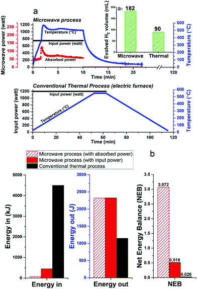
Unfortunately, at present nearly 75–90% of the microwave energy used in our small-scale experimental laboratory configuration is lost (Fig. 8a and Fig. S3, ESI†), quite simply because the high-power microwave device is presently configured only for our very small sample volume (ca. 1.13 cm3). However, future larger-scale microwave systems would be designed to achieve 99.9% efficient absorbed power and, most important, renewable sources of primary electricity can be used for the generation of microwaves.35–37 Such technology optimisation can lead to significant energy savings towards this process.
Notwithstanding these present laboratory limitations, we can show that the microwave-initiated process is energy efficient, as compared to conventional thermal catalytic processes (Fig. 8b; full details given in Table S3, ESI†). In this comparison, the corresponding conventional thermal catalytic dehydrogenation process was carried out in an electric furnace. We controlled both processes (microwave + thermal) at a comparable reaction temperature with close to identical amounts of diesel input.
Fig. 8a presents the profile of the two processes in terms of the electric input power and temperature. We note again the very short times for hydrogen evolution under microwave-initiation,19 and this highly effective energy transfer process in comparison to the conventional thermal process for heating catalyst particles and the subsequent dehydrogenation process is at the very heart of the enhanced efficiencies.
In relation to the Net Energy Balance (NEB) considerations, the Energy Out is taken as the enthalpy of combustion of the produced hydrogen from the two dehydrogenation processes, whereas, the Energy In refers to the electricity power consumption of the two different systems, which are calculated from their tabulated electric power rating and the experiment time of two processes. In the microwave-initiated process, we have also presented the delivered (absorbed) microwave power to give an outlook for a future optimised microwave system (Fig. 8b).
It was found that the Net Energy Balance of both microwave and thermal processes were very low at the laboratory scale set-up, typically, less than 3%. However, the microwave initiation points to about 20 times higher NEB values as compared to values obtained under conventional thermal process, when one takes into account the time axis of both processes (Fig. 8a).
The superior Net Energy Balance of using microwaves for hydrogen production is due primarily to the rapid heating and the high activity and selectivity of the fine iron catalyst. Again, it should be noted that in our laboratory configuration, only about 17% of microwave input power was absorbed at the catalyst system used for the dehydrogenation process. The Net Energy Balance of the microwave could reach nearly 120 times higher than the thermal process if one considers only the level of directly absorbed microwave power.
Fossil fuels as hydrogen storage materials
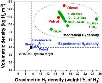
Fossil hydrocarbon fuels are themselves excellent natural hydrogen storage materials since they potentially exceed the targets of H2 gravimetric and volumetric densities set by the U.S. DoE.15,38 Our results for the microwave-initiated iron-catalysed dehydrogenation of diesel, has shown H2 gravimetric and volumetric densities of 8.6 kg-H2 per kg and 71 kg-H2 per m3, respectively, exceeding the target of 7.5 kg-H2/kg and 70 kg-H2/m3 set by the U.S. DoE (Fig. 9). Microwave-initiated catalytic dehydrogenation of fossil fuels could therefore become potentially viable for fuel cell vehicles because of three attractive features: first; the rapid production of high-purity hydrogen, highlighted in this study; second; the necessity for only a small-scale microwave source and reactor system easily attainable for modern high power, small microwave devices for either localized or distributed distribution; and third; the well-established distribution infrastructure for fossil fuels. Clearly, further scale-up and other studies are needed in both engineering aspects and the optimisation of the entire catalytic process for future applications. Nevertheless, this work clearly highlights the possible advantages of microwave to assist in the instant generation of high purity hydrogen, not only from untreated petroleum products (crude oil etc.) but also from a variety of fossil-derived liquid fuels.Concluding remarks
The work described here illustrates that the microwave-initiated catalytic dehydrogenation of naturally-occurring, crude oils, and the resulting hydrocarbon fossil fuels allows for the rapid production of large volumes of hydrogen using inexpensive and abundant fine iron catalysts.Through their aerial combustion, fossil fuels produce potentially climate-damaging CO2. Alternatively, these same fossil fuels could be used to rapidly produce clean, carbon-free hydrogen through microwave-initiated catalytic dehydrogenation. Based on the advances reported here, it is our belief that the undoubted attributes of fossil fuels, being relatively inexpensive, widely available and readily adaptable to applications large and small, simple and complex, can significantly catalyse the staged transition to a hydrogen-based, sustainable energy economy.
A new scientific and technological era of “Fossil fuel decarbonisation” can therefore arise where we will not destroy naturally-occurring fossil fuels by combustion – fire-conflagration1 – with attendant CO2 emissions, but rather utilise these natural resources to produce clean, carbon-free hydrogen. Thus, through this process, carbonaceous fossil fuels are thereby transformed from carbon-rich to hydrogen-rich fuels for our future energy.
Experimental
Preparation of catalysts
The catalysts used in this study were iron based catalysts and prepared by an incipient wetness impregnation method. Metal nitrates, Fe(NO3)3·9H2O (iron(III) nitrate nonahydrate, Sigma-Aldrich), was used as catalyst precursors whilst SiC (silicon carbide, Fisher Scientific) and AC (activated carbon, Sigma-Aldrich) were used as supports. The supports were mixed with an aqueous solution of iron nitrate, the concentration of which was calculated to produce a desired Fe loading. The mixture was then stirred at 150 °C on a magnetic hot plate for 3 h until it became a slurry, which was moved into the drying oven and left overnight. The resulting solid mixtures were calcined in a furnace at 350 °C for 3 h. Finally, the active catalysts were obtained by a reduction process in 10% H2/Ar gases at 800 °C for 6 h.Characterisation of catalysts
The catalysts were carefully characterised before and after experiments by powder X-ray diffraction (XRD, PANalytical X’Pert PRO diffractometer), thermogravimetric analysis (TGA, TA Instrument, SDT Q-600), Laser-Raman spectroscopy (PerkinElmer RamanStationTM 400F spectrometer), scanning electron microscope (SEM, JEOL 840F) and Energy-dispersive X-ray spectroscopy (EDX, ZEISS MERLIN).The powder X-ray diffraction (XRD) used a Cu Kα X-ray source (45 kV, 40 mA) on a PANalytical X’Pert PRO diffractometer. The scanning range (in 2θ) in this study was 10° to 80°. Thermogravimetric analysis (TGA) was used to characterise the feedstocks remaining and the resulting carbon residue in spent samples. The TGA was first carried out in an N2 atmosphere to measure the remaining fuel in spent catalysts, then a temperature programmed oxidation (TPO) was carried out under air. The resulting carbon residues were also investigated via Laser-Raman spectroscopy, with laser excitation at 785 nm. The scanning electron microscope (SEM, JEOL 840F) was used to characterise the surface morphology of the Fe/SiC catalysts before and after microwave initiation. The surface elemental was analysed by Energy-dispersive X-ray spectroscopy (EDX, ZEISS MERLIN).
The Fe/SiC catalysts were also examined by high-resolution transmission electron microscopy (HRTEM) before and after microwave treatment using JEM-3000F microscope (300 kV). The catalyst powder was dispersed in ethanol in an ultra-sonic bath for 15 min. The solution was then drop cast onto a 300-mesh copper TEM holey carbon grid on a filter paper and allowed to evaporate. Scale bars of all the TEM images were calibrated using an oriented gold crystal grid.
Dehydrogenation process under microwave initiation
The experimental setup is shown in Fig. 1b. Microwave system consists of a microwave generation system, a purpose-built microwave cavity and a control system.The microwave heating system chain prior to the applicator consisted of a power generator, microwave head, microwave circulator, dummy load, microwave power meters and tuneable waveguide sections (Sairem Ltd). The system was computer controlled using the Labview software. The applicator section was fabricated in the Inorganic Chemistry Laboratory at the University of Oxford. The operating frequency was 2450 MHz (±25 MHz) from 10% to 100% of nominal power. The maximum output power was 2000 W with 1% stability from 10% to 100% of maximum power after thirty minutes on. The microwave source is a magnetron with a ripple rate of <1% RMS from 10% to 100%. The power rise time is about 100 μs. The power generator is a resonant switching converter with frequencies of 30 kHz up to 80 kHz and an efficiency of 93% at nominal power. The power supply and microwave head are both water and air cooled. The microwave output is via WR 340 waveguides. The generator is controlled remotely via an RS232 MODBUS gateway using the Labview software. The reflected power R, was measured by a crystal detector mounted onto the isolator load, from which we determine the power absorbed by the sample, P. If the power transmitted to the sample is W, then P = W − R − X, where X is the microwave power being dissipated in the cavity walls and/or being radiated. The applicator used was a TM010 resonant cavity to enable a well-characterized field distribution and high nominal field strength. Thus, in this work we investigate electric field driven processes, with a high electric energy density in the sample region.19,20
The sample temperature was measured using an infrared (IR) pyrometer, which was also used to control the power to the generator. The pyrometer was positioned horizontally to face a side hole in the microwave cavity. The IR thermometer can only measure the external surface temperature of the catalyst. During the microwave experiment a temperature (T) versus time (t) of reaction profile was recorded. Typically, the power that was delivered to the sample by the microwave radiation and which was dissipated over the sample volume was between 20 W and 200 W.19,20
Typically, about 1.13 cm3 of the catalyst was first placed in a quartz tube (inner diameter 6 mm, outer diameter 9 mm) and the height of the catalyst bed exposed to the axially polarised (TM010) uniform electric fields was 4 cm. Fuel (about 30 wt%–60 wt% of sample) was then injected into tube and 5–10 minutes was given until the aqueous hydrocarbons were well dispersed into catalysts bed. Then, the filled tube was placed axially in the centre of the TM010 microwave cavity to minimise depolarisation effects under microwave radiation. Before starting microwave irradiation, the samples were purged with an Ar flow rate of 1.67 mL s−1 for a period of 15 minutes. Then, the sample was irradiated with microwaves for 10–30 min at 100 W to 1000 W (typically 750 W). The microwave system is not impedance matched, thus the energy delivered to the sample cavity and the microwave power to which the sample was exposed significantly was less than this value. The generated gases were collected and analysed by Gas Chromatography (GC) using a Perkin-Elmer, Clarus 580 GC. The ‘escaped’ hydrocarbons and the composition of tested fossil fuels were analysed by Gas Chromatograph Mass Spectrometer (GC-MS) using a SHIMADZU, GCMS-QP2010 SE.
Conventional thermal dehydrogenation process
The conventional thermal experiments for diesel dehydrogenation were carried out in an electric furnace for comparison purpose with microwave-initiated experiments. The experimental setup is shown in Fig. 1a. The heating rate of electric furnace used in these experiments were 10 °C min−1.The conventional thermal dehydrogenation of diesel was investigated through two different procedures. For one thermal procedure, a diesel pre-loaded Fe/SiC sample was subjected to a pre-heated furnace (550 °C), while in another procedure, the Fe/SiC catalyst (without fuel) was pre-heated in the furnace to 550 °C and the diesel was then carefully introduced to the hot catalyst bed by a syringe.
Conflicts of interest
There are no conflicts of interest to declare.Acknowledgements
We thank KACST and EPSRC for continued financial support and Dr Afrah Aldawsari and Professor Adrian Porch for their expert assistance in this project. X. Jie gratefully thanks The China Scholarship Council for a scholarship. We thank colleagues at Saudi Aramco for generously providing fossil fuel and crude oil samples.Notes and references
- J. C. Macrae, An Introduction to the study of fuel, Elsevier, Amsterdam, 1966 Search PubMed.
- International Energy Agency, Global Energy & CO2 Status Report, 2017 Search PubMed.
- J. M. Thomas, Nat. Catal., 2018, 1, 2 CrossRef.
- A. Sartbaeva, V. L. Kuznetsov, S. A. Wells and P. P. Edwards, Energy Environ. Sci., 2008, 1, 79–85 RSC.
- S. J. Davis, N. S. Lewis, M. Shaner, S. Aggarwal, D. Arent, I. L. Azevedo, S. M. Benson, T. Bradley, J. Brouwer and Y.-M. Chiang, Science, 2018, 360, eaas9793 CrossRef PubMed.
- P. P. Edwards, V. L. Kuznetsov, W. I. F. David and N. P. Brandon, Energy Policy, 2008, 36, 4356–4362 CrossRef.
- S. A. Wells, A. Sartbaeva, V. L. Kuznetsov and P. P. Edwards, in Encyclopedia of Inorganic and Bioinorganic Chemistry, ed. R. A. Scott, John Wiley & Sons, New Jersey, 2010 Search PubMed.
- J. M. Bockris, Science, 1972, 176, 1323 CrossRef CAS PubMed.
- J. A. Turner, Science, 2004, 305, 972–974 CrossRef CAS PubMed.
- U. Eberle, B. Müller and R. Von Helmolt, Energy Environ. Sci., 2012, 5, 8780–8798 RSC.
- K. Hirose, Philos. Trans. R. Soc., A, 2010, 368, 3365–3377 CrossRef CAS PubMed.
- L. Barreto, A. Makihira and K. Riahi, Int. J. Hydrogen Energy, 2003, 28, 267–284 CrossRef CAS.
- J. Barber, Sustainable Energy Fuels, 2018, 2, 927–935 RSC.
- R. H. Crabtree, Energy Environ. Sci., 2008, 1, 134–138 RSC.
- S. Satyapal, J. Petrovic, C. Read, G. Thomas and G. Ordaz, Catal. Today, 2007, 120, 246–256 CrossRef CAS.
- M. L. Wald, Sci. Am., 2004, 290, 66–73 CrossRef CAS PubMed.
- C. Antonio and R. T. Deam, Phys. Chem. Chem. Phys., 2007, 9, 2976–2982 RSC.
- S. Horikoshi and N. Serpone, Microwaves in Catalysis: Methodology and Applications, Wiley-VCH Verlag GmbH & Co. KGaA, Weinheim, 2016 Search PubMed.
- S. Gonzalez-Cortes, D. Slocombe, T. Xiao, A. Aldawsari, B. Yao, V. Kuznetsov, E. Liberti, A. Kirkland, M. Alkinani, H. Al-Megren, J. M. Thomas and P. P. Edwards, Sci. Rep., 2016, 6, 35315 CrossRef CAS PubMed.
- X. Jie, S. Gonzalez-Cortes, T. Xiao, J. Wang, B. Yao, D. R. Slocombe, H. A. Al-Megren, J. R. Dilworth, J. M. Thomas and P. P. Edwards, Angew. Chem., Int. Ed., 2017, 56, 10170–10173 CrossRef CAS PubMed.
- L. R. Radovic and H. H. Schobert, Energy and fuels in society, McGraw-Hill Education, New York, 1992 Search PubMed.
- B. Greensfelder, H. Voge and G. Good, Ind. Eng. Chem., 1949, 41, 2573–2584 CrossRef CAS.
- R. O. Idem, S. P. Katikaneni and N. N. Bakhshi, Energy Fuels, 1996, 10, 1150–1162 CrossRef CAS.
- L.-S. Fu, J.-T. Jiang, C.-Y. Xu and L. Zhen, CrystEngComm, 2012, 14, 6827–6832 RSC.
- D. Yao, Y. Zhang, P. T. Williams, H. Yang and H. Chen, Appl. Catal., B, 2018, 221, 584–597 CrossRef CAS.
- N. Z. Muradov and T. N. Veziroǧlu, Int. J. Hydrogen Energy, 2005, 30, 225–237 CrossRef CAS.
- M. Bui, C. S. Adjiman, A. Bardow, E. J. Anthony, A. Boston, S. Brown, P. S. Fennell, S. Fuss, A. Galindo and L. A. Hackett, Energy Environ. Sci., 2018, 11, 1062–1176 RSC.
- M. E. Boot-Handford, J. C. Abanades, E. J. Anthony, M. J. Blunt, S. Brandani, N. Mac Dowell, J. R. Fernández, M.-C. Ferrari, R. Gross and J. P. Hallett, Energy Environ. Sci., 2014, 7, 130–189 RSC.
- M. Steinberg, Int. J. Hydrogen Energy, 1999, 24, 771–777 CrossRef CAS.
- Zero Emissions Platform, The Hard Facts behind Carbon Capture and Storage, https://environmentaljusticetv.wordpress.com/2014/10/22/zep-the-hard-facts-behind-carbon-capture-and-storage/.
- M. Steinberg and H. C. Cheng, Int. J. Hydrogen Energy, 1989, 14, 797–820 CrossRef CAS.
- N. Z. Muradov, Int. J. Hydrogen Energy, 1993, 18, 211–215 CrossRef CAS.
- D. Deng, L. Yu, X. Chen, G. Wang, L. Jin, X. Pan, J. Deng, G. Sun and X. Bao, Angew. Chem., Int. Ed., 2013, 52, 371–375 CrossRef CAS PubMed.
- V. G. Gude, P. Patil, E. Martinez-Guerra, S. Deng and N. Nirmalakhandan, Sustainable Chem. Processes, 2013, 1, 1 CrossRef.
- D. M. Pozar, Microwave engineering, John Wiley & Sons, New Jersey, 2009 Search PubMed.
- A. Porch, D. Slocombe, J. Beutler, P. Edwards, A. Aldawsari, T. Xiao, V. Kuznetsov, H. Almegren, S. Aldrees and N. Almaqati, Appl. Petrochem. Res., 2012, 2, 37–44 CrossRef CAS.
- J. Benford, J. A. Swegle and E. Schamiloglu, High power microwaves, CRC Press, Florida, 2015 Search PubMed.
- W. Grochala and P. P. Edwards, Chem. Rev., 2004, 104, 1283–1315 CrossRef CAS PubMed.
Footnote |
| † Electronic supplementary information (ESI) available. See DOI: 10.1039/c8ee02444h |
| This journal is © The Royal Society of Chemistry 2019 |


![[thin space (1/6-em)]](https://www.rsc.org/images/entities/char_2009.gif) wt% Fe/SiC, before; and (b2) after microwave-initiated catalytic reactions, showing characteristic reflections from graphite (002) plane and Fe3C along 〈120〉 zone axis. (c) Low magnification TEM images of produced carbon nanotubes and iron carbide particles in a spent sample.
wt% Fe/SiC, before; and (b2) after microwave-initiated catalytic reactions, showing characteristic reflections from graphite (002) plane and Fe3C along 〈120〉 zone axis. (c) Low magnification TEM images of produced carbon nanotubes and iron carbide particles in a spent sample.