 Open Access Article
Development of P3-K0.69CrO2 as an ultra-high-performance cathode material for K-ion batteries†
Jang-Yeon
Hwang‡
 a,
Jongsoon
Kim‡
 b,
Tae-Yeon
Yu
a,
Seung-Taek
Myung
 b and
Yang-Kook
Sun
 *a
*a
aDepartment of Energy Engineering, Hanyang University, Seoul 04763, South Korea. E-mail: yksun@hanyang.ac.kr
bDepartment of Nanotechnology and Advanced Materials Engineering, Sejong University, Seoul 05006, South Korea
First published on 23rd July 2018
Abstract
Potassium-ion batteries (KIBs) are emerging as a promising energy storage technology because of their low cost and high energy density. However, the large size of K+ ions hinders the reversible electrochemical potassium (de)insertion in the host structure, limiting the selection of suitable electrode materials for KIBs. Herein, we designed and exploited a new layered oxide, P3-type K0.69CrO2 (hereafter denoted as P3-K0.69CrO2), as a high-performance cathode for KIBs for the first time. The proposed P3-K0.69CrO2 cathode was successfully synthesized via an electrochemical ion-exchange route and exhibited the best cycling performance for a KIB cathode material to date. A combination of electrochemical profiles, ex situ X-ray diffraction, and first-principles calculations was used to understand the overall potassium storage mechanism of P3-K0.69CrO2. Based on a reversible phase transition, P3-K0.69CrO2 delivers a high discharge capacity of 100 mA h g−1 and exhibits extremely high cycling stability with ∼65% retention over 1000 cycles at a 1C rate. Moreover, the K-ion hopping into the P3-K0.69CrO2 structure was extremely rapid, resulting in great power capability of up to a 10C rate with a capacity retention of ∼65% (vs. the capacity at 0.1C).
Broader contextRenewable energies play important roles in resolving recent environmental issues associated with global climate change. To date, lithium-ion batteries (LIBs) are the major power sources for portable electronics and are currently used to power vehicles and to store electricity generated from power plants and renewable energy sources. Although the merits of the current LIBs are undeniable, the depletion of lithium sources implies that alternatives to LIBs should be sought to help satisfy the rapidly growing public demand for rechargeable batteries. Because of the low cost and wide distribution of potassium resources, the interest in rechargeable potassium-ion batteries (KIBs) as a substitute for LIBs in particular energy storage applications has surged. Cathode materials for KIBs that are comparable to those of LIBs regarding capacity and retention have been recently investigated. However, more elaboration is required to warrant long term cyclability and power capability. Using the electrochemical ion-exchange method, we successfully synthesized a P3-K0.69CrO2 cathode and proposed its use as a high-performance cathode for KIBs for the first time. The proposed P3-K0.69CrO2 cathode exhibited outstanding cycling stability with ∼65% retention over 1000 cycles and an exceptionally high power capability up to a 10C rate. Experimental and theoretical studies are combined to verify the details of the potassium storage mechanism. We believe that our findings will open up new opportunities for the development of effective cathode materials for potassium storage with high energy density, high power, and low cost. |
Introduction
Environmental issues such as the depletion of fossil fuels and the fine dust pollution problem have driven the demand for ecofriendly and sustainable energy storage systems such as rechargeable batteries.1 Currently, lithium-ion batteries (LIBs) are widely used as the main power source in applications ranging from portable electronics to grid-scale energy storage systems because of their high energy density and satisfactory cycle life. In addition, the recent shift from internal combustion engines to electric vehicles (EVs) has accelerated the demand for high-energy-density LIBs.2 However, the ongoing depletion of the limited global lithium resources needed to meet these demands may restrict the future availability of lithium. Although the merits of current LIBs are undeniable, the depletion of lithium sources implies that alternatives to LIBs should be sought to help satisfy the rapidly growing public demand for rechargeable batteries.3Recently, potassium-ion batteries (KIBs) have attracted particular attention as promising alternatives to LIBs because of the abundance of global potassium resources and the lower standard redox potential of potassium compared with that of other metallic elements (E°(Li/Li+): −3.04 V; E°(K/K+): −2.93 V; E°(Na/Na+): −2.71 V; E°(Mg/Mg2+): −2.27 V vs. the standard hydrogen redox potential).4 Moreover, the potassium intercalation chemistry of KIBs has been demonstrated to be comparable to the lithium intercalation chemistry of LIBs; thus, the established system for LIBs can be more smoothly transferred to KIBs than to other rechargeable batteries.5,6 Reflecting on these situations, several positive and negative electrodes were introduced.5–10
Layered structured cathodes have been intensively studied as promising cathode materials for potassium-ion batteries because of their high gravimetric energy density, which is attributed to their small molar mass and large two-dimensional alkali-ion diffusion paths.11–14 However, the larger size of K+ ions (∼1.38 Å) relative to Li+ ions (∼0.76 Å) and Na+ ions (∼1.02 Å) makes it difficult to identify high-energy and high-rate intercalation cathode materials. Although a few initial studies have demonstrated the electrochemically reversible potassium (de)intercalation reaction, the cycling stability and rate capability were unsatisfactory for efficient battery applications.10,12 Therefore, the development of efficient cathode materials that can accommodate repeated extraction/insertion of large K+ ions without sacrificing the structural stability remains a critical issue for the practical application of KIBs.
Accordingly, we aimed to develop a Cr-based layered oxide as an efficient K intercalation host cathode, as prominent research groups have demonstrated the feasibility of reversible and fast Na-ion diffusion in a layered structured O3-NaCrO2 cathode despite a large ionic size of Na (∼1.02 Å).15,16 Recently, it was reported that K ions can be intercalated into the O3-NaCrO2 structure.14 However, in this case, because of the considerable number of Na+ ions already present in the crystal structure, only a small number of K+ ions could be intercalated via the Na/K dual intercalation reaction. By forming the NaxKyCrO2 structure, this cathode experienced complicated phase transition behavior during the potassiation–depotassiation process; this leads to structural instability and limits long-term cycling stability. This behavior is usually observed in LIBs and SIBs.17,18 Therefore, structural optimization to avoid biphasic formation and a better understanding of the reaction mechanisms during the extraction/insertion of K ions are needed to develop an efficient Cr-based layered oxide cathode.
Herein, we optimized the structure of a Cr-based cathode material that can produce a reversible intercalation–deintercalation reaction and achieve superior potassium storage performance. Using the electrochemical ion-exchange method, we successfully synthesized a pure P3-K0.69CrO2 from O3-NaCrO2 and proposed its use as a high-performance cathode for KIBs for the first time. Despite the large changes in the c lattice parameter (∼1 Å), a reversible transition for the P3-K0.69CrO2 cathode was unexpectedly observed in the voltage range of 1.5–3.8 V (vs. K+/K). This behavior differs from that observed for the previously reported K-based layered-structured cathode materials. Surprisingly, the proposed P3-K0.69CrO2 cathode exhibited a high reversible capacity of 100 mA h g−1 at a 0.1C rate and displayed extremely high cycling stability with ∼65% retention over 1000 cycles (vs. the initial capacity) at a current density of 1C, which is the best cycling performance reported to date for a cathode material for KIBs. Moreover, P3-K0.69CrO2 displayed excellent power capability with 65% capacity retention at 10C (vs. the initial capacity at 0.1C). Theoretical studies using first-principles calculations provided further insight into the superior K-storage performance of P3-K0.69CrO2.
Results and discussion
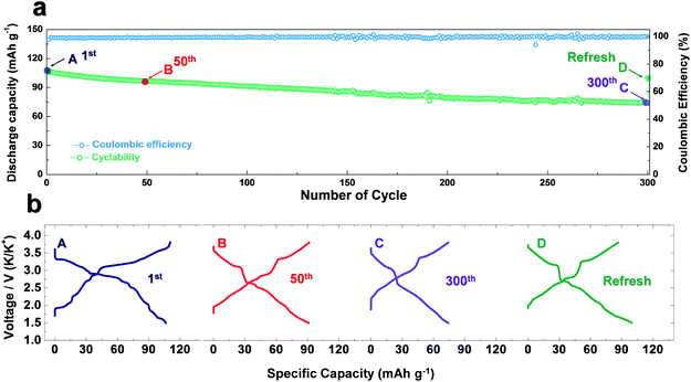
The preparation of P3-KxCrO2 using the electrochemical ion-exchange process in this work was motivated by the difficulty of the synthesis of pure P3-KxCrO2 using the typical solid-state method. As observed in the X-ray diffraction (XRD) patterns in Fig. S1 (ESI†), none of the KxCrO2 (x = 0.3, 0.7, 1.0, and 1.5) samples synthesized using the solid-state method were classified as a general layered structure. Thus, to obtain a highly pure P3-KxCrO2 cathode, a non-aqueous-based electrochemically driven ion-exchange process was used to transform the O3 phase NaCrO2 (O3-NaCrO2) into a P3-KxCrO2 cathode (Fig. 1). Once the highly crystalline O3-NaCrO2 was prepared using a solid-state method (Fig. S2, ESI†), electrochemical Na+/K+ ion-exchange was performed under K-metal|0.5 M KPF6 in an ethylene carbonate (EC)![[thin space (1/6-em)]](https://www.rsc.org/images/entities/char_2009.gif) :
:![[thin space (1/6-em)]](https://www.rsc.org/images/entities/char_2009.gif) diethyl carbonate (DEC) = 1
diethyl carbonate (DEC) = 1![[thin space (1/6-em)]](https://www.rsc.org/images/entities/char_2009.gif) :
:![[thin space (1/6-em)]](https://www.rsc.org/images/entities/char_2009.gif) 1 (v/v)|O3-NaCrO2 cell in the voltage range of 1.5–3.8 V (Fig. 1a) during 300 cycles. During the first desodiation process, ∼0.5 mol Na ions were extracted from the O3-NaCrO2 structure, corresponding to an initial charge capacity of ∼125 mA h g−1 (Fig. S3, ESI†). We only extracted the 0.5 mol Na ions from the NaCrO2 structure because when a large amount of Na ions (above 0.5 mol Na) was extracted from the layered structures by charging over 3.8 V, NaCrO2 experienced irreversible structural transitions, resulting a severe structural degradation.19 During the subsequent discharge process (potassiation) to 1.5 V, the K+ ions were progressively intercalated with several voltage steps and reached a discharge capacity of 112 mA h g−1 (Fig. S4, ESI†). The multiple voltage steps observed in discharge potential profile (Fig. S4a, ESI†) and dQdV−1 curves (Fig. S4b, ESI†) during the first potassiation process clearly demonstrate the complicated phase transition behavior of the Na/K dual-intercalation reaction. We also confirm that the new diffraction lines (marked by blue arrows) in the XRD pattern (Fig. S5, ESI†) can be assigned to a K-rich P3-type layered phase, which is in good agreement with the P3-type layered structure in the previous report.11
1 (v/v)|O3-NaCrO2 cell in the voltage range of 1.5–3.8 V (Fig. 1a) during 300 cycles. During the first desodiation process, ∼0.5 mol Na ions were extracted from the O3-NaCrO2 structure, corresponding to an initial charge capacity of ∼125 mA h g−1 (Fig. S3, ESI†). We only extracted the 0.5 mol Na ions from the NaCrO2 structure because when a large amount of Na ions (above 0.5 mol Na) was extracted from the layered structures by charging over 3.8 V, NaCrO2 experienced irreversible structural transitions, resulting a severe structural degradation.19 During the subsequent discharge process (potassiation) to 1.5 V, the K+ ions were progressively intercalated with several voltage steps and reached a discharge capacity of 112 mA h g−1 (Fig. S4, ESI†). The multiple voltage steps observed in discharge potential profile (Fig. S4a, ESI†) and dQdV−1 curves (Fig. S4b, ESI†) during the first potassiation process clearly demonstrate the complicated phase transition behavior of the Na/K dual-intercalation reaction. We also confirm that the new diffraction lines (marked by blue arrows) in the XRD pattern (Fig. S5, ESI†) can be assigned to a K-rich P3-type layered phase, which is in good agreement with the P3-type layered structure in the previous report.11
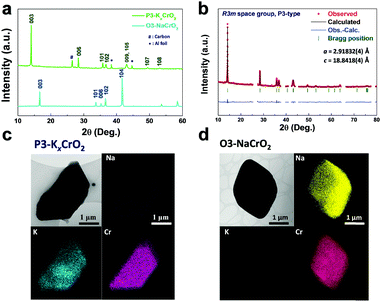
Following several charge–discharge processes (50 cycles), multiple voltage steps gradually disappeared from the voltage profiles, indicating that the Na ions were continuously replaced by the K ions in the host structure (Fig. 1b). Although the electrochemical ion-exchange progressed under 3.9 V in order to avoid electrolyte decomposition, the relatively low Coulombic efficiency was observed; this indicates that not only the K ions but also the residual Na ions in the structure have been gradually extracted during the charging process (in Fig. S6, ESI†). Compared to the ex situ XRD patterns of the electrode in the initial discharge state (potassiation state), a set of new (003) and (006) peaks corresponding to hexagonal P3-KxCrO2 appeared for the 50th-cycled electrode,11 with the hexagonal (003) and (104) peaks originating from the NaxCrO2 structure (in Fig. S7, ESI†).14,15 This indicated that the electrochemical Na+/K+ ion exchange was not yet completed after 50 cycles. To obtain pure P3-KxCrO2, therefore, a further ion-exchange process was conducted under the same conditions. Unfortunately, the slow ion-exchange process under several cycles after removal of only 0.5 mol Na ions from NaCrO2 is inevitable to synthesize the P3-phase layered KxCrO2 without Na content; because the intercalation of the K ion into the Na-based layered structure is more difficult than that of Na-ion intercalation due to the bigger ionic size of the K ion (Na+: 1.02 Å vs. K+: 1.38 Å). In addition, another possible reason for the slow electrochemical ion-exchange reaction could be attributed to the relatively lower solvation energy of the Na ion than that of the K ion in the organic electrolyte solution.20 After 300 cycles, the multiple voltage steps obviously disappeared from the voltage profiles (Fig. 1b). Finally, the Coulombic efficiency reached almost 100% at the end of the ion-exchange process (270–300 cycles) also providing further evidence for complete ion exchange from Na to K and subsequent stoichiometry change (Fig. S6, ESI†). As observed in the scanning electron microscopy (SEM) images and the corresponding energy-dispersive X-ray spectroscopy (EDX) mapping data in Fig. S8 and Table S1 (ESI†), the precipitated sodium metal on the cycled separators (after 300 cycles) collected from the K|0.5 M KPF6 in the EC![[thin space (1/6-em)]](https://www.rsc.org/images/entities/char_2009.gif) :
:![[thin space (1/6-em)]](https://www.rsc.org/images/entities/char_2009.gif) DEC = 1
DEC = 1![[thin space (1/6-em)]](https://www.rsc.org/images/entities/char_2009.gif) :
:![[thin space (1/6-em)]](https://www.rsc.org/images/entities/char_2009.gif) 1|NaCrO2 cell provides further evidence of successful ion change from Na to K. Moreover, the hexagonal (003) and (104) peaks of the O3-phase NaCrO2 completely disappeared from the ex situ XRD patterns, as shown in Fig. 2a, which clearly demonstrates the successful phase transformation to P3-KxCrO2via the electrochemical ion-exchange process of the Na to K ions. All diffraction was well assigned to a pure P3-type layered phase.11 In addition, the Rietveld refinement of the XRD pattern of the cycled electrode after 300 cycles (in Fig. 2b) was nearly identical to the simulated pattern of the P3-KxCrO2 structure. The elemental analyses by transmission electron microscopy (TEM) and EDX mapping of O3-NaCrO2 and P3-KxCrO2 revealed that the Na+ ions in the O3-NaCrO2 cathode were completely exchanged by the K+ ions (Fig. 2c and d). It was also verified through the TEM-EDX analyses that the atomic ratio of K and Cr at P3-KxCrO2 was ∼0.69
1|NaCrO2 cell provides further evidence of successful ion change from Na to K. Moreover, the hexagonal (003) and (104) peaks of the O3-phase NaCrO2 completely disappeared from the ex situ XRD patterns, as shown in Fig. 2a, which clearly demonstrates the successful phase transformation to P3-KxCrO2via the electrochemical ion-exchange process of the Na to K ions. All diffraction was well assigned to a pure P3-type layered phase.11 In addition, the Rietveld refinement of the XRD pattern of the cycled electrode after 300 cycles (in Fig. 2b) was nearly identical to the simulated pattern of the P3-KxCrO2 structure. The elemental analyses by transmission electron microscopy (TEM) and EDX mapping of O3-NaCrO2 and P3-KxCrO2 revealed that the Na+ ions in the O3-NaCrO2 cathode were completely exchanged by the K+ ions (Fig. 2c and d). It was also verified through the TEM-EDX analyses that the atomic ratio of K and Cr at P3-KxCrO2 was ∼0.69![[thin space (1/6-em)]](https://www.rsc.org/images/entities/char_2009.gif) :
:![[thin space (1/6-em)]](https://www.rsc.org/images/entities/char_2009.gif) 1. These remarkable structural changes from O3-NaCrO2 to the K-ion intercalated structure, P3-KxCrO2, under K-metal|0.5 M KPF6 in the EC
1. These remarkable structural changes from O3-NaCrO2 to the K-ion intercalated structure, P3-KxCrO2, under K-metal|0.5 M KPF6 in the EC![[thin space (1/6-em)]](https://www.rsc.org/images/entities/char_2009.gif) :
:![[thin space (1/6-em)]](https://www.rsc.org/images/entities/char_2009.gif) DEC = 1
DEC = 1![[thin space (1/6-em)]](https://www.rsc.org/images/entities/char_2009.gif) :
:![[thin space (1/6-em)]](https://www.rsc.org/images/entities/char_2009.gif) 1 (v/v)|NaCrO2 cell, have not been previously reported. Hereafter, all the electrochemical tests (galvanostatic intermittent titration technique (GITT), cycling test and power capability test) on the P3-KxCrO2 cathode were performed after refreshing the cell (replacing the electrolyte and K metal), K|0.5 M KPF6 in EC
1 (v/v)|NaCrO2 cell, have not been previously reported. Hereafter, all the electrochemical tests (galvanostatic intermittent titration technique (GITT), cycling test and power capability test) on the P3-KxCrO2 cathode were performed after refreshing the cell (replacing the electrolyte and K metal), K|0.5 M KPF6 in EC![[thin space (1/6-em)]](https://www.rsc.org/images/entities/char_2009.gif) :
:![[thin space (1/6-em)]](https://www.rsc.org/images/entities/char_2009.gif) DEC = 1
DEC = 1![[thin space (1/6-em)]](https://www.rsc.org/images/entities/char_2009.gif) :
:![[thin space (1/6-em)]](https://www.rsc.org/images/entities/char_2009.gif) 1 (v/v)|P3-KxCrO2, because the K metal is largely deteriorated during the long electrochemical ion-exchange process. After refreshing the cell, the P3-KxCrO2 cathode delivered a high discharge capacity of ∼100 mA h g−1 at 0.1C rate (Fig. 1b).
1 (v/v)|P3-KxCrO2, because the K metal is largely deteriorated during the long electrochemical ion-exchange process. After refreshing the cell, the P3-KxCrO2 cathode delivered a high discharge capacity of ∼100 mA h g−1 at 0.1C rate (Fig. 1b).
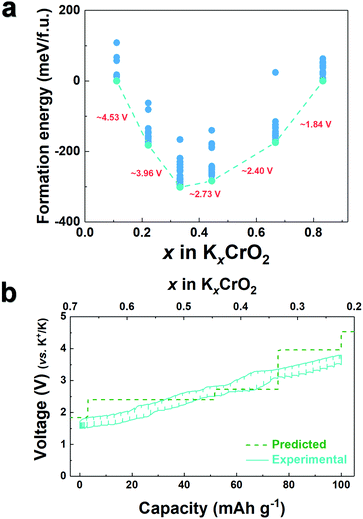
To understand the effect of the K content on the potassium storage mechanism, we computed the formation energies of P3-KxCrO2 as a function of the K content (0.11 ≤ x ≤ 0.83) using first-principles calculations. We considered the P3-phase structure with an ABBCCA oxygen stacking sequence. As shown in Fig. 3a, the computational results indicated that the P3-KxCrO2 cathode reversibly operated with a low formation energy in the voltage range of ∼1.84 to ∼3.96 V (vs. K+/K). Based on the formation energies of the P3-KxCrO2 cathode, we further predicted the theoretical redox potential range of the P3-KxCrO2 cathode, as shown in Fig. 3b. The approximate voltage profile of the P3-KxCrO2 cathode was determined using the following equation:
 | (1) |
The calculated voltage plot with the GITT curves confirmed that the P3-KxCrO2 cathode can accommodate ∼0.69 mol of K ions upon potassiation to 1.5 V by forming the P3-K0.69CrO2 structure, whereas ∼0.47 mol of K ions were extracted following depotassiation to 3.8 V. As a result, the P3-KxCrO2 cathode delivered a specific capacity of ∼100 mA h g−1 with an initial Coulombic efficiency of ∼97%, which corresponds to the reversible intercalation/extraction of ∼0.47 mol K ions into/from P3-KxCrO2 in the voltage range of 1.5–3.8 V. The intercalation of ∼0.69 mol of K ions into P3-KxCrO2 was also comparable with results of the TEM-EDX analyses mentioned above. The formation of P3-K0.69CrO2 after the electrochemical ion-exchange process is reasonable compared with the previously reported P3-type layered oxide materials.8,11 Upon further extraction of K ions beyond ∼0.47 mol, the calculated formation energy of the P3-K0.69CrO2 cathode was less energetically favorable, causing irreversible capacity loss. The poor cycling performance of the P3-K0.69CrO2 cathode in the wide voltage range of 1.5–4.0 V confirms that our computational result is reasonable (Fig. S9, ESI†). In summary, as demonstrated by the computational data and electrochemical results, we can conclude that reversible K (de)intercalation can be achieved in the P3-KxCrO2 cathode for K contents of 0.22< x < 0.69 within the voltage range of 1.5–3.8 V. To obtain further insight into the phase transition with respect to the K content, the crystal structural changes in KxCrO2 as a function of the K content (0.11 ≤ x ≤ 0.83) were further investigated by combining theoretical and experimental studies. The calculated crystal structure and c lattice parameter of KxCrO2 as a function of K content are shown in Fig. 4. When the K ions were extracted from the K layers in the P3-KxCrO2 structure, the c lattice parameter of the P3-KxCrO2 cathode gradually increased because of the repulsion force between the two neighboring oxygen layers (O2−–O2−), as commonly observed in the layered oxide cathode materials in LIBs and SIBs upon deintercalation process.21–23 For 0.44 ≤ x ≤ 0.83, a monotonous increase in the c lattice parameter from 18.48 to 18.83 Å was observed with decreasing K ion content in the P3-KxCrO2 cathode. Notably, an unexpected large increase in the c lattice parameter was observed when the number of K ions in P3-KxCrO2 was less than 0.44 mol, which implies that the unusual phase transition occurred upon potassiation.
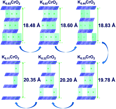 | ||
| Fig. 4 Predicted structural changes of KxCrO2 as a function of the K content (0.11 ≤ x ≤ 0.83) using first-principles calculations. | ||
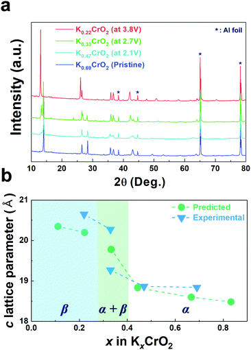
To confirm such predicted computational data, the structural changes of P3-K0.69CrO2 were examined using ex situ XRD analysis during the initial depotassiation at different states of charge (in Fig. 5a). In addition, the predicted values of the c lattice parameter of the KxCrO2 cathode from the first-principles calculations (in Fig. 4) and the experimentally measured values obtained using Rietveld refinement of the ex situ XRD patterns (in Fig. 5a) are plotted in Fig. 5b. The α and β symbols in Fig. 5b indicate a typical P3 phase and a new phase in the P3-type structure, respectively. For 0.44 < x < 0.69, the P3-KxCrO2 cathode retained the typical P3-phase crystal structure and the calculated and experimentally measured c lattice parameter values matched quite well. For x < 0.44 (after charging to 2.7 V (vs. K+/K)), the XRD pattern was similar to that obtained at 2.1 V; however, the relative intensities of the peaks changed considerably at 2θ = 13.2°. This difference suggests that the α-phase underwent a further phase transition to the β phase via a two-phase reaction with an increase of the c lattice parameter (0.28 ≤ x ≤ 0.38 in KxCrO2), which is thought to be due to the large lattice mismatch between the α and β phases. The structure of the β phase was similar to the P3′′ phase structure, which has been speculated to be a highly faulted layer structure with large interslab distances in SIBs.23,24 Unexpectedly, unlike Na-based layered-type oxides, the proposed P3-K0.69CrO2 cathode displayed a reversible phase transformation and superior electrochemical performance.
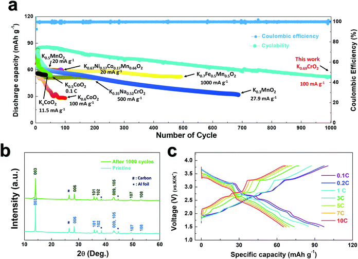
As observed in Fig. 3b, P3-K0.69CrO2 delivered a high reversible capacity of 100 mA h g−1 at 0.1C rate within the voltage range of 1.5–3.8 V. Note that the c lattice parameter of P3-K0.18CrO2 (charged at 3.8 V) is much larger than that of the fully discharged P3-K0.69CrO2, with a difference greater than ∼1 Å. Despite the large lattice parameter changes during charge–discharge process, P3-K0.69CrO2 exhibited outstanding long-term cyclability, providing a capacity retention of ∼65% at 1C after 1000 cycles (Fig. 6a). Surprisingly, even after 1000 cycles, P3-K0.69CrO2 was well maintained its original crystal structure (Fig. 6b); this also emphasizes the excellent structural stability of the Cr-based layered oxide framework against to large size of K+ ions. TEM images in Fig. S10 (ESI†) also show that P3-K0.69CrO2 can survive long-term cycling without serious damage to its morphology. Compared with previously reported layered oxide cathodes,11–14,25–28 the proposed P3-K0.69CrO2 cathode manifested great competitiveness in terms of capacity and long-term cycling stability in KIBs (Fig. 6a). Furthermore, the P3-K0.69CrO2 cathode delivered an unexpectedly high capacity of 65 mA h g−1 at a 10C rate (full charge/discharge in 12 min) and retained 65% of the capacity obtained at a 0.1C rate, indicating that this cathode can sustain respectable power capabilities (Fig. 6c). In KIBs, the power capability of the cathode materials heavily depends on the K+-ion mobility; therefore, investigation of the diffusion of K+ ions in the interlayer is important. The nudged elastic band (NEB) calculation method,29 the use of which has been successfully verified in the study of alkali ion diffusion, was adopted to simulate the activation barrier energy for K+-ion diffusion between K sites in the ab plane (Fig. 7). Along the K–K path at a distance of ∼3.1 Å, the computed diffusion barrier of the K+ ion in P3-K0.69CrO2 was only ∼0.231 eV, which is more highly comparable to the activation barriers than the values of ∼0.2 eV typically observed in commercialized LiCoO2 and LiFePO4 electrodes in LIBs.30,31 Based on the NEB calculations, we can conclude that K-ion hopping into the P3-K0.69CrO2 structure is sufficiently rapid, resulting in the excellent power capability of P3-K0.69CrO2 despite the large size of the K+ ions.
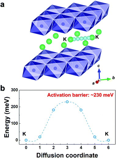 | ||
| Fig. 7 (a) K–K diffusion pathways into the K0.69CrO2 structure. (b) Activation barrier energy for K+ diffusion in K0.69CrO2 obtained using NEB calculations. | ||
Conclusions
In this study, we proposed a novel approach for the development of P3-K0.69CrO2 as an ultra-high-performance cathode material for K-ion batteries. We selected a non-aqueous-based electrochemically driven ion-exchange process to transform O3-NaCrO2 into a pure P3-K0.69CrO2 cathode for the first time. The overall potassium storage mechanism of P3-K0.69CrO2 was investigated using a combination of electrochemical profiles, ex situ X-ray diffraction, and first-principles calculations. Surprisingly, despite the large changes in the c lattice parameter (∼1 Å) as a function of the K content, the reversible phase transformation governed the K+ ion (de)intercalation process in the voltage range of 1.5–3.8 V (vs. K+/K). As a result, the proposed P3-K0.69CrO2 cathode exhibited a high initial capacity of ∼100 mA h g−1 and outstanding cycling stability with ∼65% retention (vs. the initial capacity) over 1000 cycles at 1C. The power capability of the electrode was also excellent; for example, a capacity of 65 mA h g−1 was achieved at a current density of 1000 mA g−1 (10C) (∼65% retention vs. the capacity at 0.1C). This great power capability of P3-K0.69CrO2 was further supported by the low activation energy barrier for K+ migration of ∼0.231 eV into the P3-K0.69CrO2 structure calculated using the NEB method. In this work, we investigated the Cr-based layered oxide as the cathode material, not for commercial application due to toxicity but, for scientific queries to confirm the feasibility of K intercalation. For improved practicality, further studies on the optimization of the electrolyte solution and reducing the slow-ion exchange process are necessary.32,33 We believe that our findings demonstrated herein will open up new opportunities for the development of effective cathode materials for potassium storage with high energy density, high power, and low cost.Conflicts of interest
There are no conflicts to declare.Acknowledgements
This work was supported by a grant from the Human Resources Development program (No. 20154010200840) of the Korea Institute of Energy Technology Evaluation and Planning (KETEP), funded by the Ministry of Trade, Industry and Energy of the Korean government, and the Global Frontier R&D Programme (2013M3A6B1078875) at the Center for Hybrid Interface Materials (HIM), Ministry of Science, ICT & Future Planning.Notes and references
- B. Scrosati, J. Hassoun and Y.-K. Sun, Energy Environ. Sci., 2011, 4, 3284 RSC.
- B. Dunn, H. Kamath and J.-M. Tarascon, Science, 2011, 18, 928 CrossRef PubMed.
- J. W. Choi and D. Aurbach, Nat. Rev. Mater., 2016, 1, 16013 CrossRef.
- J. Paramudita, D. Sehrawat, D. Goonetilleke and N. Sharma, Adv. Energy Mater., 2017, 1602911 CrossRef.
- Q. Zhang, J. Mao, W. K. Pang, T. Zheng, V. Sencadas, Y. Chen, Y. Liu and Z. Guo, Adv. Energy Mater., 2018, 8, 1703288 CrossRef.
- W. Zhang, J. Mao, S. Li, Z. Chen and Z. Guo, J. Am. Chem. Soc., 2017, 139, 3316 CrossRef PubMed.
- W. Zhang, W. K. Pang, V. Sencadas and Z. Guo, Joule, 2018 DOI:10.1016/j.joule.2018.04.022.
- H. Kim, J. C. Kim, M. Bianchini, D.-W. Seo, J. R. Garcia and G. Ceder, Adv. Energy Mater., 2017, 1702384 Search PubMed.
- Z. Jian, W. Luo and X. Ji, J. Am. Chem. Soc., 2015, 137, 11566 CrossRef PubMed.
- X. Wu, D. P. Leonard and X. Ji, Chem. Mater., 2017, 29, 5031 CrossRef.
- Y. Hironaka, K. Kubota and S. Komaba, Chem. Commun., 2017, 53, 3693 RSC.
- H. Kim, D.-H. Seo, J. C. Kim, S.-H. Bo, L. Liu, T. Shi and G. Ceder, Adv. Energy Mater., 2017, 1700098 CrossRef.
- K. Sada, B. Senthilkumar and P. Barpanda, Chem. Commun., 2017, 53, 8588 RSC.
- N. Naveen, W. B. Park, S. Cheol Han, S. P. Singh, Y. H. Jung, D. Ahn, K.-S. Shon and M. Pyo, Chem. Mater., 2018, 30, 2049 CrossRef.
- S. Komaba, C. Take, T. Nakayama, A. Ogata and N. Yabuuchi, Electrochem. Commun., 2010, 12, 355 CrossRef.
- C.-Y. Yu, J.-S. Park, H.-G. Jung, K.-Y. Chung, D. Aurbach, Y.-K. Sun and S.-T. Myung, Energy Environ. Sci., 2015, 8, 2019 RSC.
- S.-T. Myung, F. Maglia, K.-J. Park, C. S. Yoon, P. Lamp, S.-J. Kim and Y.-K. Sun, ACS Energy Lett., 2017, 2, 196 CrossRef.
- J.-Y. Hwang, S.-T. Myung and Y.-K. Sun, Chem. Soc. Rev., 2017, 46, 3529 RSC.
- K. Kubota, I. Ikeuchi, T. Nakayama, C. Takei, N. Yabuuchi, H. Shilba, M. Nakayama and S. Komaba, J. Phys. Chem. C, 2015, 119, 166 CrossRef.
- M. Okoshi, Y. Yamada, S. Komaba, A. Yamada and H. Nakai, J. Electrochem. Soc., 2017, 164, A54 CrossRef.
- Y.-N. Zhou, J. Ma, E. Hu, X. Yu, L. Gu, K.-W. Nam, L. Chen, Z. Wang and X.-Q. Yang, Nat. Commun., 2014, 5, 5381 CrossRef PubMed.
- H.-J. Noh, S. Youn, C. S. Yoon and Y.-K. Sun, J. Power Sources, 2013, 233, 121 CrossRef.
- S. Komaba, N. Yabuuchi, T. Nakayama, A. Ogata, T. Ishikawa and I. Nakai, Inorg. Chem., 2012, 51, 6211 CrossRef PubMed.
- D. D. Yuan, Y. X. Wang, Y. K. Cao, X. P. Ai and H. X. Yang, ACS Appl. Mater. Interfaces, 2015, 7, 8585 CrossRef PubMed.
- C. Vaalma, G. A. Giffin, D. Buchholz and S. Passerini, J. Electrochem. Soc., 2016, 163, A1295 CrossRef.
- X. Wang, X. Xu, C. Niu, J. Meng, M. Huang, X. Liu, Z. Liu and L. Mai, Nano Lett., 2017, 17, 544 CrossRef PubMed.
- H. Kim, D.-H. Seo, J. C. Kim, S.-H. Bo, L. Liu, T. Shi and G. Ceder, Adv. Mater., 2017, 29, 1702480 CrossRef PubMed.
- C. Liu, S. Luo, G. Huang, Z. Wang, A. Hao, Y. Zhai and Z. Wang, Electrochem. Commun., 2017, 82, 150 CrossRef.
- G. Henkelman, J. Chem. Phys., 2000, 113, 9901 CrossRef.
- G. K. P. Dathar, D. Sheppard, K. J. Stevenson and G. Henkelman, Chem. Mater., 2011, 23, 4032 CrossRef.
- K. Hoang and M. D. Johannes, J. Mater. Chem. A, 2014, 2, 5224 RSC.
- E. Markevich, G. Salitra and D. Aurbach, ACS Energy Lett., 2017, 2, 1337 CrossRef.
- X. Bie, K. Kubata, T. Hosaka, K. Chihara and S. Komaba, J. Mater. Chem. A, 2017, 5, 4325 RSC.
Footnotes |
| † Electronic supplementary information (ESI) available. See DOI: 10.1039/c8ee01365a |
| ‡ Jang-Yeon Hwang and Jongsoon Kim equally contributed to this work. |
| This journal is © The Royal Society of Chemistry 2018 |

