 Open Access Article
Creative Commons Attribution 3.0 Unported Licence
Polymeric hole-transport materials with side-chain redox-active groups for perovskite solar cells with good reproducibility†
Rosinda
Fuentes Pineda
 a,
Benjamin R. M.
Lake
 a,
Joel
Troughton
b,
Irene
Sanchez-Molina
c,
Oleg
Chepelin
a,
Saif
Haque
a,
Joel
Troughton
b,
Irene
Sanchez-Molina
c,
Oleg
Chepelin
a,
Saif
Haque
 c,
Trystan
Watson
 *b,
Michael P.
Shaver
 a and
Neil
Robertson
 *a
*a
aEaStCHEM School of Chemistry, The University of Edinburgh, King's Buildings, David Brewster Road, Edinburgh, EH9 3FJ, UK. E-mail: neil.robertson@ed.ac.uk
bSPECIFIC, Swansea University Bay Campus, Fabian Way, Swansea, SA1 8EN, UK. E-mail: T.M.Watson@swansea.ac.uk
cDepartment of Chemistry, Imperial College London, London, SW7 2AZ, UK. E-mail: s.a.haque@imperial.ac.uk
First published on 3rd October 2018
Abstract
Two monomers, M:OO and M:ON, and their corresponding polymers, P:OO and P:ON, were prepared from styrene derivatives N,N-diphenyl-4-vinyl-aniline with different substituents (–OCH3 and –N(CH3)2) in the N-phenyl para positions. The polymers were synthesised and fully characterised to study their function as hole transport materials (HTMs) in perovskite solar cells (PSCs). The thermal, optical and electrochemical properties and performance of these monomers and polymers as HTMs in PSCs were compared in terms of their structure. The polymers form more stable amorphous glassy states and showed higher thermal stability than the monomers. The different substituent in the para position influenced the highest occupied molecular orbital (HOMO) level, altering the oxidation potential. Both monomers and polymers were employed as HTMs in perovskite solar cells with a device configuration FTO/bl-TiO2/mp-TiO2/CH3NH3PbI3/HTM/Au resulting in power conversion efficiencies of 7.48% for M:OO, 5.14% for P:OO, 5.28% for P:ON and 3.52% for M:ON. Although showing comparatively low efficiencies, the polymers showed much superior reproducibility in comparison with Spiro-OMeTAD or the monomers, suggesting further optimisation of polymeric HTMs with redox side groups is warranted.
1 Introduction
In 2009, Miyasaka1 introduced the hybrid organic–inorganic lead halide perovskite as the light-absorbing material in liquid dye-sensitised solar cells (DSSCs) reaching 3.8% power conversion efficiency (PCE). To date, perovskite solar cells (PSCs) have achieved PCEs of over 20%,2,3 opening the possibility to further reduce the cost of solar cell modules. This rapid improvement over a short period is due to the unique properties of the perovskite material including high panchromatic absorption, large carrier diffusion length and low non-radiative recombination.4–6 Based on the perovskite properties, there have been several developments in the cell configuration for perovskite solar cells, yet the most common device structure comprises six mains components: (1) a conductive glass substrate (fluorine tin oxide FTO), (2) a compact TiO2 blocking layer, (3) mesoporous TiO2 (mp-TiO2), (4) a perovskite layer, (5) a hole transport layer and (6) gold as a counter electrode. Furthermore, despite offering high efficiencies, typical perovskite solar cells suffer from stability and durability problems. One promising approach for stabilising PSCs is by modifying the hole transport material (HTM) with an inorganic material,7,8 a small organic molecule9–12 or a polymer. Spiro-OMeTAD13 is the most broadly used HTM in highly efficient solid-state devices. Nevertheless, the lengthy synthesis and expensive purification are barriers to its commercialization. The structure of the hole transport material plays an important role for achieving high efficiency and also helps to protect the sensitive perovskite layer from air and moisture.14 Hence some researchers have focussed on replacing Spiro-OMeTAD with a cheaper material that can give similar efficiencies and improve the stability of these devices. Triarylamine15 derivatives are widely used as hole-transporting materials due to their electron donating and hole transporting capabilities. Polymeric triarylamines may offer improved properties compared to their monomeric or oligomeric derivatives, such as easy film formation to allow for low-cost manufacture of large scale devices. One of the most notable advantages is the higher glass transition temperature (Tg) and amorphous nature of the polymers, suggesting advantageous stability and reproducibility of end devices. Furthermore, the hydrophobic properties of polymers may act as a protecting layer for the perovskite film to external atmosphere or contaminants, which may also enhance the solar cell stability. Previous studies of polymers as promising HTMs in PSCs include: poly(3-hexylthiophene) (P3HT),16 poly[2,6-(4,4-bis-(2-ethylhexyl)-4H-cyclopenta[2,1-b;3,4-b′]dithiophene)-alt-4,7(2,1,3-benzothiadiazole)] (PCPDTBT),17 poly[N-9′-heptadecanyl-2,7-carbazole-alt-5,5-(4′,7′-di-2-thienyl-2′,1′,3′-benzothiadiazole)] (PCDTBT),18 poly-triarylamine (PTAA)19 and others.12In incorporating HTMs into polymers, they can be embedded either within the backbone (main-chain) or pendant to the chain (side-chain). Most polymers used in perovskite cells are main-chain polymers. Side-chain polymers have been studied before in organic electroluminescent devices (EL)20 and organic field effect transistors (OFET)21,22 because they are comparable with their low molecular weight analogs in terms of the electronic properties while also having high solubility and good thermal properties. To our knowledge, side-chain polymers have not been studied before in perovskite solar cells. Furthermore, there is no systematic comparison of polymers and their parent monomers in solar cells. Here we investigate two different monomers, namely the styrene derivatives N,N-di(p-methoxyphenyl)-4-vinyl-aniline (M:OO) and N-(p-(dimethylamino)phenyl-N-(p-methoxyphenyl)-4-vinyl-aniline) (M:ON), and their corresponding side-chain polymers (P:OO and P:ON, Fig. 1). In a previous study, Jäger23 and co-workers synthesized similar styrenic triarylamines with different substitutes which were later polymerized by nitroxide-mediated polymerisation (NMP) to prepare block copolymers for directional charge transfer. In this work, two different substituted styrenic triarylamines were prepared followed by inexpensive free radical polymerization using AIBN to study and compare their properties and function as HTMs in perovskite solar cells.
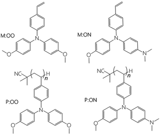 | ||
| Fig. 1 Chemical structure of the HTMs used in this study. Each monomer with its corresponding polymer. | ||
2 Results and discussion
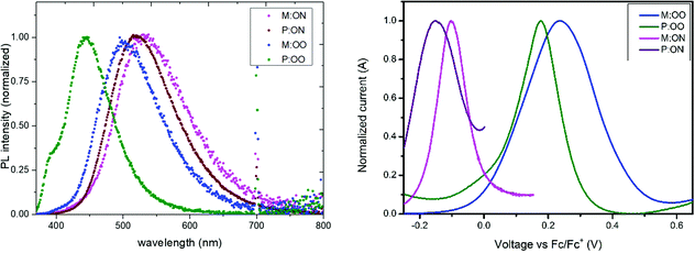
The synthetic route to both monomers and polymers is shown in Scheme 1 and detailed synthetic procedures can be found in the Experimental section. P:OO and P:ON were prepared by the free radical polymerization of M:OO and M:ON, respectively. Free radical polymerization was chosen to provide a cost-effective route to the polymeric HTMs, avoiding complications from controlled radical polymerization methods to directly compare monomers and polymers. The target triarylamines containing a styrene unit were synthesized by the palladium catalysed Buchwald–Hartwig24 coupling due to its scalability. All materials were characterised in detail by nuclear magnetic resonance (NMR) (1H and 13C) spectroscopy, elemental analysis and mass spectrometry (MS). We sought to determine polymer molecular weight by gel permeation chromatography, however we encountered column blockages. By MALDI TOF mass spectrometry (Fig. S2, ESI†) we could observe the lower molecular weight components and confirm the repeat units, however this technique is not able to determine average molecular weight.The optical properties of monomers and polymers were investigated by UV/Vis and photoluminescence (PL) spectroscopy in dichloromethane solution. All compounds exhibit a strong absorption around 300 nm almost independent of the substituents, with no significant absorption in the visible region. Transparent HTMs with no absorption in the visible region provide additional advantages and flexibility as they can be used in PSC cell architectures such as inverted and tandem structures where it is important that there is no competition with the perovskite layer. The monomers present two adjacent bands corresponding to π–π* and n–π* absorption, while for the polymers one single band from n–π* absorption is observed. Photoluminescence spectra of the materials as thin films are illustrated in Fig. 2, with solution data show in Fig. S3b (ESI†). In contrast to UV-Vis, the emission energies are significantly influenced by the substituents. The thin-film results show a clear redshift of the PL spectrum in the series with increasing electron-donating character of the substituents. This trend could be explained as an effective S1 energy stabilisation due to the presence of electron-donating groups of various strengths, likely linked with rotation around the N-aryl bond after excitation. Moreover, a hypsochromic shift is observed upon polymerization, which can be attributed to both the loss of the conjugated double bond and the steric shielding effect (solvent exclusion). The polymers have a more rigid and compact structure, which may lead to steric shielding of the interior units, such that lower interaction with the solvent molecules leads to less stabilisation of the emissive state explaining the observed blue-shifted emission. The optical band gaps, shown in Table 1, were determined from the intersection of the excitation and the emission spectra.
| HTM | λ max (nm) | ε (cm−1 M−1) | λ em (nm) | E gap (V) | E ox (V) | E HOMO (eV) | T g (°C) |
|---|---|---|---|---|---|---|---|
| a Excitation at λmax*. b Optical gap, determined from the intersection of the excitation and emission spectra. c From CV measurements and referenced to ferrocene. d E HOMO (eV) = −5.1 − Eox.25 | |||||||
| M:OO | 308*, 336 | 22![[thin space (1/6-em)]](https://www.rsc.org/images/entities/char_2009.gif) 500 500 |
457 | 3.15 | +0.22 | −5.32 | X |
| M:ON | 309*, 334 | 23![[thin space (1/6-em)]](https://www.rsc.org/images/entities/char_2009.gif) 500 500 |
424 | 3.29 | −0.10 | −5.00 | X |
| P:OO | 300* | 19![[thin space (1/6-em)]](https://www.rsc.org/images/entities/char_2009.gif) 000 000 |
395 | 3.39 | +0.19 | −5.29 | 252.8 |
| P:ON | 307* | 23![[thin space (1/6-em)]](https://www.rsc.org/images/entities/char_2009.gif) 000 000 |
511 | 2.99 | −0.15 | −4.95 | 252.8 |
| Spiro-OMeTAD | 385 | — | 424 | 3.05 | +0.03 | −5.13 | — |
The oxidation potential and derived energy levels of the HTMs are fundamental parameters for constructing high-performance PSCs. The electrochemical properties were investigated by cyclic voltammetry (CV) and square-wave voltammetry. From the CV measurements (Fig. S3a, ESI†), it can be noted that the redox peaks of all the HTMs are highly chemically and electrochemically reversible, indicating excellent chemical stability and rapid electron transfer. The HOMO energy levels of the compounds were estimated from the half-wave potential using ferrocene/ferrocenium as an internal standard in square-wave voltammetry experiments (Fig. 2, right). The four compounds show an oxidation process assigned to the oxidation of the side-chain redox-active group triarylamine moiety. The influence of the substituents is reflected by a shift in the potential of the redox couple. The oxidation of M:OO and P:OO occurs around +0.22 V and +0.19 V, whereas the electron donating Me2N-substituent of M:ON and P:ON causes a shift to lower potentials (−0.1 V and −0.15 V) thus increasing their HOMO energy level to −5.0 eV and −4.95 eV respectively. This makes M:ON and P:ON significantly stronger donor molecules than M:OO, P:OO and Spiro-OMeTAD. These observations were explained with density functional theory calculations using Gaussian 09 with B3LYP6-31(d) level of theory in dichloromethane (DCM). For the polymers, a model of the monomer fragment with saturated alkyl chain was used to calculate their electronic properties. The calculated trend of HOMO energy levels matches the experimental data, and they were shown to delocalise over the π orbitals of the triphenylamine unit and the peripheral substituents. The delocalisation of the HOMO onto the peripheral substituents (Fig. 3) explains the large shift in the oxidation potential upon changing the substituent from MeO- to Me2N-. A summary of the optical and electrochemical properties of these materials is presented in Table 1. These results indicate an energetically-favourable hole transfer from the perovskite (CH3NH3PbI3) to the HTM.
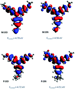 | ||
| Fig. 3 Molecular orbital distribution of HOMO of monomers and polymer model derivatives at B3LYP/6-31G(d) level of theory. | ||
Thermal properties of the monomers and polymers were estimated by Differential Scanning Calorimetry (DSC), and the results are displayed in the ESI† (Fig. S5 and S6). Both polymers (P:OO and P:ON) showed the same glass transition temperature of 252.8 °C. On the other hand monomers M:OO and M:ON, do not present Tg. M:OO presented a melting point of 74.7 °C and no melting point was found for M:ON. These results confirms that the polymers form a more stable amorphous glassy state with higher thermal stability.
To investigate the ability of the monomers and polymers to extract holes, we measured steady-state and transient photoluminescence (PL) decay. Samples were prepared by spin-coating of the perovskite onto a mesoporous Al2O3 layer with the HTM on top. Details of the sample preparation and measurement are described in the Experimental section. The perovskite exhibited a strong PL peak near 760 nm as shown in Fig. S7 (ESI†) and PL is largely quenched when any of the HTMs (M:OO, P:OO, M:ON and P:ON) was coated onto the perovskite, indicating an effective charge extraction into the HTM. From the transient PL decays (Fig. S8, ESI†), photoluminescence lifetimes were obtained by fitting the decays with exponentials. We calculated the efficiency of hole transfer, calculated as 1 − τq/(τ0 + τq), where τ0 and τq are the photoluminescence lifetimes of the perovskite in the absence and presence of the HTM layer, respectively (Table S1, ESI†). These were found to be 0.88 ± 0.03 (M:OO), 0.85 ± 0.05 (P:OO), 0.61 ± 0.01 (M:ON), 0.53 ± 0.02 (P:ON). It was found that monomers reduce the lifetime of the perovskite emission more effectively than polymers, indicating more effective charge extraction. Surprisingly, M:ON and P:ON showed lower hole-extraction yields than M:OO and P:OO, despite their lower oxidation potential, suggesting this is not the key factor in hole extraction efficiency.
We also sought to investigate charge mobility in the polymers by FET measurements by depositing the materials onto prepatterned chips with gold electrodes. We were unable however to observe significant gate effect, possibly due to mismatch of energy levels or electrode contacts. This may also indicate that mobility in the polymers is not ideal, which would affect the resulting solar cell performance, particularly Jsc, (vide infra) and remains an aspect for further optimisation in future studies.
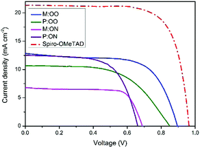
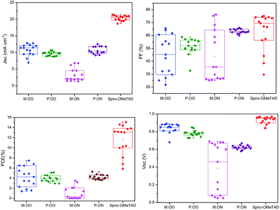
We prepared a set of perovskite solar cells in the configuration FTO/bl-TiO2/mp-TiO2/CH3NH3PbI3/HTM/Au (Fig. 4). All HTMs were doped using similar concentrations of additives [LiTFSi] and tBP (tert-butylpyridine) as described in the ESI.† The current density–voltage (J–V) characteristics were measured under simulated air mass 1.5 global (AM 1.5G) solar irradiation. Fig. 5 shows the J–V curves characteristic of the champion devices and the results are summarised in Table 2. All devices were fabricated in a single continuous study over 15 repeat cells for each HTM to facilitate comparison between the reported HTMs and Spiro-OMeTAD. Spiro-OMeTAD presented the highest efficiency of 15.09%. The corresponding values for M:OO, P:OO and P:ON of 7.48%, 5.28% and 5.14% are reasonable considering that this work represent the first solar cells study with these HTMs and that Spiro-OMeTAD has gone through extensive optimisation of doping and processing procedures for many years. For the polymer materials, the champion cells show significant hysteresis, although less so in the average Jsc (Fig. S9, ESI†). The most significant observation is that in comparison with both monomers and Spiro-OMeTAD, the polymers exhibit photovoltaic parameters with significantly smaller standard deviation, leading to average PCE 3.94% ± 0.68 for P:OO and 4.22% ± 0.48 whereas for Spiro-OMeTAD, M:OO and M:OO average values are 11.7% ± 2.96, 4.24% ± 2.03 and 1.03% ± 1.23. The difference in FF values are even greater with polymers showing 51.31% ± 6.41 for P:OO and 63.24% ± 1.71 and Spiro-OMeTAD, M:OO and M:ON presenting 62.92% ± 14.67, 44.67% ± 15.54 and 43.67% ± 19.98. These result can be attributed to the difference in the morphology. The polymers form a more stable amorphous state and have higher thermal stability which result in a more homogenous film deposition during the device fabrication. Accordingly, when comparing performance parameters with molecular design of the new materials, it is clearly more meaningful to make comparisons between the two polymers where the cells were very reproducible. Although PCE values in the polymers are very similar, we note the increase in the average short circuit current (Jsc) values upon increasing the electron donating character from 9.58 mA cm2 for P:OO to 10.68 mA cm−2 for P:ON. On the other hand, the HOMO level of P:ON is higher (Fig. 4, top) than P:OO leading to smaller open circuit voltage (Voc) value; 0.78 V for P:OO and 0.62 V for P:ON. Differences in fill factor are more difficult to interpret and may relate to film morphology as well as inherent electronic factors. Fig. 6 shows the box plots with the mean and standard deviation of the solar cell parameters and the results are summarised in Table S2 (ESI†).
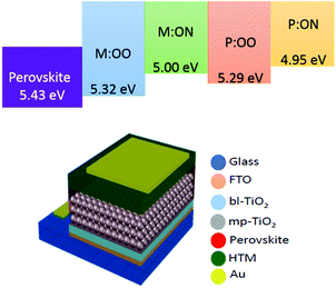 | ||
| Fig. 4 Top: Energy diagram for perovskite (CH3NH3PbI3), monomers and polymers. Bottom: Device structure in the configuration FTO/bl-TiO2/mp-TiO2/CH3NH3PbI3/HTM/Au. | ||
| HTM | PCE (%) | J sc (mA cm−2) | V oc (V) | FF (%) |
|---|---|---|---|---|
| M:OO | 7.48 | 12.81 | 0.89 | 65.54 |
| P:OO | 5.14 | 10.61 | 0.85 | 57.17 |
| M:ON | 3.52 | 6.79 | 0.68 | 76.19 |
| P:ON | 5.28 | 12.49 | 0.65 | 64.73 |
| Spiro-OMeTAD | 15.09 | 20.56 | 0.95 | 63.81 |
3 Conclusions
In conclusion, we present the synthesis and characterisation of two styrenic triphenylamine-based monomers and their corresponding side-chain polymers for use as HTMs in perovskite solar cells. The structures contained different electron-donating groups in the para-position, leading to significantly different redox potentials and HOMO energies. The optical, electrochemical, thermal properties and device performance of the monomers and polymers were compared in terms of their structure. From this study, it was found that despite offering lower efficiencies in comparison with Spiro-OMeTAD and monomers, the polymers presented much higher reproducibility in their solar cell performance parameters. The polymers have significantly smaller standard deviation in the power conversion efficiency and fill factor data which we attribute to better and more stable amorphous character resulting in a more homogeneous film. The results found in this work may encourage further efforts on polymeric HTMs with redox-active side groups for perovskite solar cells which may have advantages in manufacture and scale up due to enhanced reproducibility.4 Experimental details
4.1 Materials and synthesis
All reagents were purchased from either Sigma-Aldrich or Alfa-Aesar and they were used as received without further purification unless otherwise stated.4.2 Chemical characterization
1H and 13C NMR spectra were recorded on a Brucker Advance 500 spectrometer (500 MHz for 1H and 124 MHz for 13C) relative to deuterated solvents as indicated in individual synthesis description. MS were recorded on Bruker ESI Micro-Tof equipped with LC using electrospray ionization (ESI). Elemental analyses were carried out by Stephen Boyer at London Metropolitan University.4.3 Synthesis and characterisation
4-Ethenyl-N,N-bis(4-methoxyphenyl)benzenamine Pd2(dba)3 (1.31 mmol, 1.2 g), tri-o-tolylphosphine (6.5 mmol, 2 g), 4,4′-dimethoxydiphenylamine (43.62 mmol, 10 g) and NaOtBu (50 mmol, 4.8 g) were added into a Schlenk tube and dried under vacuum for 30 minutes. 4-Bromostyrene (5.8 mmol, 0.7 g) and toluene (30 mL) were all degassed and added to the reaction mixture and the contents heated at 110 °C overnight under N2. The crude material was purified first by an extraction with water following by a silica plug (70![[thin space (1/6-em)]](https://www.rsc.org/images/entities/char_2009.gif) :
:![[thin space (1/6-em)]](https://www.rsc.org/images/entities/char_2009.gif) 30 Hex/EtA) of the organic phase. Solvent was removed from the solution under vacuum and the product purified by flash column chromatography (SiO2, hexanes up to hexanes/EtOAc 80
30 Hex/EtA) of the organic phase. Solvent was removed from the solution under vacuum and the product purified by flash column chromatography (SiO2, hexanes up to hexanes/EtOAc 80![[thin space (1/6-em)]](https://www.rsc.org/images/entities/char_2009.gif) :
:![[thin space (1/6-em)]](https://www.rsc.org/images/entities/char_2009.gif) 20) to afford a yellow powder (5.3 g, 52.5% yield). 1H NMR (500 MHz, DMSO-d6) δ 7.31–7.24 (m, 2H), 7.05–6.98 (m, 4H), 6.96–6.88 (m, 4H), 6.76–6.69 (m, 2H), 6.61 (dd, J = 17.6, 11.0 Hz, 1H), 5.61 (dd, J = 17.6, 1.2 Hz, 1H), 5.08 (dd, J = 10.9, 1.3 Hz, 1H), 3.75 (s, 6H). 13C NMR (126 MHz, DMSO-d6) δ 119.65, 115.43, 111.73, 55.72, 39.77, 39.59. Anal. calcd for C22H21NO2: C, 79.73; H, 6.39; N, 4.23; found: (C, 79.81; H, 6.50; N, 4.34): [M]+ calcd 331.42 found 331.1571.
20) to afford a yellow powder (5.3 g, 52.5% yield). 1H NMR (500 MHz, DMSO-d6) δ 7.31–7.24 (m, 2H), 7.05–6.98 (m, 4H), 6.96–6.88 (m, 4H), 6.76–6.69 (m, 2H), 6.61 (dd, J = 17.6, 11.0 Hz, 1H), 5.61 (dd, J = 17.6, 1.2 Hz, 1H), 5.08 (dd, J = 10.9, 1.3 Hz, 1H), 3.75 (s, 6H). 13C NMR (126 MHz, DMSO-d6) δ 119.65, 115.43, 111.73, 55.72, 39.77, 39.59. Anal. calcd for C22H21NO2: C, 79.73; H, 6.39; N, 4.23; found: (C, 79.81; H, 6.50; N, 4.34): [M]+ calcd 331.42 found 331.1571.
4-Methoxy-4′-(dimethylamino)diphenylamine 4-bromo-N,N-dimethylaniline (5 g, 25 mmol), p-anisidine (3.7 g, 30 mmol), Pd2(dba)3 (115 mg, 0.125 mmol), JohnPhos ligand (74 mg, 0.250 mmol) and NaOtBu (3.35 g, 35 mmol) were minutes. Previously degassed dry toluene (66 mL) was added and the mixture was stirred at 80 °C for 48 h under N2. The crude material was purified first by an extraction with water/DCM and a silica plug (70![[thin space (1/6-em)]](https://www.rsc.org/images/entities/char_2009.gif) :
:![[thin space (1/6-em)]](https://www.rsc.org/images/entities/char_2009.gif) 30 Hex/EtOAc). Solvent was removed from the solution under vacuum and the product was purified by flash column chromatography (SiO2, hexane/EtOAc 9.9
30 Hex/EtOAc). Solvent was removed from the solution under vacuum and the product was purified by flash column chromatography (SiO2, hexane/EtOAc 9.9![[thin space (1/6-em)]](https://www.rsc.org/images/entities/char_2009.gif) :
:![[thin space (1/6-em)]](https://www.rsc.org/images/entities/char_2009.gif) 0.10) to afford a yellow powder (5.3 g, 52.5% yield). 1H NMR (500 MHz, benzene-d6) δ 6.97–6.90 (m, 2H), 6.83–6.74 (m, 4H), 6.65–6.60 (m, 2H), 4.73 (s, 1H), 3.37 (s, 3H), 2.56 (s, 6H).
0.10) to afford a yellow powder (5.3 g, 52.5% yield). 1H NMR (500 MHz, benzene-d6) δ 6.97–6.90 (m, 2H), 6.83–6.74 (m, 4H), 6.65–6.60 (m, 2H), 4.73 (s, 1H), 3.37 (s, 3H), 2.56 (s, 6H).
4-Ethenyl-N,N-bis(4-methoxy-4′(dimethylamino)diphenylamine Pd2(dba)3 (0.25 mmol, 0.23 g), tri-o-tolylphosphine (1.24 mmol, 0.38 g), 4-methoxy-4′-(dimethylamino)diphenylamine (8.26 mmol, 2 g) and NaOtBu (9.5 mmol, 0.9) were added into a Schlenk tube and dried under vacuum for 30 minutes. 4-Bromostyrene (5.8 mmol, 0.7 g) and toluene (15 mL) were all degassed and added to the reaction mixture and the contents heated at 110 °C overnight under N2. The crude material was purified by an extraction with water following by a silica plug (70![[thin space (1/6-em)]](https://www.rsc.org/images/entities/char_2009.gif) :
:![[thin space (1/6-em)]](https://www.rsc.org/images/entities/char_2009.gif) 30 Hex/EtA). Solvent was removed from the solution under vacuum and the product purified by flash column chromatography (SiO2, hexanes up to hexanes/EtOAc 80
30 Hex/EtA). Solvent was removed from the solution under vacuum and the product purified by flash column chromatography (SiO2, hexanes up to hexanes/EtOAc 80![[thin space (1/6-em)]](https://www.rsc.org/images/entities/char_2009.gif) :
:![[thin space (1/6-em)]](https://www.rsc.org/images/entities/char_2009.gif) 20) to afford a thick yellow oil (1.6 g, 80% yield). 1H NMR (500 MHz, DMSO-d6) δ 7.28–7.21 (m, 2H), 7.05–6.97 (m, 2H), 7.00–6.91 (m, 2H), 6.94–6.86 (m, 2H), 6.77–6.66 (m, 4H), 6.60 (dd, J = 17.6, 11.0 Hz, 1H), 5.58 (dd, J = 17.6, 1.2 Hz, 1H), 5.05 (dd, J = 10.9, 1.2 Hz, 1H), 3.74 (s, 3H), 2.88 (s, 6H). 13C NMR (126 MHz, DMSO-d6) δ 148.93, 148.11, 140.62, 136.72, 136.47, 128.92, 127.48, 127.35, 126.79, 118.83, 115.30, 114.02, 111.27, 55.71, 40.82, 39.77. Anal. calcd for C23H24N2O: C, 80.20; H, 7.02; N, 8.13; found: C, 80.05; H, 7.16; N, 8.05): [M]+ calcd 344.46 found 345.1961.
20) to afford a thick yellow oil (1.6 g, 80% yield). 1H NMR (500 MHz, DMSO-d6) δ 7.28–7.21 (m, 2H), 7.05–6.97 (m, 2H), 7.00–6.91 (m, 2H), 6.94–6.86 (m, 2H), 6.77–6.66 (m, 4H), 6.60 (dd, J = 17.6, 11.0 Hz, 1H), 5.58 (dd, J = 17.6, 1.2 Hz, 1H), 5.05 (dd, J = 10.9, 1.2 Hz, 1H), 3.74 (s, 3H), 2.88 (s, 6H). 13C NMR (126 MHz, DMSO-d6) δ 148.93, 148.11, 140.62, 136.72, 136.47, 128.92, 127.48, 127.35, 126.79, 118.83, 115.30, 114.02, 111.27, 55.71, 40.82, 39.77. Anal. calcd for C23H24N2O: C, 80.20; H, 7.02; N, 8.13; found: C, 80.05; H, 7.16; N, 8.05): [M]+ calcd 344.46 found 345.1961.
P:OO was synthesised via free radical polymerisation (FRP). An ampoule was charged with M-OO (1.0 g, 3.0 mmol), AIBN (5.0 mg, 30 μmol) and anhydrous toluene (2 mL). The resulting solution was heated at 120 °C for 20 hours. After this time, the reaction mixture was cooled to ambient temperature. The reaction mixture was added dropwise to methanol (75 mL), inducing the precipitation of the polymer, which was collected by filtration. It was necessary to re-dissolve (in a minimum of THF) and re-precipitate (in methanol) the collected polymer to ensure that all remaining monomer was removed. Finally, the purified polymer was dried in vacuum, yielding an off-white solid. Yield: 0.55 g. 1H NMR (500 MHz, DMSO-d6) δ 1.4–1.6 (chain, 3H), 3.5–3.8 (OMe, 6H), 6.3–7.0 (aromatic, 12H).
P:ON was synthesised by an analogous route, yielding an off-white solid. 1H NMR (500 MHz, DMSO-d6) δ 1.5–1.7 (chain, 3H), 2.7–3.2 (NMe2, 6H), 3.5–3.8 (OMe, 3H), 6.5–7.3 (aromatic, 12H).
4.4 Thermal characterisation
Differential scanning calorimetry (DSC) was performed on NETZSCH STA 449F1 at a scan rate of 5 K min−1 under nitrogen atmosphere in DSC/TG aluminium pan. The measurement range was 25 °C to 300 °C.4.5 Optical characterization
Solution UV-visible absorption spectra were recorded using a Jasco V-670 UV/Vis/NIR spectrometer controlled with SpectraManager software. Photoluminescence (PL) spectra were recorded with a Fluoromax-3 fluorimeter controlled by ISAMA software. All samples were measured in a 1 cm cell at room temperature with dichloromethane as solvent. Concentrations of 5 × 10⁻⁵ M and 2 × 10⁻⁶ M were used for UV/Vis and PL respectively.4.6 Electrochemical characterization
All cyclic voltammetry measurements were carried out in freshly distilled CH2Cl2 using 0.3 M [TBA][BF4] electrolyte in a three electrode system, with each solution being purged with N2 prior to measurement. The working electrode was a Pt disk. The reference electrode was Ag/AgCl and the counter electrode was a Pt rod. All measurements were made at room temperature using a μAUTOLAB Type III potentiostat driven by the electrochemical software GPES; square wave voltammetry (SWV) was carried out at a step potential of 2 mV, square wave amplitude of 25 mV, and a square wave frequency of 25 Hz. Ferrocene was used as the internal standard in each measurement.4.7 Computational details
All calculations were carried out using the Gaussian 09 program with Lee Yang–Parr correlation functional (B3LYP) level of theory. All atoms were described by the 6-31G(d) basis set. All structures were input and processed through the Avogadro software package.4.8 Perovskite solar cells and characterisation
FTO substrates (7 Ω sq−1) were etched with zinc powder and HCl (2 M aqueous solution) to give the desired electrode patterning. The substrates were cleaned in a solution of detergent and deionised water before sequential sonication in deionised water, acetone and isopropanol and a 10 minute oxygen plasma treatment to remove the last traces of organics. The FTO substrates were subsequently coated with a compact layer of TiO2 (50 nm) by spray pyrolysis deposition using titanium diisopropoxide bis(acetylacetonate) in anhydrous ethanol as precursor solution (volume ratio 1![[thin space (1/6-em)]](https://www.rsc.org/images/entities/char_2009.gif) :
:![[thin space (1/6-em)]](https://www.rsc.org/images/entities/char_2009.gif) 9). After cooling from 450 °C, a dilute suspension of TiO2 nanoparticles (2
9). After cooling from 450 °C, a dilute suspension of TiO2 nanoparticles (2![[thin space (1/6-em)]](https://www.rsc.org/images/entities/char_2009.gif) :
:![[thin space (1/6-em)]](https://www.rsc.org/images/entities/char_2009.gif) 7 wt, Dyesol 30NR-D: ethanol) was deposited by spin coating (4500 rpm, 30 seconds). The samples were then heated at 150 °C for 10 minutes, followed by sintering at 550 °C for 30 minutes. Upon cooling, samples were immediately transferred to a N2-filled glovebox (H2O and O2 levels <0.5 ppm). The perovskite (CH3NH3PbI3) layer was deposited by spin-coating a solution containing 576 mg of PbI2 and 199 mg of MAI in a mixture of 0.8 mL DMF and 0.2 mL of DMSO (4000 rpm, 30 seconds), with 100 μL of ethyl acetate deposited 10 seconds before the end of the spin cycle. The substrates were then annealed at 100 °C for 10 minutes in the glovebox. The hole transporters materials were dissolved in chlorobenzene (75 mg mL−1) with the standard additives 5-tert-butylpyridine (32 μL) and lithium bis(trifluoromethanesulfonyl) imide (20 μL, 520 mg mL−1 solution in acetonitrile). Hole transport solutions were spin-coated at 4000 rpm for 30 seconds, after which a 80 nm thick gold electrode was evaporated at 10−4 Torr. For measuring the performance of the solar cells, simulated sunlight was generated using an AAA-rated solar simulator (Newport) calibrated with KG-5 filtered Si reference cell (Newport).
7 wt, Dyesol 30NR-D: ethanol) was deposited by spin coating (4500 rpm, 30 seconds). The samples were then heated at 150 °C for 10 minutes, followed by sintering at 550 °C for 30 minutes. Upon cooling, samples were immediately transferred to a N2-filled glovebox (H2O and O2 levels <0.5 ppm). The perovskite (CH3NH3PbI3) layer was deposited by spin-coating a solution containing 576 mg of PbI2 and 199 mg of MAI in a mixture of 0.8 mL DMF and 0.2 mL of DMSO (4000 rpm, 30 seconds), with 100 μL of ethyl acetate deposited 10 seconds before the end of the spin cycle. The substrates were then annealed at 100 °C for 10 minutes in the glovebox. The hole transporters materials were dissolved in chlorobenzene (75 mg mL−1) with the standard additives 5-tert-butylpyridine (32 μL) and lithium bis(trifluoromethanesulfonyl) imide (20 μL, 520 mg mL−1 solution in acetonitrile). Hole transport solutions were spin-coated at 4000 rpm for 30 seconds, after which a 80 nm thick gold electrode was evaporated at 10−4 Torr. For measuring the performance of the solar cells, simulated sunlight was generated using an AAA-rated solar simulator (Newport) calibrated with KG-5 filtered Si reference cell (Newport).
4.9 Time resolved photoluminescence
A 35% dilution of an AI-7 Al2O3 paste in H2O was made up and stirred overnight. Squares of VWR super premium microscope slides were rinsed in IPA in a sonicator for five minutes prior to spin coating. The solution of alumina was pipetted onto the microscope slides while on the vacuumed O-ring. The paste was spun at 4500 rpm, with an acceleration of 12![[thin space (1/6-em)]](https://www.rsc.org/images/entities/char_2009.gif) 000 rpm s−2 for 30 s. The films were then placed in a 150 °C oven for 1 hour and left to cool for 20 min. For the deposition of the perovskite layer 1 M solution of PbI2 and MeNH3I in DMSO was prepared. This solution was spin-coated onto the glass slides covered with the mesoporous oxide via 3-step spin coating process: (i) 1000 rpm, 10 s, 2000 acc; (ii) 5000 rpm, 20 s, 2000 acc; (iii) 6000 rpm, 20 s, 2000 acc. Toluene (300 μL) was dropped on the substrates by the end of the second step. The films were then annealed at 50 °C for 20 min and at 100 °C for 25–30 min and cooled down to room temperature. A 20 mg mL−1 solution in chlorobenzene of the corresponding HTM was spin-coated onto the perovskite layer at 200 rpm for 30 s, with an acceleration of 2000. UV-Vis was performed on a PerkinElmer UV/VIS Spectrometer Lambda 25. Photoluminescence spectra were recorded on a Horiba Yobin-Ybon Fluorolog-3 spectrofluorometer, using an excitation wavelength of 450 nm and slit widths of 10 nm. Time-correlated single-photon counting was recorded using a Deltaflex spectrometer (Horiba Yobin-Tbon), using an excitation of 404 nm and measuring the emission of the perovskite at 770 nm.
000 rpm s−2 for 30 s. The films were then placed in a 150 °C oven for 1 hour and left to cool for 20 min. For the deposition of the perovskite layer 1 M solution of PbI2 and MeNH3I in DMSO was prepared. This solution was spin-coated onto the glass slides covered with the mesoporous oxide via 3-step spin coating process: (i) 1000 rpm, 10 s, 2000 acc; (ii) 5000 rpm, 20 s, 2000 acc; (iii) 6000 rpm, 20 s, 2000 acc. Toluene (300 μL) was dropped on the substrates by the end of the second step. The films were then annealed at 50 °C for 20 min and at 100 °C for 25–30 min and cooled down to room temperature. A 20 mg mL−1 solution in chlorobenzene of the corresponding HTM was spin-coated onto the perovskite layer at 200 rpm for 30 s, with an acceleration of 2000. UV-Vis was performed on a PerkinElmer UV/VIS Spectrometer Lambda 25. Photoluminescence spectra were recorded on a Horiba Yobin-Ybon Fluorolog-3 spectrofluorometer, using an excitation wavelength of 450 nm and slit widths of 10 nm. Time-correlated single-photon counting was recorded using a Deltaflex spectrometer (Horiba Yobin-Tbon), using an excitation of 404 nm and measuring the emission of the perovskite at 770 nm.
Conflicts of interest
There are no conflicts of interest to declare.Acknowledgements
RFP thanks CONACYT, Mexico for a PhD studentship. We thank EPSRC EP/H040218/1; EP/M023532/1 for financial support.Notes and references
- A. Kojima, K. Teshima, Y. Shirai and T. Miyasaka, J. Am. Chem. Soc., 2009, 131, 6050–6051 CrossRef CAS PubMed.
- Y. Zhou and K. Zhu, ACS Energy Lett., 2016, 1, 64–67 CrossRef CAS.
- NREL, efficiency-chart.png (4348 × 2415), https://www.nrel.gov/pv/assets/images/efficiency-chart.png, (accessed 21 July 2017).
- P. Gao, M. Grätzel, M. K. Nazeeruddin, K. Zheng, A. Yartsev, T. Pascher, T. Harlang, P. Chabera, T. Pullerits, A. Stepanov, J. P. Wolf, V. Sundstrom, R. Mosca, D. G. Schlom, J. W. Ager and R. Ramesh, Energy Environ. Sci., 2014, 7, 2448–2463 RSC.
- S. D. Stranks and H. J. Snaith, Nat. Nanotechnol., 2015, 10, 391–402 CrossRef CAS PubMed.
- P. Docampo, S. Guldin, T. Leijtens, N. K. Noel, U. Steiner and H. J. Snaith, Adv. Mater., 2014, 26(24), 4013–4030 CrossRef CAS PubMed.
- V. E. Madhavan, I. Zimmermann, C. Roldán-Carmona, G. Grancini, M. Buffiere, A. Belaidi and M. K. Nazeeruddin, ACS Energy Lett., 2016, 1, 1112–1117 CrossRef CAS.
- S. Ito, in Inorganic Hole-Transporting Materials for Perovskite SolarCell, Organic-Inorganic Halide Perovskite Photovoltaics, ed. N.-G. Park, M. Graetzel and T. Miyasaka, Springer, 2017, DOI:10.1007/978-3-319-35114-8_14.
- S. Lv, Y. Song, J. Xiao, L. Zhu, J. Shi, H. Wei, Y. Xu, J. Dong, X. Xu, S. Wang, Y. Xiao, Y. Luo, D. Li, X. Li and Q. Meng, Electrochim. Acta, 2015, 182, 733–741 CrossRef CAS.
- M. Daskeviciene, S. Paek, Z. Wang, T. Malinauskas, G. Jokubauskaite, K. Rakstys, K. T. Cho, A. Magomedov, V. Jankauskas, S. Ahmad, H. J. Snaith, V. Getautis and M. K. Nazeeruddin, Nano Energy, 2017, 32, 551–557 CrossRef CAS.
- P. Ganesan, K. Fu, P. Gao, I. Raabe, K. Schenk, R. Scopelliti, J. Luo, L. H. Wong, M. Grätzel and M. K. Nazeeruddin, Energy Environ. Sci., 2015, 8, 1986–1991 RSC.
- L. Calió, S. Kazim, M. Grätzel and S. Ahmad, Angew. Chem., Int. Ed., 2016, 55, 14522–14545 CrossRef PubMed.
- M. Grätzel, U. Bach, D. Lupo, P. Comte, J. E. Moser, F. Weissörtel, J. Salbeck and H. Spreitzer, Nature, 1998, 395, 583–585 CrossRef.
- S. Ameen, M. A. Rub, S. A. Kosa, K. A. Alamry, M. S. Akhtar, H.-S. Shin, H.-K. Seo, A. M. Asiri and M. K. Nazeeruddin, ChemSusChem, 2016, 9, 10–27 CrossRef CAS PubMed.
- M. Thelakkat, Macromol. Mater. Eng., 2002, 287, 442 CrossRef CAS.
- D. Bi, L. Yang, G. Boschloo, A. Hagfeldt and E. M. J. Johansson, J. Phys. Chem. Lett., 2013, 4, 1532–1536 CrossRef CAS PubMed.
- Z. Yu, Y. Zhang, X. Jiang, X. Li, J. Lai, M. Hu, M. Elawad, G. G. Gurzadyan, X. Yang, L. Sun, S. Wang, Y. Luo, Q. Meng, X. Li and A. Hagfeldt, RSC Adv., 2017, 7, 27189–27197 RSC.
- M. Wong-Stringer, J. E. Bishop, J. A. Smith, D. K. Mohamad, A. J. Parnell, V. Kumar, C. Rodenburg, D. G. Lidzey, P. L. Burn, I. R. Gentle, P. Meredith, S. Il Seok, M. K. Nazeeruddin, M. Gratzel and A. Hagfeldt, J. Mater. Chem. A, 2017, 30, 1410 Search PubMed.
- B. Yang, M. Mahjouri-Samani, C. M. Rouleau, D. B. Geohegan and K. Xiao, Phys. Chem. Chem. Phys., 2016, 18, 27067–27072 RSC.
- Jhun Mo Son, Y. Sakaki, K. Ogino and H. Sato, IEEE Trans. Electron Devices, 1997, 44, 1307–1314 CrossRef CAS.
- S. Hüttner, M. Sommer, U. Steiner and M. Thelakkat, Appl. Phys. Lett., 2010, 96, 073503 CrossRef.
- E. M. Barea, G. Garcia-Belmonte, M. Sommer, S. Hüttner, H. J. Bolink and M. Thelakkat, Thin Solid Films, 2010, 518, 3351–3354 CrossRef CAS.
- R. Schroot, U. S. Schubert and M. Jäger, Macromolecules, 2015, 48, 1963–1971 CrossRef CAS.
- T. R. M. Rauws and B. U. W. Maes, Chem. Soc. Rev., 2012, 41, 2463–2497 RSC.
- C. M. Cardona, W. Li, A. E. Kaifer, D. Stockdale and G. C. Bazan, Adv. Mater., 2011, 23, 2367–2371 CrossRef CAS PubMed.
Footnote |
| † Electronic supplementary information (ESI) available. See DOI: 10.1039/c8cp04162h |
| This journal is © the Owner Societies 2018 |


