
 Open Access Article
 This Open Access Article is licensed under a Creative Commons Attribution-Non Commercial 3.0 Unported Licence
Influence of quasi-particle density over polaron mobility in armchair graphene nanoribbons
Gesiel Gomes
Silva
ab,
Wiliam Ferreira
da Cunha
b,
Rafael Timóteo
de Sousa Junior
 c,
Antonio Luciano
Almeida Fonseca
d,
Luiz Antônio
Ribeiro Júnior
*de and
Geraldo Magela
e Silva
b
c,
Antonio Luciano
Almeida Fonseca
d,
Luiz Antônio
Ribeiro Júnior
*de and
Geraldo Magela
e Silva
b
aGoiás Federal Institute of Education, Science and Technology, Luziânia, Goiás 72.811-580, Brazil
bInstitute of Physics, University of Brasília, Brasília, 70910-900, Brasília, Brazil
cDepartment of Electrical Engineering, University of Brasília, CP04455, Brasília, 70919-970, Brazil
dInternational Center for Condensed Matter Physics, University of Brasília, P.O. Box 04513, 70910-900, Brasília, Brazil
eDepartment of Physics, Chemistry and Biology (IFM), Linköping University, SE-581 83 Linköping, Sweden. E-mail: luiju@ifm.liu.se
First published on 22nd May 2018
Abstract
An important aspect concerning the performance of armchair graphene nanoribbons (AGNRs) as materials for conceiving electronic devices is related to the mobility of charge carriers in these systems. When several polarons are considered in the system, a quasi-particle wave function can be affected by that of its neighbor provided the two are close enough. As the overlap may affect the transport of the carrier, the question concerning how the density of polarons affect its mobility arises. In this work, we investigate such dependence for semiconducting AGNRs in the scope of nonadiabatic molecular dynamics. Our results unambiguously show an impact of the density on both the stability and average velocity of the quasi-particles. We have found a phase transition between regimes where increasing density stops inhibiting and starts promoting mobility; densities higher than 7 polarons per 45 Å present increasing mean velocity with increasing density. We have also established three different regions relating electric field and average velocity. For the lowest electric field regime, surpassing the aforementioned threshold results in overcoming the 0.3 Å fs−1 limit, thus representing a transition between subsonic and supersonic regimes. For the highest of the electric fields, density effects alone are responsible for a stunning difference of 1.5 Å fs−1 in the mean carrier velocity.
Introduction
In recent years, graphene has attracted great interest from the scientific community due to its electronic properties such as high electric conductivity, as well as to the possibility of implementing alternative technology for electronic devices.1–6 It is well known that a whole pristine graphene sheet has no bandgap,7 which is an undesirable trait for the development of electronics devices based on semiconductor technology. As derived structures, armchair graphene nanoribbons (AGNRs) are strips extracted from graphene sheets. Interestingly, AGNRs may have a finite bandgap varying according to the width of the nanoribbons.8 Such nanoribbons are usually classified into different families depending on their width. Considering the number of sites that compose the ribbon width, AGNRs can be of 3p, 3p + 1 and 3p + 2 nature, for a given integer p. As only AGNRs of the 3p and 3p + 1 families show semiconducting gaps, these are the most important class of nanoribbons as far as electronics is concerned.9Generally, simulations aiming to investigate charge dynamics in AGNRs consider the presence of a single quasi-particle. This kind of assumption is undoubtedly a simplification but a useful one, for it allows one to gain a deep phenomenological understanding of the charge behavior through the chain,9 how it may interact with defects,10 and the generation mechanism of charge carriers,11 among many other insights. If, on the other hand, one is concerned with the actual development of new nanodevices, the first step is to assess the behavior of the system when more than one charge carrier is present. This is because actual devices typically use high charge carrier densities. Logically, the quasi-particles will interact with each other and both charge localization and lattice deformation ought to be altered. Even more critical, as a result, when a considerable density of charge carriers is present, the dynamics of the system as a whole might be severely affected. Thus, considering higher densities is a decisive step towards developing a more realistic model. In this sense it is a requisite condition for the development of AGNR technology to investigate how charge carrier density can impact charge dynamics in these structures.
A similar reasoning has encouraged Ribeiro12 and coworkers to investigate how the concentration of charge carriers is relevant to the dynamics of oppositely charged polaron recombination in conjugated polymers. They showed the dependence of their results on the initial concentration of charge carriers and the electric field strength. The group has also13 investigated the relation between the appearance and stability of polarons with different values of the electron–phonon coupling constant in AGNRs. They showed that the characteristic value of the coupling constant for the appearance of the polaron depends on the width of the AGNR. It was also verified that the velocity of polarons in an AGNR decreases when the coupling constant increases. This result is especially accentuated when the electric field strength is high. In another theoretical contribution14 it was verified that an increase in the electron–phonon coupling constant favors the localization of the polaron charge in an AGNR. The studies of the charge dynamics for families 3p and 3p + 1 of AGNRs showed that the polaron mobility reduces when the coupling constant increases. Naturally these results are linked: a greater polaron charge localization leads to a decreased polaron mobility. Another result demonstrated was about the polaron saturation velocity. For a given value of the coupling constant, the polaron saturation velocity increases with the nanoribbon width. Johansson and Stafström15 studied the relationship between polaron velocity in a one-dimensional conjugated polymer chain and the electric field intensity. It was found that for an electric field intensity less than 0.135 mV Å−1, the polaron velocity is slightly below the velocity of sound in this polymer chain. Furthermore, there is an apparent discontinuity in the velocity of the polaron, whereby for fields slightly larger than this limit, the velocity of the polaron would go to a supersonic regime. We conclude that a similar investigation considering the effects of charge carrier density and electric field on the transport properties of AGNRs is highly required.
In this work our goal is to study how quasi-particle density impacts the velocity of these very carriers in AGNRs of the 3p + 1 family. The simulations were performed with different intensities of electric field, in order to investigate the influence of electric field intensity when more than one quasi-particle is considered on the charge dynamics on the AGNRs. In addition, we describe a phase transition for the velocities of the quasi-particles from subsonic to supersonic regimes. In AGNRs, as in conjugated polymers, several kinds of quasi-particle may arise as a result of the coupling between the electronic and the lattice degrees of freedom. Among these quasi-particles, the most usual one that serves as charge carrier is the polaron.16 A polaron is constructed in our system by removing an electron from the highest occupied molecular orbital (HOMO) and then self consistently solving the model equations. In the present work, we make use of a modified hybrid tight-binding 2D model that includes lattice relaxation in a first order expansion. Thus, we simultaneously treat coupled electrons and phonons. The system is evolved by employing a molecular dynamics approach in the scope of the Ehnrenfest methodology. The electrons are treated using the Schrödinger equation and for the lattice we used Euler–Lagrange equations.
Methodology
We make use of a hybrid two-dimensional model Hamiltonian in which the lattice is classically treated and π-electrons are treated in the second quantization formalism. An electron–phonon coupling constant is included in an otherwise tight-binding Hamiltonian, thus connecting electrons and phonons by introducing relaxation effects to the lattice. As a result of this coupling, quasi-particles are allowed to occur. Because the lattice displacements are considerably small, amounting to oscillating displacements of not much more than 2%, σ-bonds are treated in an harmonic approximation. This very argument can also be used to justify considering the hopping integral associated with π-electrons in a first order expansion according to:| tij = t0 − αyij. | (1) |
In eqn (1)t0 is the hopping integral traditionally employed by pure tight-binding models. yij stands for the variation of the bond length between two arbitrary neighboring i and j sites. α is the aforementioned electron–phonon coupling constant, responsible for the connection between the degrees of freedom of the electrons and lattice. The values used for these constants are 2.7 eV and 4.1 eV Å−1, respectively, the choice of which was consistent with that accepted in the literature.17,18
In this work, the electric field plays an important role in driving the polarons throughout the lattice. This excitation is introduced into the system by modifying eqn (1), i.e., performing a Peielrs substitution on the phase factor to included a time-dependent vector potential19 as follows:
| tij = e−iγA(t)(t0 − αyij). | (2) |
Here, γ ≡ ea/ħc, a is the lattice parameter, e is the absolute value of electronic charge and c is the velocity of light. The time-dependent electric field is related to the vector potential by  . It should be noted that we decided to turn the field on adiabatically because an abrupt implementation would lead to the artificial inclusion of numerical errors, thus causing further non-physical destabilization of the lattice.
The Hamiltonian of the system can be expressed by
 | (3) |
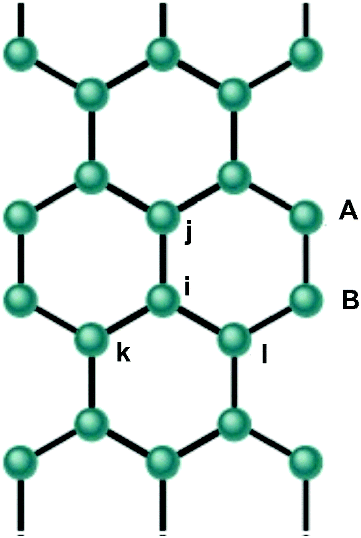 | ||
| Fig. 1 Schematic representation of an arbitrary AGNR. The site indexed as “i” has three neighbors, namely, “j”, “l” and “k”. | ||
C † i,s is the creation operator of a π-electron with spin s in the i-th site and Cj,s is the annihilation operator of a π-electron with spin s in the j-th site. K is the elastic harmonic constant, whose value was set to 21 eV Å−2.17,20 The kinetic energy of the sites is written in terms of momenta of the sites Pi, where M is the mass of each site. All the interactions considered in the systems are described by means of this model Hamiltonian. Therefore, on solving the equations of motion we do not need to carry out any other further modification of the system.
From an initial set of coordinates, yij, and the first term of eqn (3), an initial electronic Hamiltonian can be constructed. The initial self-consistent state is obtained through the diagonalization of this electronic Hamiltonian coupled with the equation of motion of the lattice given by  , in an initial static configuration. This solution consists of obtaining the eigenvalues (energies Ek) and eigenvectors (wave functions ψj,k) and the corresponding bond variations yij at the initial time.
The iterative solution of the stationary case consists of repeating this process self-consistently until a given convergence criterion is met. At the end of this process an initial self-consistent state related to the degrees of freedom of both the electrons and the lattice is obtained.
By considering eqn (3), one can construct the Lagrangian of the system. It follows that the solution of the lattice can be classically obtained through the associated Euler–Lagrange equation:
 | (4) |
 | (5) |
 | (6) |
In the last equation the sum is carried out over the occupied states only. Eqn (6) represents the terms that link the classical and quantum parts of the solution.
The time evolution of the system from the self consistent initial state is obtained through the solutions of the time-dependent Schrödinger equation for electrons and the Euler–Lagrange equations (eqn (4)) for the lattice. The wave function can be expanded in terms of a basis set of eigenstates of the electronic Hamiltonian at each instant t (|ϕ(t)〉). Consequently, the time evolution of the wave function in the instant t + dt takes the form
 | (7) |
The time evolution of the lattice dynamics is achieved from the solution of the Euler–Lagrange equation with a new Lagrangian constructed from the new wave functions (eqn (7)). This solution leads to a Newton-type equation21 which describes the lattice behavior
 | (8) |
Results
As we aim to study how the density of quasi-particles affects the charge transport in AGNRs, we first need to choose a specific representative system. First of all, because narrow 3p + 1 AGNRs consist of systems that present a characteristic semiconducting bandgap, we decided to carry out our simulations with a 4 sites wide AGNR. The narrower the nanoribbon, the bigger the confinement of the wave functions along its width. This points towards more stable localized states such as polarons, which are an important asset as far as applications in organic electronics are concerned. As our focus is the inclusion of several polarons in the chain, the stability aspect becomes crucial. This, together with the advantages narrow systems present as semiconducting systems, encouraged us to choose the narrowest 3p + 1 AGNR representative.As for the length of the nanoribbon, it should be noted that the structure must be long enough so that no edge effects are present and that the polarons' wave functions do not completely overlap among one another, eventually giving rise to different kinds of excitations by means of recombination. On the other hand, these systems should not be so large as to make the calculations prohibitively expensive computationally. To obtain a good compromise between reliability of the desired physical scenario and computational feasibility we start by investigating what would be the minimum length of the nanoribbon to clearly observe the presence of a polaron in our system. In order to do this, we gradually increased the length of the nanoribbon starting from 4 × 30 and growing until 4 × 90, as shown in Fig. 2. In each case we simulated the presence of a single polaron by extracting an electron and finding the initial self-consistent solution as explained in the previous section. From Fig. 2(a) one can see that for nanoribbons smaller that 50 sites long the charge is completely delocalized, being distributed over the whole nanoribbon. This means that, in these cases, a polaron could not be formed, for no localization characteristic of a quasi-particle takes place. For nanoribbon 4 × 60, corresponding to approximately 90 Å in length, however, one can see that the charge density is already localized in a region smaller that the size of the nanoribbon. This unambiguously characterizes the localization corresponding to a quasiparticle; in this case, a polaron.
 | ||
| Fig. 2 Schematic representation of a 4 × M AGNR where M = 30, 40, 50, 60, 70, 80 and 90. (a) One polaron in AGNR. (b) Two polarons in AGNR. | ||
Considering the nature of the present contribution, obtaining a minimum value for accommodating a single polaron is not enough. Because we are concerned with density effects, we should find the smallest chain that can support higher densities of polarons without degenerating these quasi-particles with considerable overlap. Fig. 2(b) corresponds to the same systems shown on the previous figure but now with two polarons, obtained from the self-consistent solution with the extraction of two electrons, thus consisting of twice the density. One can see that, although the center of charges can be distinguished even for the shortest of the nanoribbons, it is only for lengths larger that 60 sites that one can clearly observe two distinct entities, as opposed to an eventual two centered single quasi-particle. This is because for AGNRs of lengths 30, 40 and 50, the size of each polaron is objectively larger than half the size of the nanoribbon. The 4 × 60 nanoribbon is the intermediate case; the size of the polarons it bears is probably roughly half its size. It is only for the 4 × 70 AGNR case, with approximately 100 Å of length, that we can be confident to characterize two distinct polarons. This can be confirmed by the absence of charge density between the two positive charge accumulations.
Importantly, when comparing the minimal length to observe one polaron to that of observing two, we can conclude that the nanoribbon length and the number of quasi-particles do not keep in direct proportion. Otherwise, it would be necessary to have a nanoribbon of approximately 180 Å to distinguish two polarons; that is to say, a system 80% greater in relation to that obtained in Fig. 2(b). This result is interesting for the purposes of this work because it allows us to simulate various quasi-particles in an AGNR, without having to consider too large a system which would lead to a great computational cost.
Taking into account ten as the highest desired number of polarons in a chain, preliminary calculations allowed us to conclude that 300 sites was the smallest length that would allow us to distinguish each polaron as an independent quasi-particle. Thus, this length provided a good compromise between reliability of the desired physical scenario and computational feasibility; they were long enough to accommodate independent polarons for all the different concentrations and yet it was possible to carry out accurate calculations. Also, preliminary calculations, not shown here, allowed us to conclude that even when considerably changing the width of the nanoribbons, the qualitative results are similar. As a consequence, in the remainder of the work we consider a fixed AGNR chain of 4 × 300 sites with different numbers of polarons, thus simulating different densities. We subject these systems of different densities to different electric field intensities in order to assess properties such as carrier stability and average velocity, which is an important indication of the overall systems' mobility.
Simulations for cases from 1 to 10 polarons per 450 Å (300 sites) were performed. For the sake of brevity, Fig. 3 shows the panel where the charge dynamics are presented only for some of these cases, with 1.2 mV Å−1 electric field intensity. It is important to remember that Fig. 3(a) – the one polaron case – corresponds not only to the smallest density, but it is also the only case where, because the polaron has no competing quasi-particle, it drifts freely through the lattice mantaining its integrity until the end of the simulation. This is a rather different situation from that represented by Fig. 3(b) – 4 polarons – in which we can see the detachment of part of the polarons' charges, thus characterizing a decrease of the quasi-particle stability. This comparison indicates the importance of the present work, as simulations that consider a single quasi-particle are prone to overestimate the structures' stability to the point of completely disregarding it. The results suggest a decrease in stability with increasing polaron density up to the limit of seven polarons per 450 Å of Fig. 3(c), when a kind of phase transition takes place. For higher densities, the results suggest a increase in the stability instead. This is probably due to the fact that the extreme competition between these quasi-particles in high density regimes – as in the case of the 10 polarons of Fig. 3(d) – gives rise to an entropic loss culminating in spacial ordering and ends up generating a collective behavior for the system.
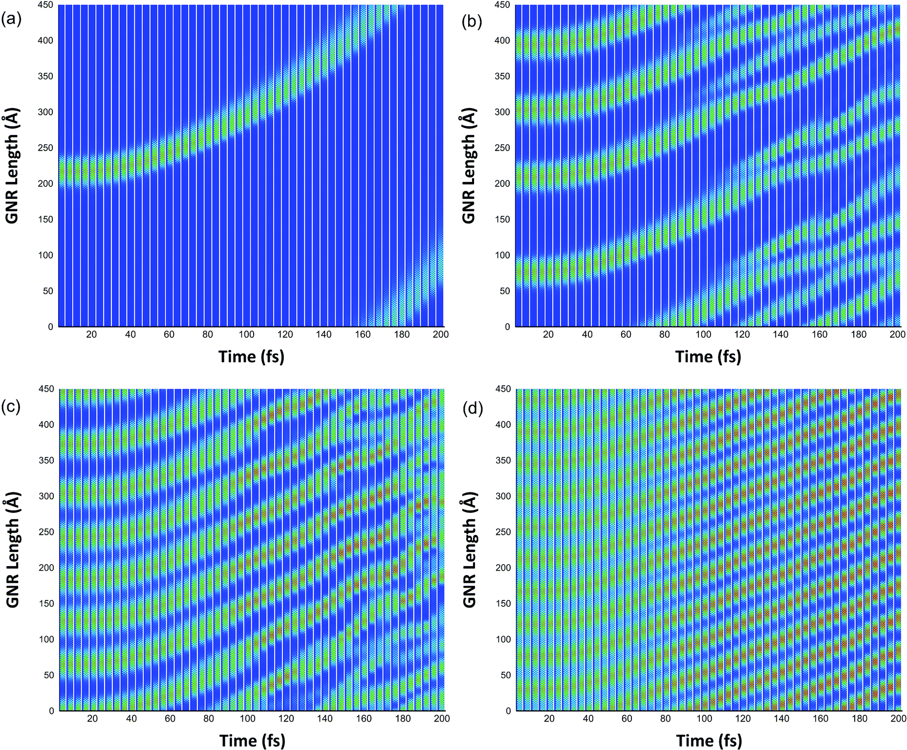 | ||
| Fig. 3 Polaron dynamics for a 4 × 300 AGNR with a 1.2 mV Å−1 electric field and: (a) one polaron, (b) four polarons, (c) seven polarons (d) ten polarons. | ||
As an elucidative way to summarize our results concerning the question of polaron densities, we plot the density of polaron occupation through the nanoribbon's length as a function of the very number of sites in this length. Such density is, therefore, defined as  , where N is the number of polarons, LP is the mean length of each polaron and LC is the length of each chain. One can readily see that for the smallest chain, we could not actually define a polaron for the charge because it is completely displaced throughout the chain's length. As the nanoribbon's length increases, we are able to accommodate more polarons in the system. Because the localization of the quasiparticle increases, one can see that the defined density, i.e., a relative measure of how filled the nanoribbon is, decreases. Naturally, a saturation trend is expected to take place. The figure shows that such an equilibrium is achieved for relative densities smaller than 50% (Fig. 4).
 | ||
| Fig. 4 Polaron density of occupation as a function of the number of sites. | ||
Besides the influence of polarons' density on their own stability, we also investigate its impact on the average velocity of the particles when different electric field intensities are considered. In Fig. 5 we represent the average velocity as a function of the number of polarons in the nanoribbon for several electric field intensities from 0.2 to 2.4 mV Å−1. By analyzing the curves' behavior we can highlight three different regimes, labeled as A, B and C in Fig. 5, and represented by different colors. As higher electric fields correspond to higher velocities, the variation in the average velocity is a more representative quantity to be analyzed. This variation is considerably more pronounced in the region C, where the velocity tends to decrease as the number of polarons increases. This fact is associated with the decrease of the stability. When more than seven polarons are considered, the average velocity decreases approximately linearly. These facts are in agreement with what has been discussed in relation to Fig. 3. This behavior of velocity decreasing is a counterpoint to polaron dynamics in polymeric chains, as it has been shown that the increase in the number of polarons in these systems tends to lead to an increase in the velocity of the quasi-particles.22 In the B region of Fig. 5, the average velocities present much more subtle variations with the increase of the number of polarons. When more than seven polarons are considered, one can note a slight increase of the averaged velocities. Another result of Fig. 5 is the comparison between the polarons’ averaged velocity and the velocity of sound in graphene, found by Vos and coworkers23 to be 0.30 Å fs−1. As shown in Fig. 5, it is only for an electric field of 0.20 mV Å−1 that the average velocities are smaller than the velocity of sound in graphene, characterizing an acoustic regime. In this case the polaron velocity crosses the sound velocity barrier when more than seven polarons are considered. It should be noted that the overcoming of this threshold for seven polarons is responsible for the phase transition discussed in Fig. 3. For other electric fields intensities, shown in the regions B and C, the average velocities of the polarons are greater than the velocity of sound, characterizing an ultrasonic or optical regime. Johansson15 has shown similar results for conjugated polymers where, for low field strength, the polaron velocity is less than the velocity of sound. A transition between these regimes was also observed in that system.
 | ||
| Fig. 5 Average velocities of polarons as a function of the number of polarons with several electric field intensities. | ||
Conclusion
We investigate the importance of polaron density over charge transport for narrow 3p + 1 AGNRs. We employed a two dimensional modified tight-binding model that includes lattice relaxation. After determining a suitable size for our systems, we simulated several different densities and found that, in general, as the density increases, the stability of the polaron decreases. However, for the highest considered densities, specifically for more than seven electrons per 300 sites, a phase transition occurs in the sense of increasing stability by virtue of a collective behavior mediated by mutual polaron interactions. By analyzing the variation of the average velocity of the polarons, one can see that for electric fields greater than 0.6 mV Å−1, the increase of the number of quasi-particles does not cause a considerable variation in their velocities, as we show in region B of Fig. 5. A common result is the linearity of the graphs when more than seven polarons are considered, which corroborates the idea of greater stability in these cases. The different results observed here reinforce the importance of conducting density dependent investigations to obtain a correct and realistic description of charge transport in AGNRs.Conflicts of interest
There are no conflicts to declare.Acknowledgements
The authors gratefully acknowledge the financial support from Brazilian Research Councils CNPq, CAPES, and FAP-DF and CENAPAD-SP for providing the computational facilities. This research work has the support of the Brazilian Ministry of Planning, Development and Management (Grants 005/2016 DIPLA – Planning and Management Directorate, and 11/2016 SEST – State-owned Federal Companies Secretariat) and the DPGU – Brazilian Union Public Defender (Grant 066/2016). L. A. R. J. gratefully acknowledges the financial support from FAP-DF grants 0193.000.942/2015 and 193.001.511/2017.References
- A. K. Geim and K. S. Novoselov, Nat. Mater., 2007, 6, 183 CrossRef PubMed.
- F. Miao, S. Wijeratne, Y. Zhang, U. C. Coskun, W. Bao and C. N. Lau, Science, 2007, 317, 1530 CrossRef PubMed.
- D. Huertas-Hernando, F. Guinea and A. Brataas, Phys. Rev. Lett., 2009, 103, 146801 CrossRef PubMed.
- X. Li, et al. , Science, 2009, 324, 1312 CrossRef PubMed.
- Y. W. Tan, Y. Zhang, K. Bolotin, Y. Zhao, S. Adam, E. H. Hwang, S. D. Sarna, H. L. Stormer and P. Kim, Phys. Rev. Lett., 2007, 99, 246803 CrossRef PubMed.
- K. I. Bolotin, K. J. Sikes, J. Hone, H. L. Stormer and P. Kim, Phys. Rev. Lett., 2008, 101, 096802 CrossRef PubMed.
- P. R. Wallace, Phys. Rev. Lett., 1947, 71, 622 Search PubMed.
- N. Mohanty, D. Moore, Z. Xu, T. S. Spreeprasad, A. Nagaraja, A. A. Rodrigues and V. Berry, Nat. Commun., 2012, 3, 844 CrossRef PubMed.
- W. F. da Cunha, P. H. Acioli, P. H. de Oliveira Neto, R. Gargano and G. M. e Silva, J. Phys. Chem. A, 2016, 120, 4893 CrossRef PubMed.
- W. Ferreira da Cunha, P. H. de Oliveira Neto, A. Terai and G. Magela e Silva, Phys. Rev. B, 2016, 94, 014301 CrossRef.
- P. H. de Oliveira Neto and T. V. Voorhis, Carbon, 2018, 132, 352–358 CrossRef.
- L. A. R. Junior, W. F. da Cunha, A. L. de Almeida Fonseca, R. Gargano and G. M. e Silva, Phys. Chem. Chem. Phys., 2015, 17, 1299–1308 RSC.
- L. A. R. Junior, W. F. da Cunha, A. L. de Almeida Fonseca, G. M. e Silva and S. Stafström, J. Phys. Chem. Lett., 2015, 6, 510–514 CrossRef PubMed.
- A. V. P. Abreu, J. F. Teixeira, A. L. de Almeida Fonseca, R. Gargano, G. M. e Silva and L. A. R. Junior, J. Phys. Chem. A, 2016, 120, 4901–4906 CrossRef PubMed.
- A. A. Johansson and S. Stafstrom, Phys. Rev. B: Condens. Matter Mater. Phys., 2004, 69, 235205 CrossRef.
- J.-L. Bredas and G. B. Street, Acc. Chem. Res., 1985, 18, 309 CrossRef.
- V. N. Kotov, B. Uchoa, V. M. Pereira, F. Guinea and A. H. C. Neto, Rev. Mod. Phys., 2012, 84, 1067 CrossRef.
- J. Yan, Y. Zhang, P. Kim and A. Pinczuk, Phys. Rev. Lett., 2007, 98, 166802 CrossRef PubMed.
- Y. Ono and A. Terai, J. Phys. Soc. Jpn., 1990, 59, 2893 CrossRef.
- L. A. R. Jr., W. F. da Cunha, A. L. de Almeida Fonseca, R. Gargano, G. M. e Silva and S. Stafstrom, J. Phys. Chem. Lett., 2015, 6, 510 CrossRef PubMed.
- P. H. de Oliveira Neto, J. F. Teixeira, W. F. da Cunha, R. Gargano and G. M. e Silva, J. Phys. Chem. Lett., 2012, 3, 3039 CrossRef PubMed.
- P. H. de Oliveira Neto, W. F. da Cunha, R. Gargano and G. M. e Silva, J. Phys. Chem. A, 2009, 113, 14975–14978 CrossRef PubMed.
- F. J. L. Vos, D. P. Aalberts and W. van Saarloos, Phys. Rev. B: Condens. Matter Mater. Phys., 1996, 53(10), R5986–R5989 CrossRef.
| This journal is © the Owner Societies 2018 |