Solvent-controlled synthesis of various Anderson-type polyoxometalate-based metal–organic complexes with excellent capacity for the chromatographic separation of dyes†
Xiu-Li
Wang
 *,
Ge
Song
,
Hong-Yan
Lin
,
Xiang
Wang
,
Guo-Cheng
Liu
and
Xing
Rong
Department of Chemistry, Bohai University, Jinzhou, 121000, P. R. China. E-mail: wangxiuli@bhu.edu.cn; Fax: +86 416 3400158; Tel: +86 416 3400158
First published on 14th November 2017
Abstract
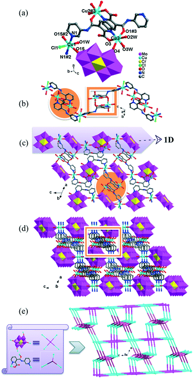
By changing solvent systems, five new Anderson-type polyoxometalates (POMs)-based metal–organic complexes, namely, {(H2PCAP′)2[CrMo6(OH)5O19]}·H2O (1), {Cu3(PCAP)2[CrMo6(OH)5O19](H2O)3(DMF)2}·4H2O·2HCHO (2), {Cu3(PCAP)2[CrMo6(OH)6O18]Cl(H2O)5}·10H2O (3), {Co3(PCAP)2[CrMo6(OH)5O19](H2O)6}·9H2O·HCHO (4) and {Co3(HPCAP)2[CrMo6(OH)6O18]2(H2O)10}·7H2O·2CH3CH2OH (5) (HPCAP = 3-(2-pyridinecarboxylic acid amido)pyridine, PCAP′ = 3-(pyridinecarboxylic acid)amido pyridine), were successfully synthesized and structurally characterized by single-crystal X-ray diffraction, IR spectra, powder X-ray diffraction (PXRD) and thermogravimetric analyses (TGA). Complex 1 was obtained with H2O as the solvent and exhibited a 3D supramolecular network based on CrMo6 anions and protonated H2PCAP′ molecules via hydrogen bonds. It should be noted that the PCAP′ was in situ transformed from HPCAP. Complexes 2–5 were synthesized with different mixed solvents. In complex 2, the CrMo6 anions acted as an inorganic bridging ligand to link the 1D [Cu3(PCAP)2]n4n+ chains to construct a 2D layer. Complexes 3 and 4 showed similar 3D frameworks. Two orientations of metal–organic loops [M2(PCAP)2] (M = Cu for 3, Co for 4) could be observed, which directly extended the 1D M–CrMo6 chains into 3D networks with a 3,3,4,4-connected {42·123·14}{42·6}2 topology. In 5, the 1D Co–CrMo6 inorganic chain, [Co2(PCAP)2] binuclear loop unit and discrete CrMo6 polyanion were connected with each other by hydrogen-bonding interactions to form a 1D ladder-like supramolecular dual chain. The structural diversities showed that the solvents play key roles in the construction of various architectures and in the in situ transformation of HPCAP. The adsorption behaviours of the title complexes for organic dyes were investigated in detail. All of the title complexes showed an efficient adsorption capacity for the cationic dyes gentian violet (GV) and methylene blue (MB). In particular, complex 4 could selectively separate GV from the mixture of GV&RhB and GV&MO within 5–10 min, which can be used as a chromatography column for dye removal. In addition, the electrochemical properties of the title complexes were also studied.
Introduction
As is known, organic dyes have been extensively used in the cotton, spun silk, orlon fibre and linen industries, and even in the paper industry,1–5 but have gradually became a kind of common pollutants in factory sewage due to their toxic, mutagenic and carcinogenic characteristics as well as their transformation products.6 Therefore, it is necessary to find an effective way to deal with organic dyes from dye-wastewater.7 To date, several techniques have been reported for the effective elimination of hazardous substances from wastewater, such as biological treatment,8 chemical oxidation,9 photocatalytic degradation10 and adsorption.11 Among these strategies, adsorption is a promising technology for eliminating dye effluents due to its simpler manipulation, higher efficiency and lower energy depletion.12,13 Until now, a great deal of materials have been developed to adsorb dye-wastewater, such as activated carbon, zeolites, porous organic polymers and MOFs.14 In terms of the various sizes and charges of dyes, the tenable pore size and charge of MOFs make them more suitable to be selected as an adsorption and separation medium.15,16Recently, polyoxometalates (POMs) as a class of metal oxide clusters have attracted tremendous attention in material chemistry due to their wide application potential in the fields of electrochemistry, adsorption, magnetism, catalysis and photochemistry.17–19 Simultaneously, the combination of POMs with transition metal complexes has become a prosperous division, and a great number of POM-based metal organic complexes (MOCs) with intriguing architectures and properties have been obtained.20,21 From the standpoint of their structure, POM anions can be used as excellent inorganic linkages22 or templates23 owing to their abundant O atoms, controllable shapes and sizes and high negative charges. Among the many diverse POMs, the Anderson-type polyoxoanion is an important member in the construction of POM-based MOCs.24,25 Das's group26 and Wang's group27 introduced the Anderson-type [AlMo6(OH)6O18]3−/[CrMo6(OH)6O18]3− polyoxoanions to transition/rare-earth metal complexes, and obtained some extended structures or open-frameworks. Zhou's group also synthesized a series of Anderson-type POM-based MOCs by combining [AlMo6(OH)6O18]3− with nicotinate and lanthanide metals.28 Many Anderson-type POM-based MOCs show remarkable photocatalysis activity towards the decomposition of organic dyes. However, there are few reports on the [CrMo6(OH)6O18]3− (CrMo6)-based MOCs as adsorbents with high uptake capacity and a high selectivity for different organic dyes molecules in the dark at room temperature.29
The organic moieties are crucial for the formation of the desired MOC structures.30–32 Many N-containing ligands have been employed to construct a lot of POM-based MOCs, such as bis(pyridyl)-,33 bis(imidazole)-,34 bis(triazole)-35 and bis(tetrazole)36-based derivative ligands. In our previous work, by using N/O-containing bis-pyridyl-bis-amide ligands, a series of new POM-based complexes were formed.37,38 However, POM-based MOCs constructed from the ligands simultaneously containing pyridyl, amide and carboxyl groups have been rarely reported.39,40 Herein, a pyridyl–carboxylate with an amide group, 3-(2-pyridinecarboxylic acid)amido (HPCAP), was selected as the ligand for assembly with transition metal ions and B-type Anderson-type polyoxoanions (Scheme 1). The HPCAP not only possesses the advantages of pyridyl–amide-based ligands41 but also contains an additional carboxyl group, which can adopt various coordination modes with the pyridyl N, amide O and carboxyl O atoms, and also is conducive to the formation of hydrogen bonds and supramolecular structures. It is worth mentioning that the HPCAP ligand was here introduced into the Anderson-type POM-based MOCs for the first time so far.
In the synthesis process of MOCs, some organic ligands may in situ transform into other one or two new ligands.42 This kind of in situ ligand synthesis under hydrothermal conditions includes C–C bond formation by reductive or oxidative coupling, hydrolysis of the –COOR group, the reduction of –COO– and so on.43–45 Considering the solvent may have a great effect on the assembly and structures of the target MOCs as well as on the in situ ligand transformation, in this work, the HPCAP was used for the assembly with the CrMo6 anion and CuII/CoII ions under different solvent systems. As a result, five Anderson-type POM-based MOCs: {[H2(PCAP′)]2[CrMo6(OH)5O19]}·H2O (1), {Cu3(PCAP)2[CrMo6(OH)5O19](H2O)3(DMF)2}·4H2O·2HCHO (2), {Cu3(PCAP)2[CrMo6(OH)6O18]Cl(H2O)5}·10H2O (3), {Co3(PCAP)2[CrMo6(OH)5O19](H2O)6}·9H2O·HCHO (4) and {Co3(HPCAP)2[CrMo6(OH)6O18]2(H2O)10}·7H2O·2CH3CH2OH (5) were successfully synthesized under hydrothermal or solvothermal conditions. In complex 1, the HPCAP ligand was in situ transformed to the PCAP′ ligand. In addition, the crystals of 4 and 5 could be constructed in one pot. The effects of the solvents and reaction time on the construction of the title complexes are discussed herein. The electrochemical properties and adsorption properties for organic dyes of the title complexes were also studied in detail and discussed herein.
Experimental
Materials and characterization
All the reagents and solvents for the syntheses were purchased from commercial sources and used as received without further purification. The ligand and Na3[CrMo6(OH6)O18]·8H2O were prepared according to the reported procedure.46,47 FT-IR data were taken on a 60 Scimitar 2000 Near FT-IR Spectrometer by using KBr pellets. Elemental analyses of C, H and N were performed on a Perkin Elmer 2400 CHN elemental analyzer, while those of Cu, Co, Cr and Mo were carried out with an Agilent 7500ce Inductively Coupled Plasma (ICP) Mass Spectrometer. Thermogravimetric analyses (TGA) were carried out on a Pyris Diamond TG instrument under a flowing N2 atmosphere with a heating rate of 10 °C min−1. Powder X-ray diffraction (PXRD) patterns were recorded on an Ultima IV with D/teX Ultra diffractometer at 40 kV and 40 mA with CuKα (λ = 1.5406 Å) radiation. A CHI 760 electrochemical workstation was used for the electrochemical experiments at room temperature. UV-vis absorption spectra were obtained using an SP-1901 UV-vis spectrophotometer.X-ray crystallography
Crystallographic data for complexes 1–5 were collected on a Bruker APEX II diffractometer with Mo Kα radiation (λ = 0.71069 Å) in ω and θ scan modes at 293 K. All the structures were solved by direct methods and refined on F2 by full-matrix least squares using the SHELXL package.48 For these complexes, the H atoms on C and N atoms were fixed in the calculated positions. However, in the heavy-atom structures of some of the title complexes, as it was not possible to see clear electron-density peaks in the difference maps that would correspond with acceptable locations for the various H atoms bonded to water oxygen atoms, the refinements were completed with no allowance for these water H atoms in the model, but the missing H atoms of water molecules were directly included in the final molecular formula. The detailed crystal data and structures refinement for 1–5 are given in Table 1. Selected bond lengths and angles are listed in Table S1.† The hydrogen bond parameters of complexes 1–5 are presented in Table S2.† Crystallographic data for the structures reported in this paper have been deposited in the Cambridge Crystallographic Data Centre with CCDC Numbers 1540180, 1540682 and 1540699–1540701 for 1–5, respectively.| Complex | 1 | 2 | 3 | 4 | 5 |
|---|---|---|---|---|---|
| a R 1 = Σ||Fo| – |Fc||/Σ|Fo|. b wR2 = Σ[w(Fo2 – Fc2)2]/Σ[w(Fo2)2]1/2. | |||||
| Empirical formula | C22H28CrMo6N6O27 | C32H53CrCu3Mo6N8O41 | C24H52ClCrCu3Mo6N6O45 | C25H53Co3CrMo6N6O46 | C28H76Co3Cr2Mo12N6O73 |
| Formula weight | 1436.14 | 2024.08 | 1998.42 | 1978.16 | 3097.02 |
| Crystal system | Triclinic | Triclinic | Monoclinic | Triclinic | Triclinic |
| Space group |
P![[1 with combining macron]](https://www.rsc.org/images/entities/char_0031_0304.gif) |
P![[1 with combining macron]](https://www.rsc.org/images/entities/char_0031_0304.gif) |
C 2/c |
P![[1 with combining macron]](https://www.rsc.org/images/entities/char_0031_0304.gif) |
P![[1 with combining macron]](https://www.rsc.org/images/entities/char_0031_0304.gif) |
| a (Å) | 6.021(5) | 9.624(2) | 26.323(2) | 25.9299(17) | 12.3636(5) |
| b (Å) | 12.32(9) | 13.716(4) | 9.8415(9) | 9.8335(6) | 13.0466(5) |
| c (Å) | 13.294(10) | 14.061(3) | 25.627(3) | 24.7101(16) | 14.4949(5) |
| α (°) | 77.871(10) | 61.168(4) | 90 | 90 | 106.0600(10) |
| β (°) | 77.259(10) | 70.680(5) | 117.9220(10) | 117.076 | 97.8180(10) |
| γ (°) | 79.486(10) | 88.297(5) | 90 | 90 | 111.8130(10) |
| V (Å3) | 930.75 (12) | 1515.4(6) | 5865.9(11) | 5610.1(6) | 2009.83(13) |
| Z | 1 | 1 | 4 | 4 | 1 |
| D c (g cm−3) | 2.562 | 2.218 | 2.263 | 2.342 | 2.559 |
| μ (mm−1) | 2.35 | 2.508 | 2.638 | 2.463 | 2.789 |
| F (000) | 694 | 992 | 3912 | 3880 | 1503 |
| Reflection collected | 6844 | 8589 | 16![[thin space (1/6-em)]](https://www.rsc.org/images/entities/char_2009.gif) 311 311 |
19![[thin space (1/6-em)]](https://www.rsc.org/images/entities/char_2009.gif) 751 751 |
14![[thin space (1/6-em)]](https://www.rsc.org/images/entities/char_2009.gif) 801 801 |
| Unique reflections | 4541 | 5309 | 5652 | 6756 | 9866 |
| Parameters | 421 | 492 | 412 | 442 | 618 |
| R int | 0.0142 | 0.0307 | 0.0474 | 0.0444 | 0.0144 |
| GOF | 1.036 | 1.001 | 1.032 | 1.013 | 1.045 |
| R 1 [I > 2σ(I)] | 0.023 | 0.0547 | 0.0388 | 0.034 | 0.0285 |
| wR2b (all data) | 0.0559 | 0.1641 | 0.1000 | 0.0719 | 0.0751 |
Preparation of complexes 1–5
![[thin space (1/6-em)]](https://www.rsc.org/images/entities/char_2009.gif) :
:![[thin space (1/6-em)]](https://www.rsc.org/images/entities/char_2009.gif) v = 1
v = 1![[thin space (1/6-em)]](https://www.rsc.org/images/entities/char_2009.gif) :
:![[thin space (1/6-em)]](https://www.rsc.org/images/entities/char_2009.gif) 1
1![[thin space (1/6-em)]](https://www.rsc.org/images/entities/char_2009.gif) :
:![[thin space (1/6-em)]](https://www.rsc.org/images/entities/char_2009.gif) 3) was added in a Teflon-lined autoclave (25 mL) and heated at 85 °C for 4 days. After slow cooling to room temperature, green block crystals of 2 were obtained and washed off the green precipitate with distilled water, then dried in a desiccator at room temperature to give a yield of 35% based on Mo. Anal. calcd (found %) for 2: C, 18.98 (18.00); H, 2.63 (2.42); N, 5.53 (5.32); Cu, 9.42 (9.52); Cr, 2.57 (2.93); Mo, 28.44 (30.12). IR (KBr pellet, cm−1): 3439(s), 2361(m), 1653(s), 1527(m), 1434(w), 1346(m), 1110(w), 895(s), 650(s).
3) was added in a Teflon-lined autoclave (25 mL) and heated at 85 °C for 4 days. After slow cooling to room temperature, green block crystals of 2 were obtained and washed off the green precipitate with distilled water, then dried in a desiccator at room temperature to give a yield of 35% based on Mo. Anal. calcd (found %) for 2: C, 18.98 (18.00); H, 2.63 (2.42); N, 5.53 (5.32); Cu, 9.42 (9.52); Cr, 2.57 (2.93); Mo, 28.44 (30.12). IR (KBr pellet, cm−1): 3439(s), 2361(m), 1653(s), 1527(m), 1434(w), 1346(m), 1110(w), 895(s), 650(s).
![[thin space (1/6-em)]](https://www.rsc.org/images/entities/char_2009.gif) :
:![[thin space (1/6-em)]](https://www.rsc.org/images/entities/char_2009.gif) v = 1
v = 1![[thin space (1/6-em)]](https://www.rsc.org/images/entities/char_2009.gif) :
:![[thin space (1/6-em)]](https://www.rsc.org/images/entities/char_2009.gif) 1). After slow cooling to room temperature, blue block crystals of 3 were filtered and washed off the blue precipitate with distilled water, and then dried at room temperature in a desiccator, giving a yield of 41% based on Mo. Anal. calcd (found %) for 3: C, 14.43 (14.41); H, 2.62 (2.61); N, 4.21 (4.13); Cu, 9.54 (9.69); Cr, 2.61 (2.96); Mo, 28.81 (30.64). IR (KBr pellet, cm−1): 3411(m), 3221(w), 2367(w), 1645(s), 1571(s), 1489(m), 1398(m), 1290(m), 948(s), 669(s).
1). After slow cooling to room temperature, blue block crystals of 3 were filtered and washed off the blue precipitate with distilled water, and then dried at room temperature in a desiccator, giving a yield of 41% based on Mo. Anal. calcd (found %) for 3: C, 14.43 (14.41); H, 2.62 (2.61); N, 4.21 (4.13); Cu, 9.54 (9.69); Cr, 2.61 (2.96); Mo, 28.81 (30.64). IR (KBr pellet, cm−1): 3411(m), 3221(w), 2367(w), 1645(s), 1571(s), 1489(m), 1398(m), 1290(m), 948(s), 669(s).
![[thin space (1/6-em)]](https://www.rsc.org/images/entities/char_2009.gif) :
:![[thin space (1/6-em)]](https://www.rsc.org/images/entities/char_2009.gif) v = 1
v = 1![[thin space (1/6-em)]](https://www.rsc.org/images/entities/char_2009.gif) :
:![[thin space (1/6-em)]](https://www.rsc.org/images/entities/char_2009.gif) 1). After slow cooling to room temperature, orange block crystals of 4 and pink block crystals of 5 were obtained and washed off the pink precipitate with distilled water, and then dried in a desiccator at room temperature to give a yield of 18% for 4 and 27% for 5 based on Mo. Anal. calcd (found %) for 5: C, 10.85 (9.35); H, 2.47 (2.48); N, 2.71 (2.80); Co, 5.70 (6.29); Cr, 3.36 (3.74); Mo, 37.17 (38.99). IR (KBr pellet, cm−1): 3414(s), 2923(w), 2360(s), 1584(s), 1430(m), 1371(s), 1103(m), 914(s), 653(s).
1). After slow cooling to room temperature, orange block crystals of 4 and pink block crystals of 5 were obtained and washed off the pink precipitate with distilled water, and then dried in a desiccator at room temperature to give a yield of 18% for 4 and 27% for 5 based on Mo. Anal. calcd (found %) for 5: C, 10.85 (9.35); H, 2.47 (2.48); N, 2.71 (2.80); Co, 5.70 (6.29); Cr, 3.36 (3.74); Mo, 37.17 (38.99). IR (KBr pellet, cm−1): 3414(s), 2923(w), 2360(s), 1584(s), 1430(m), 1371(s), 1103(m), 914(s), 653(s).
Results and discussion
Structural description
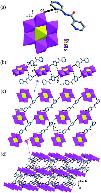
The [CrMo6(OH)6O18]3−(CrMo6) anions acting as the inorganic ligands display various coordination modes in complexes 1–5, which show a B-type Anderson structure made up of seven edge-sharing octahedra. The coordination modes of the CrMo6 anions in 1–5 are shown in Table 2. Furthermore, the valence sum calculations showed that all the Mo atoms were in the +VI oxidation state.In complex 1, a pair of H2PCAP′ molecules bridge two neighbouring CrMo6 anions via C–H⋯O hydrogen-bonding interactions between C atoms (C2 and C4) from H2PCAP′ and O atoms (O5 and O7) from CrMo6 anions to generate a 1D supramolecular chain (Fig. 1b). The distances are 3.152 Å for C2–H2A⋯O5 and 3.046 Å for C4–H4A⋯O7. The H2PCAP′ further links adjacent chains via hydrogen-bonding interactions [C10–H10A⋯O12, 3.332 Å] to form a 2D supramolecular layer (Fig. 1c). Ultimately, the adjacent 2D layers are further joined together through C–H⋯O hydrogen-bonding interactions [C11–H11A⋯O1, 3.238 Å] to construct a 3D supramolecular framework (Fig. 1d).
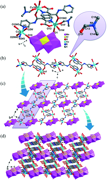
In 2, two crystallographically independent CuII ions are connected by PCAP ligands with the μ3-bridging mode (utilizing its two pyridyl N atoms, one amide O atom and one carboxyl O atom, Table 2) to give a bunch-like [Cu3(PCAP)2]n4n+ chain (Fig. 2b). In the 1D chain, two Cu1 ions are bridged by two PACP ligands to give a binuclear loop with the size of 6.480 × 6.143 Å2 (Fig. S1†). Furthermore, the CrMo6 anion utilizes its four terminal O atoms as a tetradentate linkage (Table 2) to coordinate with four CuII ions from two adjacent 1D chains, thus the 2D layer of compound 2 is generated (Fig. 2c). A detailed structural analysis reveals that the adjacent 2D layers are finally linked via C–H⋯O hydrogen bonds [C(3)–H(3A)⋯O(6), 3.287 Å] between the carbon atom and the oxygen atom from PCAP forming a 3D supramolecular network (Fig. 2d).
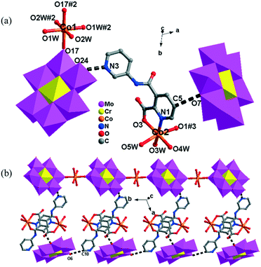
There are two crystallographically independent CoII ions in 5, in which the Co1 ion is six-coordinated, defined by four O atoms from four coordinated water molecules and two O atoms from two CrMo6 polyoxoanions. The bond distances around the Co1 ion are 2.043(3)–2.091(3) Å for Co–O, and the bond angles are 89.18(2)–180(5)° for O–Co–O. The Co2 ion is also six-coordinated by one N atom, two O atoms from two HPCAP ligands and three O atoms from three water molecules. The bond lengths and angles around the Co2 ion are 2.131(3) Å for Co–N, 2.016(3)–2.222(3) Å for Co–O and the bond angles are 77(1)–161.67(13)° for O–Co–N and 82.6(12)–167.53(10)° for O–Co–O.
In 5, the Co1 ion bridges two neighbouring CrMo6 anions to form a Co–CrMo6 inorganic chain, while two Co2 ions are connected by two PCAP ligands with two carboxyl O atoms, two pyridyl N atoms and two amide O atoms from two PCAP ligands to form a [Co2(HPCAP)2]4+ binuclear unit (Fig. S1†). It should be noted that the other pyridyl N atom of PCAP was protonated and noncoordinated to CoII ions. The binuclear units are connected with the CrMo6 anions from the 1D chain and the discrete CrMo6 anion through hydrogen-bonding interactions [N3–H3A⋯O24, 2.752 Å], [C5–H5A⋯O7, 3.119 Å] and [C(10)–H(10A)⋯O(6), 3.188 Å] to construct a 1D ladder-like supramolecular chain (Fig. 4b).
The influence of the solvents, reaction time and ligands on the synthesis and structures of the title complexes
The synthesis of POM-based MOCs is always uncontrollable because many subtle factors can affect their assembly. In this work, by using different solvents (DMF, MeOH, EtOH and H2O) under similar reaction conditions, five different complexes 1–5 were synthesized (Scheme 2). When employing H2O as a solvent, though various metal ions (Cu, Co, Cd, Zn, etc.) were tried to be introduced into the system of 1, only the supramolecular structure of 1 without a metal could be obtained. Different from 1, complexes 2–5 were successfully obtained in the diverse solvents-H2O mixed systems. Notably, the HPCAP ligand was in situ transformed to the PCAP′ ligand only in complex 1, which may be due to the different solvent systems. Both 2 and 3 are CuII complexes, where the 2D metal–organic layered structure 2 could be obtained when the mixed solvent of DMF–EtOH–H2O [v![[thin space (1/6-em)]](https://www.rsc.org/images/entities/char_2009.gif) :
:![[thin space (1/6-em)]](https://www.rsc.org/images/entities/char_2009.gif) v
v![[thin space (1/6-em)]](https://www.rsc.org/images/entities/char_2009.gif) :
:![[thin space (1/6-em)]](https://www.rsc.org/images/entities/char_2009.gif) v = 2
v = 2![[thin space (1/6-em)]](https://www.rsc.org/images/entities/char_2009.gif) :
:![[thin space (1/6-em)]](https://www.rsc.org/images/entities/char_2009.gif) 2
2![[thin space (1/6-em)]](https://www.rsc.org/images/entities/char_2009.gif) :
:![[thin space (1/6-em)]](https://www.rsc.org/images/entities/char_2009.gif) 6] was used, and then the 2D layers were further extended to a 3D supramolecular framework through hydrogen-bonding interactions. Nevertheless, when the mixture solvent of MeOH and H2O (v
6] was used, and then the 2D layers were further extended to a 3D supramolecular framework through hydrogen-bonding interactions. Nevertheless, when the mixture solvent of MeOH and H2O (v![[thin space (1/6-em)]](https://www.rsc.org/images/entities/char_2009.gif) :
:![[thin space (1/6-em)]](https://www.rsc.org/images/entities/char_2009.gif) v = 1
v = 1![[thin space (1/6-em)]](https://www.rsc.org/images/entities/char_2009.gif) :
:![[thin space (1/6-em)]](https://www.rsc.org/images/entities/char_2009.gif) 1) was selected, complex 3 with a 3D metal–organic framework structure was formed. Similarly, two Co(II) complexes of 4 and 5 were obtained in the mixed solvent of DMF–EtOH–H2O [v
1) was selected, complex 3 with a 3D metal–organic framework structure was formed. Similarly, two Co(II) complexes of 4 and 5 were obtained in the mixed solvent of DMF–EtOH–H2O [v![[thin space (1/6-em)]](https://www.rsc.org/images/entities/char_2009.gif) :
:![[thin space (1/6-em)]](https://www.rsc.org/images/entities/char_2009.gif) v
v![[thin space (1/6-em)]](https://www.rsc.org/images/entities/char_2009.gif) :
:![[thin space (1/6-em)]](https://www.rsc.org/images/entities/char_2009.gif) v = 2
v = 2![[thin space (1/6-em)]](https://www.rsc.org/images/entities/char_2009.gif) :
:![[thin space (1/6-em)]](https://www.rsc.org/images/entities/char_2009.gif) 2
2![[thin space (1/6-em)]](https://www.rsc.org/images/entities/char_2009.gif) :
:![[thin space (1/6-em)]](https://www.rsc.org/images/entities/char_2009.gif) 6] and EtOH–H2O [v
6] and EtOH–H2O [v![[thin space (1/6-em)]](https://www.rsc.org/images/entities/char_2009.gif) :
:![[thin space (1/6-em)]](https://www.rsc.org/images/entities/char_2009.gif) v = 1
v = 1![[thin space (1/6-em)]](https://www.rsc.org/images/entities/char_2009.gif) :
:![[thin space (1/6-em)]](https://www.rsc.org/images/entities/char_2009.gif) 1], respectively. Complex 4 has a similar 3D framework to 3, while 5 is a 1D chain structure. It's worth mentioning that we could not harvest any crystal of 4 when the solvent system was the same as that of 3. These results indicate that the solvents not only can influence the assembly and final structures, but also play an important role in inducing in situ transformation of the ligand in this system.
1], respectively. Complex 4 has a similar 3D framework to 3, while 5 is a 1D chain structure. It's worth mentioning that we could not harvest any crystal of 4 when the solvent system was the same as that of 3. These results indicate that the solvents not only can influence the assembly and final structures, but also play an important role in inducing in situ transformation of the ligand in this system.
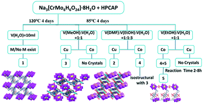 | ||
| Scheme 2 Schematic illustrations of the effect of different solvents, the reaction time and metal ions on the structures of complexes 1–5. | ||
In the synthetic process of complexes 4 and 5, there was also an interesting phenomenon. Both 4 and 5 could be simultaneously obtained in the mixed solvent of EtOH and H2O. Notably, the significantly different colours of these two complexes is a benefit for distinguishing their crystals (Fig. 5a and b). In order to get pure crystal products, several factors associated with their synthesis, such as temperature, reactant ratios, the mixed solvent and reaction time, were tested. Fortunately, we found that the formation of the products 4 and 5 mainly depended on the reaction time. As shown in Fig. 5c–h, with increasing the reaction time, pink crystals of 5 were first observed at 2 h, while orange crystalline 4 began to form at 8 h, and products of 4 and 5 gradually increased in the reaction time range of 2–96 h. It can thus be concluded that the reaction time was the crucial factor to prepare 4 and 5.
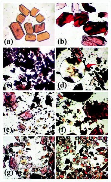 | ||
| Fig. 5 Optical micrograph of complexes 4 (a) and 5 (b). Yields of 4 and 5 at the reaction time: 2 h (c); 8 h (d); 16 h (e), 24 h (f); 48 h (g); 96 h (h). | ||
In addition, in this paper, parallel experiments revealed that temperature and metal ions also influence the synthesis. We could not harvest any products of 1–5 when the heating temperature was altered. For complex 1, the addition of metal ions could increase the yield of crystals, which suggests that the metal ions may act as a catalyst in this reaction system. Compared with other metal ions, the yield of 1 reached the highest level when ZnCl2 was added into the reaction system as the initial reactant.
In our previous work, we obtained three octamolybdate-based MOCs with a similar pyridyl–carboxylate amide ligand HPPA (6-(pyridine-3-ylcarbamoyl)picolinic acid) under solvothermal conditions.39 These complexes exhibited 0D or 1D structures. Alternatively, we tried to prepare other new POM-based MOCs by combining HPPA with different polyanions (such as Anderson-type anions), but no crystals could be obtained under similar or even other reaction conditons. Based on these results, could the higher dimensional POM-based MOCs be obtained by using positional isomers of the ligands? With this in mind, the ligand HPCAP with a 2,3-substituted pyridyl ring was used in this work. Fortunately, we obtained five complexes with Anderson-type POMs, which showed diverse structures from 0D to 3D frameworks. The results strongly suggested that the coordination sites of the isomeric organic ligands have an essential influence on the title complexes. Moreover, five different complexes 1–5 were synthesized under similar reaction conditions by using different solvents (DMF, MeOH, EtOH and H2O) (Scheme 2), while only the methanol–water mixed solvent was used in the previous work.39
IR spectra
The IR spectra of the title complexes are shown in Fig. S3.†The characteristic bands observed at 696 and 919 cm−1 for 1, 650 and 895 cm−1 for 2, 669 and 948 cm−1 for 3, 657 and 898 cm−1 for 4 and 653 and 914 cm−1 for 5 are attributed to ν(Mo–O) and ν(Mo–O–Mo), respectively.51 The characteristic bands at 1399 and 1625 cm−1 for 1, 1346 and 1653 cm−1 for 2, 1290 and 1645 cm−1 for 3, 1358 and 1659 cm−1 for 4 and 1371 and 1584 cm−1 for 5 are due to the PCAP′ or HPCAP ligands.52 The bands around 3400 cm−1 can be ascribed to the water molecules.
Powder X-ray diffraction (PXRD) and thermal analyses
The powder X-ray diffraction (PXRD) patterns of complexes 1–5 are shown in Fig. S4† for determining the purity of the crystalline phase. We can observe that the diffraction peaks of the synthesized complexes match well with the simulated ones, besides some intensity differences, which may be due to the different orientations of the crystals in the powder samples.53Thermogravimetric analyses (TGA) of the complexes 1–5 were performed under a flowing N2 atmosphere with a heating rate of 10 °C min−1 from room temperature to 800 °C (Fig. S5†).The TG curves of 1–5 reveal a first weight loss of 1.74% for 1, 15.65% for 2, 14.3% for 3, 15.79% for 4 and 13.46% for 5 at 147–251 °C, corresponding to the loss of the coordinated/lattice water molecules (calcd: 1.25%, 15.23%, 13.51%, 15.82% and 12.67%), respectively. After that, a further weight loss for 1–5 was observed at 279–488 °C, representing the framework beginning to decompose.
Electrochemical behaviours of complex 3
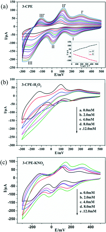
In order to investigate the electrochemical properties of these complexes, the title complexes bulk-modified CPEs were fabricated and used, owing to their insolubility in water and common organic solvents. Because the electrochemical behaviours of the title complexes are similar apart from some light potential shift, complex 3 is taken here as an example. The electrochemical behaviours of complex 3 bulk-modified carbon paste electrode (3-CPE) in 0.1 M H2SO4 + 0.5 M Na2SO4 aqueous solution at different scan rates are presented in Fig. 6a.Three pairs of reversible redox peaks were observed. The mean peak potentials E1/2 = (Epa + Epc)/2 were 267 mV (I–I′), 32 mV (II–II′) and −149 mV (III–III′), which belong to the two-electron redox processes of Mo centres of CrMo6 polyanions.54 The peak potentials change gradually with increasing the scan rates; whereby, the cathodic peak potentials shift towards the negative direction and the corresponding anodic peak potentials shift to the positive direction (Fig. 6a). The peak currents are proportional to the scan rates up to 500 mV s−1, indicating that the redox process of the 3-CPE is surface-controlled.55
It is well known that POMs usually show active electrocatalytic properties in the reduction process of peroxide, nitrite and other substances in aqueous solution.56 In this paper, we also investigated the electrocatalytic activities of 3-CPE towards the reduction of hydrogen peroxide and nitrite. As can be seen from Fig. 6b and c, with the addition of nitrite and hydrogen peroxide, the reduction peak currents of 3-CPE increase gradually and the corresponding oxidation peak currents gradually decrease. Alternatively, no obvious voltammetry response was observed at the bare CPE in the presence of hydrogen peroxide and nitrite in the same potential range, suggesting that the reduced species of the CrMo6 anions in 3 possess electrocatalytic activity for the reduction of H2O2 and KNO2.
Adsorption properties for organic dyes
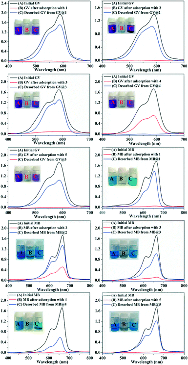
In recent years, some POM-based organic–inorganic hybrids have been reported for the adsorption of organic dyes.39,57 With this in mind, four organic dyes: methylene blue (MB), gentian violet (GV), methyl orange (MO) and rhodamine B (RhB) were selected as the model pollutants to evaluate the adsorption behaviours of complexes 1–5 at room temperature. These dyes features different size and charges (Table S3 and Scheme S1†). The adsorption performance was investigated through a typical process: 50 mg powder of 1–5 was dispersed in MB/GV/MO/RhB solutions (10 mg L−1, 100 mL) and stirred in the dark at room temperature, respectively. Then, the supernatant of the MB/GV/MO/RhB solution was taken out for analysis at regular time intervals. As shown in Fig. 7, a similar phenomenon could be observed obviously for GV, where the violet solution turned to colourless within 10 min, and the corresponding absorption peaks decreased rapidly, indicating that 1–5 all have excellent adsorption ability for GV dye. The adsorption ratio of GV is roughly 99.72% for 1, 97.63% for 2, 97.72% for 3, 99.91% for 4 and 99.94% for 5 (Fig. S6,†Table 3). As for MB, with increasing the adsorption time for complexes 1–5, colour fading of the blue solution was clearly observed by the naked eye within 30 min for 1, 4 and 5 and 150 min for 2 and 3 (Fig. 8). Also, the maximum per cent adsorption of MB was roughly 97.7% for 1, 70.6% for 2, 94.1% for 3, 97.1% for 4 and 97.5% for 5 within 150 min (Fig. S7,†Table 3). These different results may be due to the different structures of 1–5. However, the title complexes had no obvious adsorption effect for MO and RhB (Fig. S8 and S9†). This phenomenon seems to be related to the different charges and molecular sizes of the selected organic dyes.39,58,59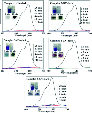 | ||
| Fig. 7 Absorption spectra of the GV solution during the adsorption process in the presence of complexes 1–5. | ||
| Adsorption rate % | GV 10 min | MB 150 min | MO 150 min | RhB 150 min |
|---|---|---|---|---|
| 1 | 99.7 | 97.7 | 10.8 | 11.2 |
| 2 | 97.6 | 70.6 | 14.6 | 4.4 |
| 3 | 97.7 | 94.1 | 12.25 | 5.2 |
| 4 | 99.9 | 97.1 | 13.8 | 12.2 |
| 5 | 99.9 | 97.5 | 12.16 | 5.8 |
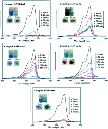 | ||
| Fig. 8 Absorption spectra of the MB solution during the adsorption process in the presence of complexes 1–5. | ||
The adsorption amounts qt (mg g−1) of dyes GV and MB by 1–5 are listed in Table 4 as calculated by: qt = (C0 − Ct) V/W, where, C0 and Ct (mg L−1) are the liquid phase concentration of dyes at the beginning and after a given time t (min), respectively, V (L) is the volume of the solution and W (g) is the mass of the sample used (Table 4).60
| Adsorption quantity (mg g−1) | GV 10 min | MB 150 min |
|---|---|---|
| 1 | 19.96 | 19.44 |
| 2 | 19.91 | 13.19 |
| 3 | 19.48 | 18.59 |
| 4 | 19.95 | 19.29 |
| 5 | 19.93 | 19.33 |
After the adsorption experiments, dye-releasing experiments were executed in pure DMF, pure acetonitrile, NaCl-containing DMF and NaCl-containing acetonitrile solution, respectively. The results showed that the release process could be monitored in all four eluting solutions and the dye molecules could be immediately washed off using a solution of NaCl with acetonitrile. As shown in Fig. 9, the colourless solution quickly changes to violet or blue with the UV-vis absorption intensity of GV/MB increasing in the NaCl-containing acetonitrile solution.
Chromatography column of 4 for dye removal
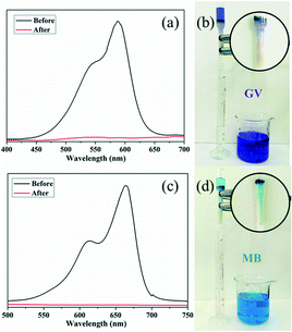
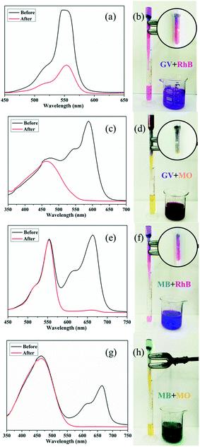
A fast adsorption rate is an important parameter to evaluate the practicability and efficiency of an adsorbent in an economical wastewater disposal system, in which an adsorbent material can remove the target dyes rapidly. On the other hand, the selective uptake of organic dyes is more attractive and challenging. Fortunately, almost all of the title complexes showed excellent adsorption capabilities with GV. Thus, complex 4 was selected as an example for its outstanding performance and relatively higher yield. First, homemade columns with samples of 4 were used to examine its performance in a fast adsorption. As shown in Fig. 10, when the solution of GV or MB passed through the 4-packed column, a colourless effluent was observed, while the color of crystals in the top part of the column was changed, indicating that the dye molecules were captured by the samples of 4. The UV-vis spectrum was measured to further detect the concentration of dye molecules in the effluent. As shown in Fig. 10, the dye molecules were removed completely by the crystals of 4 in the passing-through process. Then, the mixtures of dyes (GV&RhB, GV&MO and MB&RhB, MB&MO) were prepared for investigation of the selective uptake of organic dyes using samples of 4. As shown in Fig. 11, when the dye mixture GV&RhB or GV&MO and MB&RhB or MB&MO passed through the 4-packed column, it was clearly observed that GV and MB molecules were captured at the top part of the column, while the RhB and MO molecules passed through the column. Again the effluent colour could be monitored not only by the naked eye but also by the UV-vis spectra. The successful uptake, capture and separation of organic dyes by 4 indicated that it was a very definite possibility for the title complexes to be a suitable choice to adsorb and separate organic dye pollutants.Conclusions
In summary, by controlling the solvent systems, five new CrMo6-based MOCs with different structures were successfully assembled. The solvents and reaction time had a great effect on the formation of the final architectures. The title complexes could effectively adsorb the organic dyes MB and GV, especially complexes 1, 4 and 5, which could selectively separate MB and GV from the mixtures of GV&RhB, GV&MO and MB&RhB, MB&MO for a moment, respectively. The results of the adsorption and separation of organic dyes will expand the application of this kind of POM-based complexes.Conflicts of interest
There are no conflicts to declare.Acknowledgements
The supports of the National Natural Science Foundation of China (No. 21671025, 21501013, 21471021, 21401010) and Program for Distinguished Professor of Liaoning Province (No. 2015399) are gratefully acknowledged.Notes and references
- I. D. Rattee, Chem. Soc. Rev., 1972, 1, 145 RSC.
- M. Liang and J. Chen, Chem. Soc. Rev., 2013, 42, 3453 RSC.
- W. N. Jones, Chem. Rev., 1945, 36, 291 CrossRef CAS.
- M. Q. Doja, Chem. Rev., 1932, 11, 273 CrossRef CAS.
- V. Jabbaria, J. M. Veleta, M. Zarei-Chaleshtoric, J. Gardea-Torresdey and D. Villagrán, Chem. Eng. J., 2016, 304, 774 CrossRef.
- H. Zhang, D. Chen, X. J. Lv, Y. Wang, H. X. Chang and J. H. Li, Environ. Sci. Technol., 2010, 44, 1107 CrossRef CAS PubMed.
- F. Y. Yi, W. Zhu, S. Dang, J. P. Li, D. Wu, Y. H. Li and Z. M. Sun, Chem. Commun., 2015, 51, 3336 RSC.
- N. Daneshvar, M. Ayazloo, A. R. Khataee and M. Pourhassan, Bioresour. Technol., 2007, 98, 1176 CrossRef CAS PubMed.
- W. Chen, W. Lu, Y. Yao and M. Xu, Environ. Sci. Technol., 2007, 41, 6240 CrossRef CAS PubMed.
- G. Zhao, L. J. Liu, J. R. Li and Q. Liu, J. Alloys Compd., 2016, 664, 169 CrossRef CAS.
- A. X. Yan, S. Yao, Y. G. Li, Z. M. Zhang, Y. Lu, W. L. Chen and E. B. Wang, Chem. – Eur. J., 2014, 20, 6927 CrossRef CAS PubMed.
- P. Fei, Q. Wang, M. Zhong and B. Su, J. Alloys Compd., 2016, 685, 411 CrossRef CAS.
- H. Wang, H. Gao, M. Chen, X. Xu, X. Wang, C. Pan and J. Gao, Appl. Surf. Sci., 2016, 360, 840 CrossRef CAS.
- X. Zhao, X. Bu, T. Wu, S. T. Zheng, L. Wang and P. Feng, Nat. Commun., 2013, 4, 2344 Search PubMed.
- P. Li, N. A. Vermeulen, X. R. Gong, C. D. Malliakas, J. F. Stoddart, J. T. Hupp and O. K. Farha, Angew. Chem., 2016, 128, 10514 CrossRef.
- A. Karmakar, A. V. Desai and S. K. Ghosh, Coord. Chem. Rev., 2016, 307, 313 CrossRef CAS.
- H. Miao, H. X. Wan, M. Liu, Y. Zhang, X. Xu, W. W. Ju, D. R. Zhu and Y. Xu, J. Mater. Chem. C, 2014, 2, 6554 RSC.
- X. K. Fang, P. Kogerler, L. Isaacs, S. Uchida and N. Mizuno, J. Am. Chem. Soc., 2009, 131, 432 CrossRef CAS PubMed.
- M. Ibrahim, Y. H. Lan, B. S. Bassil and Y. X. Xiang, Angew. Chem., Int. Ed., 2011, 50, 4708 CrossRef CAS PubMed.
- Y. Zhang, J. Q. Shen, L. H. Zheng, Z. M. Zhang, Y. X. Li and E. B. Wang, Cryst. Growth Des., 2014, 14, 110 CAS.
- S. T. Zheng, J. Zhang, J. M. Clemente-Juan, D. Q. Yuan and G. Y. Yang, Angew. Chem., Int. Ed., 2009, 48, 7176–7179 CrossRef CAS PubMed.
- A. Yokoyama, T. Kojima, K. Ohkubo and S. Fukuzumi, Chem. Commun., 2007, 3997 RSC.
- F. J. Ma, S. X. Liu, C. Y. Sun, D. D. Liang, G. J. Ren, F. Y. Wei, G. Chen and Z. M. Su, J. Am. Chem. Soc., 2011, 133, 4178 CrossRef CAS PubMed.
- J. S. Anderson, Nature, 1937, 140, 850 CrossRef CAS.
- H. T. Evans, Acta Crystallogr., Sect. B: Struct. Crystallogr. Cryst. Chem., 1974, 30, 2095 CrossRef.
- V. Shivaiah, M. Nagaraju and S. K. Das, Inorg. Chem., 2003, 42, 6604 CrossRef CAS PubMed.
- H. Y. An, D. R. Xiao, E. B. Wang, Y. G. Li, X. L. Wang and L. Xu, Eur. J. Inorg. Chem., 2005, 2005, 854 CrossRef.
- H. Y. Ji, X. M. Li, D. H. Xu, Y. S. Zhou and L. J. Zhang, Inorg. Chem., 2017, 56, 156 CrossRef CAS PubMed.
- X. L. Wang, J. J. Sun, H. Y. Lin, Z. H. Chang, G. C. Liu and X. Wang, RSC Adv., 2016, 6, 110583 RSC.
- J. X. Meng, Y. Lu, Y. G. Li, H. Fu and E. B. Wang, Cryst. Growth Des., 2009, 9, 4116 CAS.
- P. P. Zhang, J. Peng, H. J. Pang, J. Q. Sha, M. Zhu, D. D. Wang, M. G. Liu and Z. M. Su, Cryst. Growth Des., 2011, 11, 2736 CAS.
- X. L. Wang, H. L. Hu and A. X. Tian, Cryst. Growth Des., 2010, 10, 4786 CAS.
- B. K. Tripuramallu and S. K. Das, Cryst. Growth Des., 2013, 13, 2426 CAS.
- Y. Q. Lan, S. L. Li, X. L. Wang, K. Z. Shao, D. Y. Du, H. Y. Zang and Z. M. Su, Inorg. Chem., 2008, 47, 8179 CrossRef CAS PubMed.
- J. Q. Sha, M. T. Li, J. W. Sun, Y. N. Zhang, P. F. Yan and G. M. Li, Dalton Trans., 2013, 42, 7803 RSC.
- X. L. Wang, H. L. Hu, G. C. Liu, H. Y. Lin and A. X. Tian, Chem. Commun., 2010, 46, 6485 RSC.
- X. L. Wang, J. J. Sun, H. Y. Lin, Z. H. Chang, A. X. Tian, G. C. Liu and X. Wang, Dalton Trans., 2016, 45, 2709 RSC.
- X. L. Wang, Z. H. Chang, H. Y. Lin, C. Xu, J. Luan, G. C. Liu and A. X. Tian, RSC Adv., 2015, 5, 35535 RSC.
- X. L. Wang, X. Rong, D. N. Liu, H. Y. Lin, X. Wang, G. C. Liu and G. Song, Polyhedron, 2017, 126, 92 CrossRef CAS.
- X. L. Wang, D. N. Liu, H. Y. Lin, G. C. Liu, X. Wang, M. Le and X. Rong, CrystEngComm, 2016, 18, 888 RSC.
- X. L. Wang, J. Luan, F. F. Sui, H. Y. Lin, G. C. Liu and C. Xu, Cryst. Growth Des., 2013, 13, 3561 CAS.
- X. M. Chen and M. L. Tong, Acc. Chem. Res., 2007, 40, 162 CrossRef CAS PubMed.
- C. M. Liu, S. Gao and H. Z. Kou, Chem. Commun., 2001, 1670 RSC.
- W. B. Lin, Z. Y. Wang and L. Ma, J. Am. Chem. Soc., 1999, 121, 11249 CrossRef CAS.
- Y. H. Feng, Z. G. Han, J. Peng and X. R. Hao, J. Mol. Struct., 2005, 734, 171 CrossRef CAS.
- J. S. Goldsworthy, A. L. Pochodylo and R. L. LaDuca, Inorg. Chim. Acta, 2014, 419, 26 CrossRef CAS.
- K. Nomiya, T. Takahashi and T. Shirai, Polyhedron, 1987, 6, 213 CrossRef CAS.
- G. M. Sheldrick, Acta Crystallogr., Sect. A: Found. Crystallogr., 2008, 64, 112 CrossRef CAS PubMed.
- Y. Z. Zheng, M. L. Tong and X. M. Chen, New J. Chem., 2004, 28, 1412 RSC.
- A. Rossin, A. Ienco, F. Costantino, T. Montini, B. Di Credico, M. Caporali, L. Gonsalvi, P. Fornasiero and M. Peruzzini, Cryst. Growth Des., 2008, 8, 3302 CAS.
- M. Yu, B. Gao and D. D. Liang, J. Cluster Sci., 2014, 25, 377 CrossRef CAS.
- H. Erer, O. Z. Yesilel and M. Arıcı, Cryst. Growth Des., 2015, 15, 3201 CAS.
- A. Z. Tian, J. Ying, J. Peng, J. Q. Sha, H. J. Pang, P. P. Zhang, Y. Chen, M. Zhu and Z. M. Su, Cryst. Growth Des., 2008, 8, 3717 CAS.
- C. H. Gong, X. H. Zeng, C. H. Zhu, J. H. Shu, P. X. Xiao, X. Hao, L. C. Liu, J. Y. Zhang, Q. D. Zeng and J. L. Xie, RSC Adv., 2016, 6, 106248 RSC.
- Z. Zhang, J. Yang, Y. Y. Liu and J. F. Ma, CrystEngComm, 2013, 15, 3843 RSC.
- A. Dolbecq, P. Mialane, B. Keita and L. Nadjo, J. Mater. Chem., 2012, 22, 24509 RSC.
- C. Zou, Z. J. Zhang, X. Xu, H. Q. Gong, J. Li and C. D. Wu, J. Am. Chem. Soc., 2012, 134, 87 CrossRef CAS PubMed.
- L. Liu, X. N. Zhang, Z. B. Han, M. L. Gao, X. M. Cao and S. M. Wang, J. Mater. Chem. A, 2015, 3, 14157 CAS.
- X. Shen and B. Yan, RSC Adv., 2016, 6, 28165 RSC.
- C. K. Karan and M. Bhattacharjee, ACS Appl. Mater. Interfaces, 2016, 8, 5526 CAS.
Footnote |
| † Electronic supplementary information (ESI) available: IR spectra, TG, and additional figures. CCDC 1540180, 1540682 and 1540699–1540701. For ESI and crystallographic data in CIF or other electronic format see DOI: 10.1039/c7ce01092c |
| This journal is © The Royal Society of Chemistry 2018 |


