 Open Access Article
Creative Commons Attribution 3.0 Unported Licence
Solid state p-type dye sensitized NiO–dye–TiO2 core–shell solar cells†
Lei
Tian
a,
Jens
Föhlinger
 a,
Zhibin
Zhang
b,
Palas Baran
Pati
a,
Junzhong
Lin
c,
Tomas
Kubart
a,
Zhibin
Zhang
b,
Palas Baran
Pati
a,
Junzhong
Lin
c,
Tomas
Kubart
 b,
Yong
Hua
 d,
Junliang
Sun
c,
Lars
Kloo
d,
Gerrit
Boschloo
a,
Leif
Hammarström
a and
Haining
Tian
d,
Junliang
Sun
c,
Lars
Kloo
d,
Gerrit
Boschloo
a,
Leif
Hammarström
a and
Haining
Tian
 *a
*a
aDepartment of Chemistry-Ångström Lab., Uppsala University, Sweden. E-mail: haining.tian@kemi.uu.se
bDepartment of Engineering Sciences, Uppsala University, Sweden
cDepartment of Materials and Environmental Chemistry, Stockholm University, Sweden
dDepartment of Chemistry, KTH Royal Institute of Technology, Sweden
First published on 19th March 2018
Abstract
Solid state p-type dye sensitized NiO–dye–TiO2 core–shell solar cells with an organic dye PB6 were successfully fabricated for the first time. With Al2O3 as an inner barrier layer, the recombination process between injected holes in NiO and injected electrons in TiO2 was significantly suppressed and the charge transport time was also improved.
p-Type dye sensitized solar cells (p-DSCs) have attracted intense interest due to their different charge transfer kinetics with respect to more common studied n-DSCs,1–3 and the potential application in tandem solar cells4–6 and solar fuel devices.7–9 The conventional p-DSCs are based on liquid redox electrolytes. To avoid having a liquid phase in the p-DSCs, we have recently proposed and proven the concept of solid state p-DSCs, in which a solid state phenyl-C61-butyric acid methyl ester (PCBM) was used as an electron transport material (ETM) between the dye sensitized photocathode and the back contact.10 Optimization of photosensitizer represents one strategy to improve the performance of this kind of solar cells.11,12 Inspired by the conventional dye sensitized TiO2 solar cells, we proposed that TiO2 should be an alternative ETM to PCBM due to the fast electron injection from dyes into TiO213,14 and good electron transport property.15 Thus, we recently fabricated a dye sensitized NiO–dye–TiO2 core–shell film and, in contrast to previous work,16–18 the nanoporous NiO film was first sensitized with the dye and a TiO2 coating was applied afterwards. This dye sensitized core–shell film showed ultrafast hole (t1/2 < 120 fs) and electron injection into NiO and TiO2 respectively, resulting in ultrafast dye regeneration upon electron injection, t1/2 ≤ 500 fs.19 In the present work, we proved that the dye sensitized NiO–dye–TiO2 core–shell mesoporous film can be used for fabrication of solid state p-type dye sensitized solar cells. We also show the effect of an Al2O3 inner barrier layer between NiO and TiO2 on the performance of solar cell.
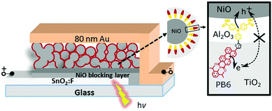
Fig. 1 shows the configuration and working principle of the proposed p-type dye sensitized NiO–dye–TiO2 core–shell solar cells. The donor–π–acceptor dye PB6 was utilized as photosensitizer since its reduction/oxidation potentials in excited state match with the valence band of NiO and conduction band of TiO2.19
The fabrication of the photoelectrode used in this study can be described briefly as follows. A compact NiO layer (60 nm) was sputtered onto a FTO substrate, then a mesoporous NiO layer (1.3 μm) was prepared by doctor-blading NiCl2 gel on FTO glass and sintered at 450 °C for 0.5 h.20 Subsequently, the NiO electrode was immersed into 0.2 mM PB6 dichloromethane (DCM) solution overnight. The dye loading in the film was determined to be 31.6 nmol cm−2 by desorption experiment (see ESI†). After rinsing with methanol, the dye sensitized NiO film was dried and coated with metal oxides by atomic layer deposition (ALD). For NiO–PB6–TiO2 photoelectrode, ca. 10 nm TiO2 layer was coated directly on a dye sensitized NiO film. Because an insulating Al2O3 layer has been proved to be an effective barrier to suppress charge recombination process in DSCs,21–24 an 1 nm inner Al2O3 layer was introduced by ALD on the dye sensitized NiO film, followed by deposition of ca. 10 nm TiO2 coating to form NiO–PB6–Al2O3–TiO2 photoelectrode. In addition, we prepared two reference samples without dye sensitization, denoted NiO–TiO2 and NiO–Al2O3–TiO2, respectively, to exclude the potential photovoltaic performance from the excitation of the p–n junction formed at the interface of NiO and TiO2.
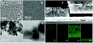
In previous work, we have shown that the TiO2 layer penetrated into the dye sensitized mesoporous NiO electrode. In order to monitor the penetration of Al2O3 into the dye sensitized mesoporous NiO electrode, as well as TiO2 into the Al2O3 coated electrode afterwards, the morphology of NiO–PB6–Al2O3–TiO2 photoelectrode with 1 nm Al2O3 (calculated from the average ALD deposition rate from multi-cycles) was characterized by SEM and TEM (Fig. 2). A more compact surface (Fig. 2b) was observed after subsequent ALD of Al2O3 and TiO2 compared to the mesoporous dye sensitized NiO film (Fig. 2a). From TEM images in Fig. 2c and d, one can note that NiO nanoparticles are coated by a conformal layer, which is assigned to TiO2 and Al2O3 layers. From EDX elements analysis images of the cross section of the electrode, the presence of Al and Ti inside the NiO mesoporous layer was confirmed, signifying that Al2O3 can penetrate into the mesoporous NiO film and that the thin Al2O3 layer does not block the TiO2 penetration.
In order to confirm the potential application of these core–shell photocathodes in solar cells, an 80 nm Au layer was thermally evaporated on the top of these electrodes as back contact to complete the solar cell. The performance of such solar cells was characterized under AM 1.5 G illumination with light intensity of 100 mW cm−2 and the J–V curves are shown in Fig. 3a. A short-circuit current density (Jsc) of 12 μA cm−2 and an open-circuit voltage (Voc) of 0.40 V were obtained in NiO–PB6–TiO2 solar cell. The device based on NiO–TiO2 film without PB6 dye was also fabricated and showed photovoltaic effect, resulting from the p–n junction of NiO–TiO2 due to the direct contact between NiO and TiO2. From Incident Photon-to-Current Efficiency (IPCE) spectra (Fig. 3b), we can note that the PB6 dye in NiO–PB6–TiO2 solar cell has light response in wavelength from 480 nm to 700 nm, which is in agreement with the dye absorption spectrum (Fig. S2, ESI†), proving that the photocurrent is generated by dye. IPCE curve of the NiO–TiO2 solar cell abruptly decreases to zero at wavelengths higher than 500 nm (2.48 eV), and only small part of the visible light can be converted into photocurrent in these solar cells. By using 1 nm Al2O3 to coat NiO, the NiO–TiO2 p–n junction structure in NiO–Al2O3–TiO2 was inhibited and the solar cell did not render any distinguishable photocurrent from J–V and IPCE characterization (see Fig. 3a and b). The same strategy was adopted in a NiO–PB6–Al2O3–TiO2 solar cell, in which Al2O3 could also act as a blocking layer to suppress the charge recombination between injected holes from dye in NiO and injected electrons from dye in TiO2. As the molecular extension of the PB6 dye was estimated to be ca. 2.5 nm, a 1 nm Al2O3 layer should not completely cover the electron donor unit of the PB6 dye, assuming the standing dye configuration on the metal oxide surface. It should provide an opportunity for the TiO2 layer to fully cover the dye acceptor unit and collect the electrons. Noticeably, the photovoltaic performance of the NiO–PB6–Al2O3–TiO2 solar cell was significantly improved compared to the device without Al2O3, showing a Jsc of 23 μA cm−2 and a Voc of 0.48 V, and higher IPCE values in visible region. Meanwhile, a fill factor (FF) of 66% was achieved in the NiO–PB6–Al2O3–TiO2 solar cell, which is the highest FF reported3 in p-type DSCs to our best knowledge (Table S1, ESI†).
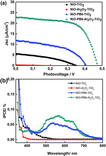 | ||
| Fig. 3 J–V curves and IPCE of different dye sensitized p-type core–shell solar cells and reference solar cells. | ||
To further elucidate the electron and hole injection in NiO–PB6–Al2O3–TiO2 electrode, femtosecond transient absorption spectroscopy was carried out (Fig. S3, ESI†). A pronounced Stark effect was observed upon light excitation, resulting from dye regeneration after hole and electron injection from dye into NiO and TiO2 respectively. The dye regeneration time in NiO–PB6–Al2O3–TiO2 is t1/2 ≤ 500 fs. These are consistent with our previous study of NiO–PB6–TiO2,19 signifying that the Al2O3 layer essentially did not affect the dye regeneration rate. Meanwhile, the same kinetic behaviour as NiO-PB6 reported in our previous study19 was found in NiO–PB6–Al2O3 (Fig. S4, ESI†), further confirming that the Al2O3 layer did not significantly influence hole injection.
In order to gain insight into the effect of the Al2O3 layer on the charge recombination process in solar cells, charge lifetimes as a function of Voc of the solar cells were measured (Fig. 4a). It shows that NiO–PB6–Al2O3–TiO2 solar cell has longer charge lifetime than NiO–PB6–TiO2 solar cell at a given Voc value. From charge extraction experiments (Fig. S5, ESI†), two types of solar cells show almost identical extracted charges at a specific Voc, implying that the Al2O3 layer does not influence the energy band position in either NiO or ALD TiO2. These results suggest that the Al2O3 layer indeed plays the role of an inner barrier layer in suppressing charge recombination between NiO and TiO2, thus contributing to the enhanced Voc and increased Jsc.
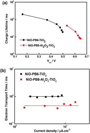 | ||
| Fig. 4 Electron lifetime as a function of Voc and transport time as a function of photocurrent density of NiO–PB6–Al2O3–TiO2 and NiO–PB6–TiO2. | ||
Interestingly, the charge transport time (Fig. 4b) of the NiO–PB6–Al2O3–TiO2 solar cell is shorter than that of the NiO–PB6–TiO2 solar cell. We suggest that the TiO2 formed in the presence of Al2O3 is more compact due to the more hydrophilic properties after ALD Al2O3 (the existence of –OH units on the ALD Al2O3 surface). TiO2 of better quality is expected to be grown on the more hydrophilic surface during ALD in contrast to the NiO surface sensitized with an organic dye,25 although the amorphous structure in both samples is confirmed by TEM. The shorter charge transport time in NiO–PB6–Al2O3–TiO2 solar cell should be responsible for higher Jsc and higher fill factor as compared to the NiO–PB6–TiO2 solar cell. Notably, the charge transport times of both types of solar cells are almost independent of the photocurrent (light intensity), which is unusual for the conventional n-type and p-type DSCs.26,27
One possible explanation is that the TiO2 phase is not continuous inside the mesoporous NiO film (1.3 μm), resulting in that only a very thin NiO film coated by ALD TiO2 works for the charge collection. Another explanation would be that holes and/or electrons transferred via the semiconductor surfaces.28 The former one can also be applied to explain why the photocurrent is much lower than the conventional p-DSCs, although the dye regeneration in the core–shell solar cell is much faster19 and the charge lifetime is comparable to those p-DSCs.26,29 Therefore, making continuous TiO2 layer or increasing the pore-filling of TiO2 inside mesoporous NiO could be a reasonable strategy to significantly improve the efficiency of such solar cells.
As mentioned above, the length of PB6 dye is ca. 2.5 nm, which provides us an opportunity to study the effect of the thickness of Al2O3 on the performance of the solar cells. In principle, a too thin Al2O3 layer cannot effectively suppress charge recombination loss and render unsatisfactory performance. Conversely, a too thick Al2O3 layer could completely bury the dye and the TiO2 cannot sufficiently contact with the acceptor of the dye, which will induce unsatisfactory performance as well due to low regeneration efficiencies. There should be an optimal thickness of Al2O3 giving an optimized performance. Different thicknesses of Al2O3 (0.08, 0.5, 1, 2 and 10 nm) were therefore investigated in NiO–PB6–Al2O3–TiO2 solar cells. From Fig. 5, ca. 1 nm of Al2O3 was proven to be the optimal thickness, because it only covers the entire electron donating unit, triphenylamine (TPA) of PB6, and allows the whole electron acceptor part (perylene monoimide (PMI)) buried inside TiO2, which is expected to be the optimal configuration for charge separation between dye and semiconductors.
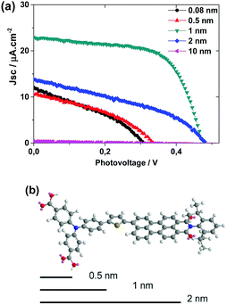 | ||
| Fig. 5 (a) J–V curves for NiO–PB6–Al2O3–TiO2 solar cells with different Al2O3 thickness layers; (b) the 3-D molecular structure of PB6 with 0.5 nm, 1 nm and 2 nm length scales as comparison. | ||
With the Al2O3 layer thinner than 1 nm, less photocurrent and photovoltage was observed, implying more extensive recombination in these devices. With 2 nm Al2O3 film, the photocurrent from the corresponding device also significantly decreased, suggesting that the charge separation probably is inefficient. The hypothesis can be further supported from the results utilizing a 10 nm Al2O3 layer, resulting in solar cells without any obvious photocurrent likely to be caused by the absence of contact between dye and TiO2.
In summary, solid state p-type dye-sensitized NiO–dye–TiO2 core–shell solar cells have been proposed and fabricated for the first time, in which the NiO is sensitized by the organic PB6 dye, after which a TiO2 layer is deposited by ALD to form the dye sensitized NiO–dye–TiO2 core–shell structure. By inserting a thin insulating Al2O3 layer, the charge recombination between NiO and TiO2 after charge injection from dye was significantly retarded. On the basis of the molecular extension of dye, the effect of Al2O3 layer thickness on the solar cell performance was further investigated, showing an optimal thickness of ca. 1 nm for the PB6-based devices. The optimal Al2O3 thickness should be different from different dyes, which encourages us to apply the strategy on other dye systems in future study. Furthermore, other n-type metal oxides can be considered as electron transport materials instead of TiO2 in the core–shell solar cells. This type of solar cell holds the potential to rival conventional liquid p-type dye sensitized solar cells after systematic studies and optimization of different components, and may show potential for application in solar fuel devices as well.
The authors are grateful for the financial support from the Swedish Energy Agency (grant 43599-1). Lei Tian also thanks the China Scholarship Council (CSC) for scholarship support.
Conflicts of interest
The authors declare no competing financial interests.Notes and references
- B. O’regan and M. Grätzel, Nature, 1991, 353, 737 CrossRef.
- J. He, H. Lindström, A. Hagfeldt and S.-E. Lindquist, J. Phys. Chem. B, 1999, 103, 8940 CrossRef CAS.
- V. Nikolaou, A. Charisiadis, G. Charalambidis, A. G. Coutsolelos and F. Odobel, J. Mater. Chem. A, 2017, 5, 21077 CAS.
- A. Nattestad, A. J. Mozer, M. K. Fischer, Y.-B. Cheng, A. Mishra, P. Bäuerle and U. Bach, Nat. Mater., 2010, 9, 31 CrossRef CAS PubMed.
- K. A. Click, B. M. Schockman, J. T. Dilenschneider, W. D. McCulloch, B. R. Garrett, Y. Yu, M. He, A. E. Curtze and Y. Wu, J. Phys. Chem. C, 2017, 121, 8787 CAS.
- E. A. Gibson, A. L. Smeigh, L. Le Pleux, J. Fortage, G. Boschloo, E. Blart, Y. Pellegrin, F. Odobel, A. Hagfeldt and L. Hammarström, Angew. Chem., Int. Ed., 2009, 121, 4466 CrossRef.
- P. B. Pati, L. Zhang, B. Philippe, R. Fernández-Terán, S. Ahmadi, L. Tian, H. Rensmo, L. Hammarström and H. Tian, ChemSusChem, 2017, 10, 2480 CrossRef CAS PubMed.
- F. Li, K. Fan, B. Xu, E. Gabrielsson, Q. Daniel, L. Li and L. Sun, J. Am. Chem. Soc., 2015, 137, 9153 CrossRef CAS PubMed.
- E. A. Gibson, Chem. Soc. Rev., 2017, 46, 6194 RSC.
- L. Zhang, G. Boschloo, L. Hammarström and H. Tian, Phys. Chem. Chem. Phys., 2016, 18, 5080 RSC.
- H. Tian, B. Xu, H. Chen, E. M. Johansson and G. Boschloo, ChemSusChem, 2014, 7, 2150 CrossRef CAS PubMed.
- T. T. T. Pham, S. K. Saha, D. Provost, Y. Farré, M. Raissi, Y. Pellegrin, E. Blart, S. Vedraine, B. Ratier, D. Aldakov, F. Odobel and J. Bouclé, J. Phys. Chem. C, 2017, 121, 129 CAS.
- N. J. Cherepy, G. P. Smestad, M. Grätzel and J. Z. Zhang, J. Phys. Chem. B, 1997, 101, 9342 CrossRef CAS.
- Y. Tachibana, J. E. Moser, M. Grätzel, D. R. Klug and J. R. Durrant, J. Phys. Chem., 1996, 100, 20056 CrossRef CAS.
- F. Cao, G. Oskam, G. J. Meyer and P. C. Searson, J. Phys. Chem., 1996, 100, 17021 CrossRef CAS.
- Y.-M. Lee, C.-H. Hsu and H.-W. Chen, Appl. Surf. Sci., 2009, 255, 4658 CrossRef CAS.
- Y.-M. Lee and C.-H. Lai, Solid-State Electron., 2009, 53, 1116 CrossRef CAS.
- K. H. Wong, K. Ananthanarayanan, S. R. Gajjela and P. Balaya, Mater. Chem. Phys., 2011, 125, 553 CrossRef CAS.
- L. Tian, J. Föhlinger, P. B. Pati, Z. Zhang, J. Lin, W. Yang, M. Johansson, T. Kubart, J. Sun, G. Boschloo, L. Hammarström and H. Tian, Phys. Chem. Chem. Phys., 2018, 20, 36 RSC.
- L. D’Amario, L. J. Antila, B. Pettersson Rimgard, G. Boschloo and L. Hammarström, J. Phys. Chem. Lett., 2015, 6, 779 CrossRef PubMed.
- Z. Bian, T. Tachikawa, S.-C. Cui, M. Fujitsuka and T. Majima, Chem. Sci., 2012, 3, 370 RSC.
- R. J. Lindquist, B. T. Phelan, A. Reynal, E. A. Margulies, L. E. Shoer, J. R. Durrant and M. R. Wasielewski, J. Mater. Chem. A, 2016, 4, 2880 CAS.
- C. Prasittichai and J. T. Hupp, J. Phys. Chem. Lett., 2010, 1, 1611 CrossRef CAS.
- G. Natu, Z. Huang, Z. Ji and Y. Wu, Langmuir, 2011, 28, 950 CrossRef PubMed.
- N. P. Kobayashi, C. L. Donley, S.-Y. Wang and R. S. Williams, J. Cryst. Growth, 2007, 299, 218 CrossRef CAS.
- H. Tian, J. Oscarsson, E. Gabrielsson, S. K. Eriksson, R. Lindblad, B. Xu, Y. Hao, G. Boschloo, E. M. Johansson and J. M. Gardner, Sci. Rep., 2014, 4, 4282 CrossRef PubMed.
- M. Quintana, T. Edvinsson, A. Hagfeldt and G. Boschloo, J. Phys. Chem. C, 2007, 111, 1035 CAS.
- H. Zhu, A. Hagfeldt and G. Boschloo, J. Phys. Chem. C, 2007, 111, 17455 CAS.
- L. Li, E. A. Gibson, P. Qin, G. Boschloo, M. Gorlov, A. Hagfeldt and L. Sun, Adv. Mater., 2010, 22, 1759 CrossRef CAS PubMed.
Footnote |
| † Electronic supplementary information (ESI) available. See DOI: 10.1039/c8cc00505b |
| This journal is © The Royal Society of Chemistry 2018 |

