
 Open Access Article
 This Open Access Article is licensed under a
 Creative Commons Attribution 3.0 Unported Licence
Perspective on carbazole-based organic compounds as emitters and hosts in TADF applications
Brigitte
Wex
 a and
Bilal R.
Kaafarani
*b
a and
Bilal R.
Kaafarani
*b
aDepartment of Natural Sciences, Lebanese American University, Byblos, Lebanon
bDepartment of Chemistry, American University of Beirut, Beirut 1107-2020, Lebanon. E-mail: bilal.kaafarani@aub.edu.lb
First published on 11th July 2017
Abstract
The field of organic light-emitting devices (OLEDs) has undergone a remarkable journey since its discovery by Tang and VanSlyke with an alternation of utilizing fluorescence and phosphorescence as the emitting vehicle. The latest generation of thermally activated delayed fluorescence (TADF) materials harvest triplet excited states back into the singlet manifold. This booming field has yielded a large array of new compounds as both emitters and hosts. This review is limited to TADF emitters utilizing at least one carbazole unit as a donor and organized according to the various acceptor building blocks such as cyanophenyl, pyridine, biphenyls, anthraquinone, phenyl(pyridine-2-yl)methanone, benzophenone, xanthon, sulfones, triazines, benzils, dicyanopyrazines, diazatriphenylene, and others. A survey of carbazole-containing host materials follows. Density functional theory (DFT) has carved out a significant role in allowing the theoretical prediction of ground state properties for materials applied in OLED technology. Time-dependent DFT extends the reach to model excited state properties important to rationalize the light-output in OLED technology. For TADF, two fundamental factors are of interest: significant separation of frontier molecular orbitals and minimal singlet–triplet energy gap (ΔEST). In this review, the utilization of DFT calculations to optimize geometries for the visualization of frontier molecular orbital separation was surveyed to find that the B3LYP/6-31G(d) level of theory is the overwhelmingly used approach. In addition, we review the more in-depth approaches to utilizing DFT and time-dependent DFT (TD-DFT) with optimized percentage Hartree–Fock (OHF) and long-range corrected hybrid functionals, tuning procedures and others in an attempt to best quantify the size of ΔEST as well as the nature of the triplet state as locally excited state (LE) and charge-transfer state (CT).
 Brigitte Wex | Brigitte Wex is an Organic and Computational Chemist. She received her MSc in Molecular Biology in 2001 and a PhD in Photochemical Sciences from Bowling Green State University in 2005. After Postdoctoral work at the Flexible Display Center at the School of Engineering at Arizona State University in 2006, she joined the Department of Natural Sciences at the Lebanese American University (LAU) in Byblos, Lebanon as an Assistant Professor. She is currently an Associate Professor working on the synthesis and computational assessment of materials for optoelectronic device applications. |
 Bilal R. Kaafarani | Bilal R. Kaafarani is an Organic and Materials Chemist. He received his PhD in Photochemical Sciences from Bowling Green State University in 2002. After Postdoctoral work at the University of Arizona and the Georgia Institute of Technology, he joined the Department of Chemistry at the American University of Beirut (AUB) as Assistant Professor of Chemistry in September 2004. He was promoted to Associate Professor in 2010 and subsequently to Full Professor in 2016. Kaafarani’s research area spans the field of organic electronics and sensors. Kaafarani is an advocate of interactive learning, experiential learning and transformative education. He is the founder of the Organic Competition (www.aub.edu.lb/oc) and the Medical Research Volunteer Program (www.aub.edu.lb/mrvp) at AUB. |
OLEDs – an introduction
In an organic light-emitting device (OLED), light is generated by recombination of electrically generated, bound electron–hole pairs, called excitons. Excitons are generally formed via one of two operating mechanisms, direct charge carrier recombination of injected charge carriers (electrons from the cathode and holes from the anode) or host-to-dopant energy transfer under the application of an energy transfer mechanism (Förster or Dexter). Spin statistics thereby predicts exciton formation as 25% of the time as singlet and 75% of the time as triplet.1 Singlet excitons produce electroluminescence by a fast process called fluorescence. Triplet excitons produce electroluminescence by a slow process called phosphorescence. Emission is thereby governed by selection rules known as El-Sayed rules.2 Specifically in the case of purely organic materials, slow radiative decay rates are observed, which effectively compete only at very low temperature, generally 77 K. At this temperature, competing non-radiative decay processes are slowed down and phosphorescence is observed. Thus, at ambient temperature, these triplet excitons are generally lost by non-radiative decay processes.The development of OLED technology has gained tremendous strides. The first generation devices were based on harvesting the emission generated from singlet excitons.3 Hence, the first generation OLED devices were inherently limited to an internal maximum quantum efficiency of 25% since triplet excitons were lost predominantly by non-radiative transitions as outlined above.4 The maximum theoretical external quantum efficiency is <5% in fluorescent OLEDs, which can be calculated using eqn (1).5,6
| ηext = ηintηout = γηSTΦPLηout | (1) |
The second generation OLED devices were the result of a major breakthrough in improving the external quantum efficiency, achieved through the introduction of transition metal complexes. Therein, phosphorescence-based OLEDs named PHOLEDs based on organometallic phosphors containing noble metals were utilized to harvest the 75% triplet excitons. These PHOLED devices achieved close to 100% internal quantum efficiency due to singlet–triplet mixing through effective spin–orbit coupling.7,8 However, transition metal complexes9 based on metals such as iridium,10 platinum,11–13 osmium,14 europium,15 and ruthenium16 are costly and scarce resources of low abundance, and are as such not sustainable for mass consumer goods applications. In addition, upon disposal, these materials are potentially harmful for the environment.17 Significant drawbacks were observed for PHOLEDs due to exciton annihilation among the long-lived triplet states (μs to ms), weakness of the chemical bonds to the metals leading to decomposition, and limited molecular design opportunity due to the restriction set forth by the nature of the geometry of the transition metal complexes.
Both, triplet–triplet annihilation (TTA) and thermally activated delayed fluorescence (TADF) allow dark triplet states to be harnessed by repopulating singlet excitons.18 TTA is also called P-type delayed fluorescence as it was first observed in pyrene. TADF is also called E-type delayed fluorescence as it was first observed in eosin. The application of TTA for OLEDs allowed the theoretical limit of 25% to be exceeded; however, an inherent limitation for the formation of radiative excitons was shown to be (25% + 75% × 0.5) = 62.5%.19 The third generation of OLED technology arose from TADF. In TADF materials, the absorption of environmental thermal energy leads to augmentation of the population of the electro-generated emissive singlet excitons from electro-generated, non-radiative triplet excitons5,20 by a process called reverse intersystem crossing (RISC) followed by emission. This ensuing light emission is thus, by majority, delayed fluorescence.21 RISC occurs effectively if the singlet–triplet energy gap (ΔEST) is small, eqn (2).22
ΦRISC ∝ kRISC = kRISC′![[thin space (1/6-em)]](https://www.rsc.org/images/entities/char_2009.gif) exp[−ΔEST/(kBT)] exp[−ΔEST/(kBT)] | (2) |
Notably, triplet to singlet transitions are forbidden when considering the zero order approximation. TADF herein takes advantage of first order mixing that includes spin–orbit and electron spin interactions. The spin–orbit coefficient λ relates spin orbit interaction (HSO) to ΔEST as described by eqn (3).23 Spin orbit coupling thereby means an electromagnetic interaction between the electron’s spin and the magnetic field created by the electron orbiting around the nucleus, the small ΔEST maximizes spin–orbit coupling and thus favors the transition.
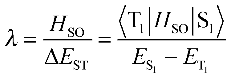 | (3) |
 for S1 is proportional to the orbital overlap integral
  and the orbital overlap integral is related to the spatial overlap of orbitals.25
Materials with TADF behavior are designed under application of several design principles. The design principles for TADF materials include the separation of relevant transition orbitals in order to minimize ΔEST18 as outlined above. Often this statement is reduced to the separation of the highest occupied molecular orbital (HOMO) and the lowest unoccupied molecular orbital (LUMO). This, of course, implies the assumption that S1 is a HOMO–LUMO transition, which, depending on the structure, is not necessarily the case. A separation of overlap to minimize ΔEST can be achieved through a twisted intermolecular charge transfer (TICT)26,27 framework, which allows only a small relaxation energy due to steric hindrance between donor and acceptor moieties and localization of the triplet exciton or the enlargement of the distance separating electrons (r1 − r2) of the columbic interaction operator.28 Donor–acceptor (D–A) compounds trigger intermolecular charge transfer (ICT) states, whereby an employed change in solvent polarity modulates the emission properties by specifically stabilizing the charge-transfer (CT) state over the locally excited (LE) state according to eqn (4).29
| ΨICT = c1|D*A〉Loc + c2|DA*〉Loc + c3|D+A−〉CT | (4) |
Moving to the device preparation point of view, the process of determining ΔEST from solution data by the energy differences of the singlet excited state derived from room temperature fluorescence spectra and triplet excited state from low temperature phosphorescence leads to a significantly different value for ΔEST in comparison to the data obtained in a host film at room temperature after extracting the barrier to RISC as shown by Lee et al.30a and Santos et al.30b These ΔEST differences are particularly important to consider, when choosing experimental data for benchmark studies using computational approaches.
With enough thermal energy present in the system, the thermally activated RISC pathway leads to internal quantum efficiencies (IQEs) of unity considering the singlet state.
The design principle also needs to include the consideration that at the same time, the S1 state needs to remain radiative. The radiative decay rate (kr) constant is dependent on oscillator strength, i.e. overlap integral. Thus, a minimal orbital overlap21 needs to be maintained between the relevant orbital energy levels to ensure that the high kr of the radiative decay rates is >106 s−1.21
Highly efficient electroluminescence from TADF emitters is ensured by dispersing TADF emitters at a low concentration into a suitable host matrix in an effort to minimize concentration quenching and TTA.20,31 The role of the host matrix is highlighted in detail below.
Both TADF and PHOLEDs can achieve 100% internal quantum efficiency; these devices utilize singlet and triplet excitons as the emitting state, respectively. The external quantum efficiency (EQE) has reached up to 25% for blue, red and green devices in PHOLEDs, while the EQE in TADF lags slightly behind, particularly for blue TADF devices.32 Organic synthesis of molecules towards TADF applications is rich in material diversity. The emitting species in TADF are lower in energy (singlet, triplet) when comparing the emission wavelength of both types of devices. Thus, the driving voltage in TADF devices may be lower since a narrower bandgap host material may be used.33
Similar to PHOLEDs, blue TADF-based OLED devices exhibit efficiency roll-off at high current density. Roll-off behavior is characterized by a decrease of device efficiency when high luminance is attempted under high current conditions.34,35 PHOLEDs exhibit roll-off behavior attributed to long triplet lifetimes (τT) and large ΔEST. Thus, shortening the excited state lifetime (τTADF) may suppress TTA, singlet–triplet annihilation (STA) or triplet polaron exciton annihilation36 and minimize ΔEST and thereby may lead to TADF devices with minimal efficiency roll-off.35,37,38
A large range of building blocks have been used as a foundation for TADF materials including acridines,39–41 phenoxazines,42 spirobased hydrocarbons,43–45 pyridines,46 anthraquinones,47 oxadiazoles,48–50 phosphine oxides,51–53 dihydrophenazines,31 heptaazaphenalenes,54 triazines,55,56 dicyanobenzenes (phthalonitriles),21 diphenylsulfones,57 arylketones such as xanthone,30 benzophenones,58 thioxanthones,59 heptazines,60 and cuprous complexes in their specific role as donor and acceptor moieties.61,62 However, acridines and diphenylsulfones were shown to be chemically unstable under device conditions.63 A series of reviews on TADF materials and devices have been published in foreign languages.64–71 Adachi’s most recent review written in Japanese on the third generation organic electroluminescence was translated into English;3 the review by Tao et al. traces a timeline of development in the field of TADF materials across a wide range of classes of materials.72 The review of Bergmann et al.73 specifically compares organic and metal–organic TADF materials. Therein, an overview of the origin of the TADF phenomenon is given, the chronologic appearance of materials for TADF as well as the status quo. Leitl et al. specifically reviewed Cu(I) complexes as applied in TADF applications.74 In parallel with our work on this review, Wong and Zysman-Colman75 published a seminal review on purely organic TADF materials for OLEDs. Herein, we focus solely on carbazole-containing materials for TADF applications. We trace the development of understanding the TADF process along this journey as emitters and hosts in oligomers, dendrimers and others. A short survey of computational approaches to assess molecules in TADF applications and further their understanding is presented.
Carbazole
Carbazole has been widely used toward optoelectronic device applications in general as a source for host materials and emitters in the form of oligomers, dendrimers and polymers.76–79 Carbazole is an excellent hole-transporter.20 The advantages of carbazole as an organic material are highlighted in four fundamental advantages, (1) inexpensive starting material; (2) ease of functionalization at the nitrogen atom and thus property modification without altering the backbone; (3) several linkage positions on the carbazole backbone; (4) aromatic properties that confer stability under a wide range of conditions.78 Before the application of carbazole in TADF is explored, some fundamental spectroscopic and electrochemical properties of carbazole are reviewed.1878 marks the first reference to carbazole in the scientific literature.80 Carbazole was then extracted from the anthracene fraction of coal tar. In the ground state, carbazole shows hydrogen bonded complexes. Solvents containing OH groups, form complexes with carbazole of NH⋯O type in preference over OH⋯π type, as well as a bend in the molecular geometry. The dipole moment of carbazole changes from 2 D in the ground state to 3.1 D in the first excited state.81 The absorption spectrum of carbazole in methanol is characterized by three weak absorption bands at 335 nm, 323 nm and 294 nm with extinction coefficients around 103 M−1 cm−1 and an additional three absorption bands at 252 nm, 244 nm and 233 nm with a 10 fold higher extinction coefficient of 104 M−1 cm−1.82 The absorption spectrum in a single-crystal matrix of fluorene at very low temperature (15 K) yields absorption bands at 330 nm, 290 nm, 255 nm, and 230 nm. The absorption as well as the high fluorescence emission properties of carbazole appear to be similar in nature to π → π* transitions due to the fact that the non-bonding electron pair of the singly bonded nitrogen is perpendicular to the ring plane, thus allowing the effective overlap with the π orbitals of the neighboring carbons.18 Carbazole shows the two first absorption bands with low lying states of 1A1 and 1B1 symmetry,81 wherein 1A1 is of lower energy level.83 No significant change in the equilibrium nuclear configuration is observed giving rise to the absence of significant progression in the vibrational mode. A linear relationship and rise in intensity between the 1Lb band and the polarity of the solvent is observed.84 Replacing the N–H hydrogen with alkyl groups significantly only effects the absorption wavelength of the 1Lb band.84
Studies involving the photoselection technique indicate that the lowest lying absorption band and fluorescence band exhibit significant mixed polarization hinting toward a forbidden character for both.85 A mirror image symmetry is observed for the absorption and fluorescence emission bands of carbazole. The fluorescence quantum efficiency of carbazole is reported at 0.38.86,87 The fluorescence lifetime of carbazole is 15 ns at 77 K in polar EPA (diethyl ether, isopentane and ethanol (5:5:2)) solvent.85 Carbazole has a high ET of 3.02 eV88 and the lowest energy triplet state is assigned to 3La.85 A phosphorescence lifetime of 7.7 s was determined at 77 K in polar EPA.85 Hereby, the phosphorescence is influenced by the direct spin–orbit coupling mechanism to the 1B2 ground state.89 It is worth noting that the triplet energy of carbazole is higher in comparison to related biphenyl compounds such as fluorene and biphenyl with 2.90 eV and 2.94 eV, respectively.90
The electrochemical behavior of carbazole was thoroughly reviewed by Karon and Lapkowski.91 Nascent carbazole exhibits one-electron oxidation with a potential of 1.2 eV vs. SCE. The oxidation leads to dicarbazyls and is sensitive to pH. The cation is unstable unless the nitrogen as well as positions 3 and 6 of the ring system are blocked.92
For all of the following materials shown as structures in Fig. 1–12, the material’s data in terms of photophysical, electrochemical, and device performance are summarized in Tables 1–3. The absence of standardized reporting of device characteristics along with a variety of approaches to determine and report HOMO/LUMO data is noted. The US Department of Energy provides the OLED Testing Program93 geared towards the OLED community to accelerate research in this field. Initiatives such as this may serve as an incubator to develop guidelines for reporting to allow cross comparison. Whenever experimental data were only presented in figures, no value was entered in the tables. Quantum yields of TADF materials in thin films were reported unless the data was acquired in NPD or other host materials.
 | ||
| Fig. 1 Structures of carbazolyl cyanobenzene derivatives, tetra and pentacabazoylpyridine and benzenes, and carbazoylated biphenyls. | ||
 | ||
| Fig. 2 TADF-materials based on anthraquinone, phenyl(pyridin-2-yl)methanone, benzophenone, and xanthone. | ||
 | ||
| Fig. 3 Sulfoxide-containing TADF materials and others. | ||
 | ||
| Fig. 4 Carbazoles and fused carbazoles on triazine acceptors. | ||
 | ||
| Fig. 5 Twin-emitting cores based on carbazoles; carbazoles on diverse cores, and carbazoles linked to benzil and dicyanopyrazine and 1,4-diazatriphenylene. | ||
 | ||
| Fig. 6 Boron-, carborane- and palladium-containing TADF emitters. | ||
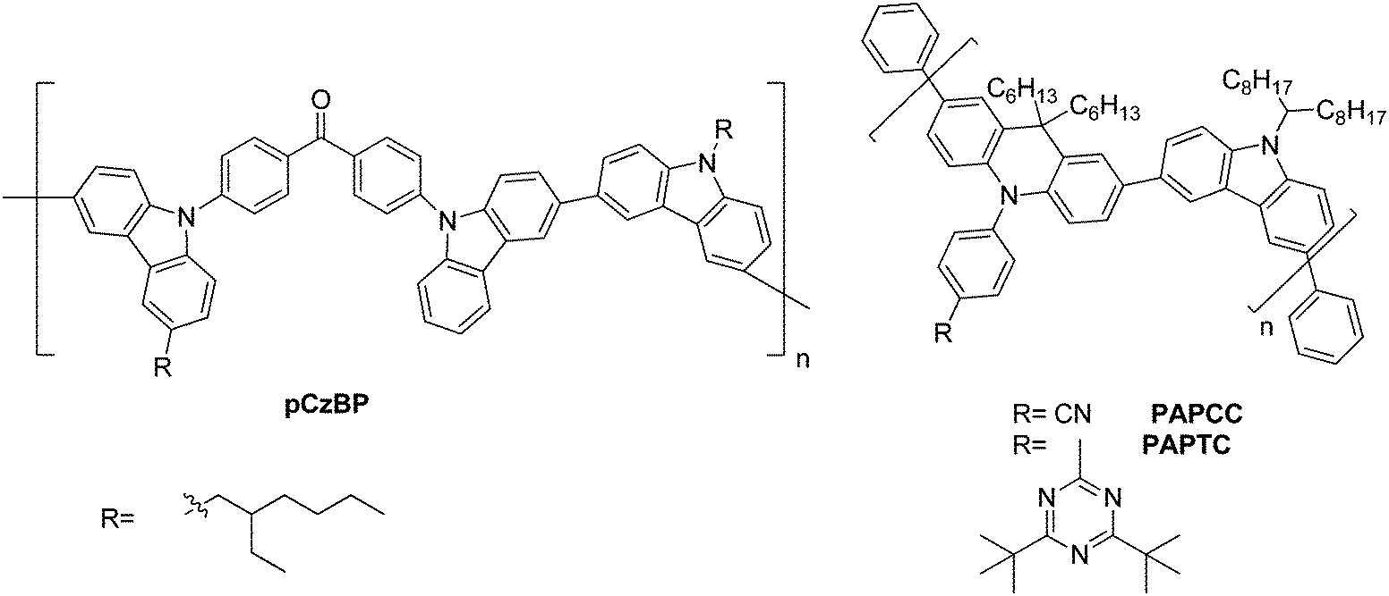 | ||
| Fig. 7 Carbazole-based polymeric TADF materials pCzBP, PAPCC, and PAPTC. | ||
 | ||
| Fig. 8 Benzophenone- and sulfonate-based dendrimers. | ||
 | ||
| Fig. 9 Self-hosting, solution-processable dendrimeric TADF materials and dendrimers with triazine-cores. | ||
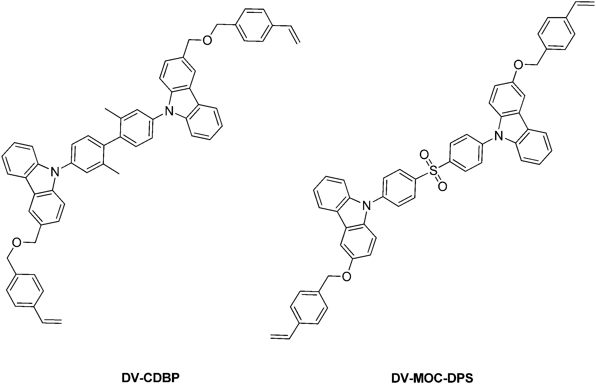 | ||
| Fig. 10 Cross-linkable host (DV-CDBP) and emitter (DV-MOC-DPS) precursors for TADF applications. | ||
 | ||
| Fig. 11 Small molecule and dendrimeric host materials for TADF applications. | ||
 | ||
| Fig. 12 Carbazole-based host materials containing sulfur, ternary and quaternary phosphine oxide, and fluorenes. | ||
| Ref. | Compound | Device geometry | Turn-on (V) | L (cd m−2, V) | CE (cd A−1) | PE (lm W−1) | EQE (%) | CIE (x, y) | HOMO (eV) | LUMO (eV) | ΔEgap (eV) | Abs (nm) | PL nm (QY) | PL (TF) | E S1 (eV) | E T1 (eV) | ΔES–T (eV) |
|---|---|---|---|---|---|---|---|---|---|---|---|---|---|---|---|---|---|
| L: luminance; CE: current efficiency; PE: power efficiency; EQE: external quantum efficiency; α-NPD: 4,4-bis[N-(1-naphthyl)-N-phenylamino]-bipheny; mCP: 1,3-bis(N-carbazolyl)benzene; PPT: 2,8-bis(diphenylphosphoryl)dibenzo[b,d]thiophene; TPBi: 1,3,5-tris(N-phenylbenzimidazole-2-yl)benzene; TSPO1: diphenylphosphine oxide-4-(triphenylsilyl)phenyl; PPF: 2,8-bis(diphenylphosphoryl)dibenzo[b,d]furan; HAT-CN: 2,3,6,7,10,11-hexacyano-1,4,5,8,9,12-hexaazatriphenylene; CCP: 9-phenyl-3,9-bicarbazole; TmPyPb: 3,3′-[5′-[3-(3-pyridinyl)-phenyl] [1,1′:3′,1-terphenyl]-3,3-diyl]bis-pyridine; HATCN: dipyrazino[2,3-f:2′,3′-h]quinoxaline-2,3,6,7,10,11-hexacarbonitrile; NPB: N,N′-bis(naphthalene-1-yl)-N,N′-bis(phenyl)-benzidine; T2T: 2,4,6-tris(biphenyl-3-yl)-1,3,5-triazine; TCTA: 4,4′,4′′-tris(N-carbazolyl)triphenylamine; DpyPA:Liq: 9,10-bis(3-(pyridin-3-yl)phenyl)anthracene:(8-hydroxyquinolinolato)-lithium; PVK: poly(9-vinylcarbazole); SiCz: diphenyldi(4-(9-carbazolyl)phenyl)silane; TPAC: 1,1-bis(4-di-p-tolylaminophenyl)-cyclohexane; 4CzPy: 2,3,5,6-tetracarbazole-pyridine; TAPC: 4,4′-cyclohexylidene-bis[N,N-bis(4-methylphenyl)aniline]; DPEPO: bis[2-(diphenylphosphino)phenyl] ether oxide; Tris-PCz: 9,9′-diphenyl-6-(9-phenyl-9H-carbazol-3-yl)-9H,9′H-3,3′-bicarbazole; Bpy-TP2: 2,7-bis(2,2′-bipyridin-5-yl)-triphenylene; TPAP: triphenylamine-containing polymer; PPBI: 4-isopropyl-4′-methyldiphenyl-iodonium tetrakis(pentafluorophenyl)borate; 3TPYMB: tris-[3-(3-pyridyl)mesityl]borane. LE: locally excited state; ICT: intermolecular charge transfer state; hex: hexane; tol: toluene.a Photoelectron spectroscopy.b HOMO-absorption edge.c Measured in toluene.d Maximum value.e CV experiment.f Measured in THF.g N2 atmosphere.h Measured in thin film.i First phosphorescence peak zero–zero energy (E0–0) measured at low temperature.j Measured in DCM.k Maximum value.l Estimated from UV-vis absorption edge.m Zero–zero energy (E0–0) of the fluorescence spectrum at room temperature.n 1% in PS film.o Measured at low temperature.p Measured in CHCl3.q Calculated from onset of fluorescence.r Calculated from onset of phosphorescence.s HOMO − Eg.t Calculated from onset voltages of redox peaks.u Photoelectron yield spectroscopy of thin film.v DPEPO film (10 wt%).w 1240/λonset.x Measured in 2-MeTHF.y Low current density.z Calculated by TD-DFT at the B3LYP/6-31G(d) level of theory.aa Solution, 3.16 V for film.bb FWHM 55 nm.cc Value recorded at 100 cd m−2.dd Measured in cyclohexane.ee Ar atmosphere.ff Value recorded at 1 cd m−2; oxygen-free solution.gg Shoulder.hh THF/water mixture.ii Neat film deposited on a quartz substrate.jj Calculated by TD-DFT at the PBE1PBE/6-31G(d) level.kk Oxidation and reduction potentials noted in ESI.ll Measured at room temperature; mm Es–ET as determined from the Arrhenius plot of rate constant for RISC.mm LUMO = HOMO + Eg (optical energy gap). | |||||||||||||||||
| Masui et al.95 | 2CzPN | ITO (100 nm)/α-NPD (35 nm)/mCP (10 nm)/mCP:60 wt% 2CzPN (15 nm)/PPT (10 nm)/TPBi (40 nm)/LiF (0.8 nm)/Al (100 nm) | 7.4 | — | — | — | 13.6 | 0.17, 0.30 | −5.8a | −3.0b | 2.8 | — | — | — | — | — | 0.09 |
| Cho et al.117 | DCzIPN | ITO (150 nm), PEDOT:PSS (60 nm)/TAPC (20 nm)/mCP (10 nm)/mCP:DCzIPN/TSPO1 (35 nm)/LiF (1 nm)/Al (200 nm) | 3.5 | — | — | — | 16.4d | 0.17, 0.19 | −6.26e | −3.56e | 2.8 | — | 447, 455 (0.35)c | — | 2.77 | 2.72f | 0.05 |
| Lee et al.32 | BFCz-2CN | ITO (50 nm)/PEDOT:PSS (60 nm)/TAPC (20 nm)/mCP (10 nm)/mCP:BFCz-2CN or BTCz-2CN (25 nm, 1%)/TSPO1 (35 nm)/LiF (1 nm)/Al (200 nm) | 4.0 | — | — | 12.1d | — | — | −6.19e | −3.58e | — | 310, 310–430 | (0.946)g | — | 2.59h | 2.46i | 0.13 |
| BTCz-2CN | 4.0 | — | — | 11.8d | — | — | −6.17e | −3.58e | — | (0.94)g | — | 2.63h | 0.17 | ||||
| Mei et al.110 | 4CzCF3Ph | ITO/PEDOT:PSS (40 nm)/mCP:4CzCF3Ph (10 wt%, 40 nm)/TmPyPB (60 nm)/LiF (0.8 nm)/Al (100 nm) | 4.8 | 1032d | 1.03 | — | 0.7 | 0.17, 0.18 | −5.6e | −2.62e | 2.98 | 288, 321, 332j | 440j | 445 | 3.02 | 2.78 | 0.24 |
| Zhang et al.111 | 4CzBN | ITO/HATCN (5 nm)/NPB (30 nm)/TCTA (10 nm)/mCBP:4CzBN or 4TCzBN (40 wt%) (30 nm)/DpyPA:Liq (1:1, 30 nm)/LiF (0.5 nm)/Al (150 nm) |
3.3 | — | — | 15.7d | 10.6d | 0.17, 0.20 | −5.73e | −2.87e | — | 420c | 442c | (0.49g) | 3.00 | 2.70 | 0.30 |
| 4TCzBN | 3.3 | — | — | 24.4d | 16.2d | 0.16, 0.22 | −5.48e | −2.73e | — | 420c | 456c | (0.68g) | 2.86 | 2.62 | 0.24 | ||
| Cho et al.101 | m4CzIPN | ITO (120 nm)/PEDOT:PSS (60 nm)/PVK (15 nm)/SiCz:m4CzIPN (25 nm, 1 wt%)/TSPO1 (5 nm)/TPBI (30 nm)/LiF (1 nm)/Al (solution processed) | — | — | — | 13.2d | 8.2d | 0.29, 0.57 | — | — | — | — | (0.67)g | — | — | — | — |
| Cho et al.142 | 4CzIPN | ITO/PEDOT:PSS (60 nm)/TAPC (20 nm)/ mCP (10 nm)/4CzIPN:4CzTPN-Ph (25 nm)/ TmPyPB (30 nm)/LiF (1 nm)/Al (100 nm) | 3.0 | — | 15.8 | — | 0.1 | 0.49, 0.49 | −5.2e | −3.1e | — | — | — | — | — | — | |
| Uoyama et al.21 | 4CzIPN | ITO/α-NPD (35 nm), 4CzIPN or CzTPN-Ph:CBP (5 wt%, 15 nm)/TPBi (65 nm)/LiF (0.8 nm)/Al (70 nm) | — | — | — | — | 19.3 | — | — | — | — | — | 507 (93.8)g | — | — | — | — |
| 4CzTPN-Ph | — | — | — | — | 11.2 | — | — | — | — | — | 577 (26.3)g | — | — | — | — | ||
| 4CzTPN-Me | — | — | — | — | — | — | — | — | — | — | — | 561 (47.4)g | — | — | — | — | |
| 4CzTPN | — | — | — | — | — | — | — | — | — | — | — | 535 (71.6)g | — | — | — | — | |
| 4CzPN | — | — | — | — | — | — | — | — | — | — | — | 525 (74.4)g | — | — | — | — | |
| Zhang, et al.113 | CyFbCz | ITO/NPB (40 nm)/TCTA (10 nm)/8 wt% CyFbCz:mCP (25 nm)/TPBi (35 nm)/LiF (1 nm)/Al (100 nm) | 4.1 | 2526.8k | 6.64k | 2.66k | — | 0.18, 0.13 | −5.3e | −2.4b | 2.94l | 384, 364, 336, 323c | 426c | 437 | 2.89m | 2.8i | 0.09 |
| Mei et al.110 | 5CzCF3Ph | ITO/PEDOT:PSS (40 nm)/mCP:5CzCF3Ph (10 wt%, 40 nm)/TmPyPb (60 nm)/LiF (0.8 nm)/Al (100 nm) | 3.9 | 2436 | 11.8 | — | 5.2 | 0.21, 0.33 | −5.57e | −2.75e | 2.82 | 290, 319, 330j | 481j | 495 | 2.82 | 2.80 | 0.02 |
| Cho et al.101 | t4CzIPN | (ITO) (120 nm)/PEDOT:PSS (60 nm)/PVK (15 nm)/SiCz:t4CzIPN (25 nm, 1 wt%)/TSPO1 (5 nm)/TPBI (30 nm)/LiF (1 nm)/Al (solution processed) | — | — | — | 42.7d | 18.3d | 0.31, 0.59 | — | — | — | — | (0.78)c,g | — | — | 2.39f,i | — |
| Cho et al.114 | 5CzCN | ITO/PEDOT:PSS (60 nm)/PVK (15 nm)/SiCz:5CzCN (25 nm, 15%)/TSPO1 (5 nm)/TPBI (30 nm)/LiF (1 nm)/Al (200 nm) solution processed | — | — | — | 43.4d | 18.7d | 0.17, 0.27 | −6.29e | −3.44e | — | — | (0.71)g | — | 2.95n,o | 2.79n,o | 0.19 |
| Zhang et al.111 | 5CzBN same as 5CzCN | ITO/HATCN (5 nm)/NPB (30 nm)/TCTA (10 nm)/mCBP:5CzBN or 5TCzBN (40 wt%) (30 nm)/DpyPA:Liq (1:1, 30 nm)/LiF (0.5 nm)/Al (150 nm) |
3.0 | — | — | 40.0d | 16.7d | 0.22, 0.40 | −5.55e | −2.74e | — | 420c | 464c | (0.70g) | 2.90 | 2.68 | 0.22 |
| 5TCzBN | 2.9 | — | — | 56.1d | 21.2d | 0.21, 0.41 | −5.45e | −2.74e | — | 420c | 480c | (0.86g) | 2.77 | 2.60 | 0.17 | ||
| Tang et al.112 | 4CzCNPy | ITO/PEDOT:PSS (40 nm)/mCP:4CzCNPy (8 wt%, 30 nm)/TmPyPB (60 nm)/LiF (0.8 nm)/Al (100 nm) | 4.7 | 16305d |
35.4d | 17.9d | 10.4d | 0.35, 0.59 | −5.72e | −3.26b | — | 285, 336, 456p | 536p (0.549)c,g | 560 | 2.28m | 2.21i | 0.07 |
| Cho et al.116 | CNBPCz | PEDOT:PSS (60 nm)/TAPC (20 nm)/mCP (10 nm)/DPEPO:CNBPCz or DPEPO:CzBPCN 5% (25 nm)/TSPO1 (5 nm)/TPBI (30 nm)/cathode | — | — | — | — | 4.8 | — | — | — | — | — | 458 (0.46)c,g | — | 3.10 | 2.83 | 0.27 |
| CzBPCN | — | — | — | — | 14.0 | 0.14, 0.12 | — | — | — | — | 453 (0.76)c,g | — | 3.14 | 2.87 | 0.27 | ||
| Cho et al.117 | DDCzIPN | ITO/PEDOT:PSS/TAPC/mCP/mCP:BmPyPb:DDCzIPN/TSPO1/Li/Al | 3.5 | — | — | 21.5 | 18.9d | 0.22, 0.46 | −6.4e | −3.88e | — | 230, 287, 329, 400f | (0.91)c | — | 2.6m,n | 2.47f,i,n | 0.13 |
| Zhang et al.47 | AQ-DTBu-Cz | ITO/HATCN (10 nm)/Tris-PCz (30 nm)/10 wt% TADF:CBP (30 nm)/T2T (10 nm)/Bpy-TP2 (40 nm)/LiF (0.8 nm)/Al | 3.0 | — | — | — | 9d | — | — | — | — | — | (0.58)c | — | — | — | 0.22 |
| Rajamalli et al.119 | mDCBP | ITO/NPB (40 nm)/mCP (10 nm)/DPEPO:mDCBP (30 wt%) (30 nm)/PPT (5 nm)/TmPyPb (60 nm)/LiF (1 nm)/Al (100 nm) | 2.8 | 8900 @ 18.0 V | 42.8 @ 3.5 V | 38.2 @ 3.5 V | 14.7 @ 3.5 V | 0.22, 0.44 @ 8 V | −5.72e | −2.72b | 3.0q | 334, 372c | 467c | — | — | 2.94r | 0.15 |
| Rajamalli et al.120 | BPy-pC | ITO/NPB (30 nm)/TAPC (20 nm)/mCBP/dopant [7 wt%] (30 nm)/PPT (10 nm)/TmPyPb (60 nm)/LiF (1 nm)/Al (100 nm) | — | 2183 @ 13 V | 5.0 @ 4.0 V | 3.9 @ 4.0 V | 4.2 (4.0) | 0.16, 0.13 @ 8 V | −5.68e | −2.54b | 3.14q | 290, 338, 359c | 440 (0.012)c | (0.38) | 3.14 | 2.85 | 0.29 |
| BPy-pTC | Same device geometry as above | — | 8610 @ 14.5 V | 16.3 @ 3.5 V | 14.6 @ 3.5 V | 9.4 (3.5) | 0.17, 0.27 @ 8 V | −5.60e | −2.63b | 2.97q | 295, 327, 373c | 467 (0.186)c | (0.70) | 2.97 | 2.84 | 0.13 | |
| BPy-p2C | Same device geometry as above | — | 10800 @ 12.5 V |
20.8 @ 4.0 V | 16.2 @ 4.0 | 11.0 (4.0) | 0.18, 0.28 @ 8 V | −5.58e | −2.63b | 2.95q | 292, 342, 362c | 480 (0.178)c | (0.72) | 2.95 | 2.88 | 0.07 | |
| BPy-p3C | Same device geometry as above | — | 16700 @ 12.5 V |
56.5 @ 3.5 V | 50.6 @ 3.5 V | 23.9 (3.5) | 0.19, 0.32 @ 8 V | −5.53e | −2.58b | 2.93q | 291, 341, 363c | 482 (0.243)c | (0.96) | 2.93 | 2.88 | 0.05 | |
| Rajamalli et al.118 | DCBPy | ITO/NPB (30 nm)/mCP (20 nm)/CzPS:DCBPy (5%, 30 nm)/DPEPO (5 nm)/TmPyPb (60 nm)/LiF (1 nm)/Al (100 nm) | 2.8 | 10300 @ 10.5 V |
54.7 @ 3.0 V | 57.2 @ 3.0 V | 24.0 @ 3.0 V | 0.17, 0.36 @ 8 V | −5.75e | −2.88s | 2.87q | 311, 400c | 490c | 514 | — | 2.841 | 0.03 |
| DTCBPY | ITO/NPB (30 nm)/TAPC (20 nm)/CBP:DTCBPy (5%) (30 nm)/PPT (10 nm)/TmPyPb (55 nm)/LiF (1 nm)/Al (100 nm) | — | 37700 @ 14.5 V |
94.6 @ 3.5 V | 84.5 @ 3.5 V | 27.2 @ 3.5 V | 0.30, 0.64 @ 8 V | −5.61e | −2.87s | 2.74q | 320, 418c | 508c | 518 | — | 2.71 | 0.04 | |
| Kim et al.121 | BPBCz | ITO/PEDOT:PSS (60 nm)/TAPC (20 nm)/BPBCz:DPEPO (25 nm)/TSPO1 (5 nm)/TPBI (30 nm)/LiF (1.5 nm)/Al (200 nm) | 8.7 | — | 51.5q | 46.2q | 23.3q | 0.21, 0.34 | −5.78t | −3.4t | — | — | — | — | 2.76 | 2.92 | 0.16 |
| Lee et al.30 | MCz-XT | ITO (100 nm)/α-NPD (40 nm)/mCP (10 nm)/MCz-XT (75 wt%) in PPF (20 nm)/PPF (10 nm)/TPBi (30 nm)/LiF (0.8 nm)/Al (80 nm) | 3.6 | — | — | — | 7.6d | — | — | — | — | — | (0.138)c | — | — | — | 0.011ll |
| Lee et al.122 | p-TCz-XT | (ITO, 100 nm)/HAT-CN (10 nm)/α-NPD (40 nm)/CCP (5 nm)/6 wt%-TADF emitter:PPF (20 nm)/PPF (10 nm)/TPBi (30 nm)/Liq (1 nm)/Al (80 nm) | — | — | — | — | 14.4 | 0.16, 0.24 | −5.73u | −2.81mm | — | 294, 329(sh)c, 340, 360(sh)c | 454 (0.99)c | — | 2.73jj | 2.68jj | 0.05jj |
| m-TCz-XT | — | — | — | — | 12.1 | 0.18, 0.31 | −5.73u | −3.12mm | — | 294, 328, 341, 365(sh)c | 477 (0.29)c | — | 2.64jj | 2.57jj | 0.07jj | ||
| Zhang et al.123 | DiTBu-DPS | ITO/NPB (30 nm)/TCTA (20 nm)/CzSi (10 nm)/dopant:DPEPO (20 nm) DPEPO (10 nm)/TPBI (30 nm)/LiF (0.7 nm)/Al (100 nm) | — | — | — | — | 9.9d | 0.15, 0.07 | −5.89u | −2.52b | — | — | 402 (0.57)c | (0.6)v | — | — | 0.32 |
| Wang et al.59 | TXO-PhCz | ITO/PEDOT (30 nm)/TAPC (20 nm)/5 wt% TXO-PhCz:mCP (35 nm)/TmPyPB (55 nm)/LiF (0.9 nm)/Al | 4.7 | 21000 @ 18.3 V |
76 | 70 | 21.5 | 0.31, 0.56 | −5.78e | −3.58b | 2.25h,l,w | 305, 345, 410h | — | — | — | 2.27i,x | 0.073 |
| Serevičius et al.128 | CzT | Glass/ITO/α-NPD (30 nm)/TCTA (20 nm)/CzSi (10 nm)/3 wt% CzT:DPEPO (20 nm)/DPEPO (10 nm)/TPBi (30 nm)/LiF (0.8 nm)/Al (70 nm) | — | 393k | — | 9.7k | 6.0 | 0.23, 0.4 | — | — | — | — | 453, 472 (LE, hex); 512 (ICT, tol) | — | — | — | 0.008c |
| Lee et al.129 | oBFCzTrz | ITO/PEDOT:PSS (60.0 nm)/TAPC (20.0 nm)/mCP (10.0 nm)/DPEPO:TADF emitter (25.0 nm)/TSPO1 (5.0 nm)/TPBi (30.0 nm)/LiF (1.5 nm)/Al (200.0 nm) | — | — | — | — | 20.4 | 0.18, 0.31 | −6.1 | −3.4 | — | — | (97.9)g | — | 2.994q | 2.992r | 0.002 |
| mBFCzTrz | — | — | — | — | 13.2 | 0.17, 0.25 | −6.1 | −3.3 | — | — | (31.1)g | — | 3.204q | 3.013r | 0.191 | ||
| pBFCzTrz | Same device geometry as above | — | — | — | — | 16.7 | 0.15, 0.18 | −6.1 | −3.2 | — | — | (85.3)g | — | 3.188q | 2.885r | 0.302 | |
| Yoo et al.131 | 4DPTIA | ITO/PEDOT:PSS (60 nm)/TAPC (20 nm)/mCP (10 nm)/DPEPO:emitter (20 wt%; 25 nm)/TSPO1 (5 nm)/TPBi (30 nm)/LiF (1 nm)/Al (200 nm) | — | — | 28.0 | 22.0 | 13.3 | — | −6.09e | −3.20e | — | — | 410, 530 | 470 | — | — | 0.23 |
| Mayr et al.56 | CC2TA | ITO (110 nm)/αNPD (40 nm)/mCP (10 nm)/CC2TA:DPEPO (6 wt%)/DPEPO (10 nm)/TPBi (30 nm)/0.8 nm LiF/Al (80 nm) | — | — | — | — | 11.1 | 0.05 | |||||||||
| Kim et al.132 | 1CzCzTrz | ITO (120 nm)/PEDOT:PSS (60 nm)/TAPC (10 nm)/mCP (10 nm)/DPEPO:TADF emitters (10%, 25 nm)/TSPO1 (5 nm)/TPBi (30 nm)/LiF (1 nm)/Al (200 nm) | — | — | 27.5d | 21.0d | 15.7d | 0.17, 0.24 | −6.08t | −3.32t | 3.60l,f | — | (0.82)g | — | 3.00q | 2.97r | 0.03 |
| 3CzCzTrz | — | — | 28.4d | 21.8d | 12.4d | 0.22, 0.36 | −6.08t | −3.27t | 3.50l,f | — | (0.62)g | — | 2.92q | 2.80r | 0.12 | ||
| 13CzCzTrz | Same device geometry as above | — | — | 27.7d | 19.1d | 15.7d | 0.17, 0.25 | −6.09t | −3.32t | 3.43l,f | — | (0.85)g | — | 2.98q | 2.97r | 0.01 | |
| Endo et al.5 | PIC-Trz | ITO/α-NPD/m-CP/6 wt%-PIC-TRZ:m-CP/BP4mPy/LiF/Al | — | 10000d |
— | — | 5.3y | — | — | — | — | — | 466 (0.35)c | — | 2.66m | 2.55i | 0.11 |
| Kim et al.121 | TrzBCz | ITO/PEDOT:PSS (60 nm)/TAPC (20 nm)/TrzBCz:DPEPO (20 wt%, 25 nm)/TSPO1 (5 nm)/TPBI (30 nm)/LiF (1.5 nm)/Al (200 nm) | — | — | 60.9d | 58.4d | 23.5d | 0.23, 0.44 | −5.79e | −3.40e | — | — | — | — | 2.90q | 2.74r | 0.16 |
| Kim et al.130 | DCzTrz | ITO (50 nm)/PEDOT:PSS (60 nm)/TAPC (20 nm) mCP (10 nm)/DPEPO:TADF emitter (20%, 25 nm)/TSPO1 (5 nm)/TPBI (30 nm)/LiF (1 nm)/Al (200 nm) | — | — | 26.8d | 22.4d | 17.8d | 0.15, 0.16 | −5.4z | −2.18z | — | 411l | (43)c,g | — | 2.89q | 2.64r | 0.25 |
| Lee et al.145 | TCzTrz | ITO (50 nm)/PEDOT:PSS (60 nm)/TAPC (20 nm) mCP (10 nm)/DPEPO:TADF emitter (X %, 25 nm)/TSPO1 (5 nm)/TPBI (20 nm)/LiF (1 nm)/Al (200 nm); doping: TCzTrz (40%); TmCzTrz (30%) | — | — | — | 42.7d | 25d | 0.18, 0.33 | −5.19z | −2.11z | — | 414l | 100c,g | — | 2.96q | 2.8r | 0.16 |
| TmCzTrz | — | — | — | 52.1d | 25.5d | 0.25, 0.50 | −5.26z | −2.15z | — | 447l | 99c,g | — | 2.86q | 2.79r | 0.07 | ||
| Kim et al.133 | 23TCzTTrz | ITO (120 nm)/PEDOT:PSS (60 nm)/TAPC (10 nm)/mCP (10 nm)/emitter (20 wt%) in DPEPO/TSP01 (5 nm)/TPBi (30 nm)/LiF (1 nm)/Al (200 nm) | — | — | 28.4d | 22.3d | 10.7d | 0.20, 0.26 | −5.86t | −3.19t | 3.01b | — | (0.82)f,g | — | 3.08q | 2.75r | 0.33 |
| 33TCzTTrz | — | — | 64.3d | 57.7d | 25d | 0.23, 0.42 | −5.74t | −3.21t | 2.94b | — | (0.87)f,g | — | 3.01q | 2.76r | 0.25 | ||
| 34TCzTTrz | Same device geometry as above | — | — | 19.1d | 15.0d | 10.3d | 0.16, 0.20 | −5.98t | −3.19t | 3.06b | — | (0.65)f,g | — | 3.14q | 2.79r | 0.35 | |
| Obolda et al.134 | TPA-TAZ | ITO/MoO3 (6 nm)/NPB (30 nm)/TPA-TAZ (20 nm)/TPBi (50 nm)/LiF (0.8 nm)/Al (100 nm) | — | 7323d @ 9 V | — | — | 6.8d | 0.158, 0.043 | −5.28e | −2.12e | 3.22aa | 339f | 415f | 428bb | — | — | 0.5 |
| Sasabe et al.135 | AcCz-2TP | ITO/TPAP:PPBI (20 nm)/TAPC (20 nm)/mCP (5 nm)/10 wt% AcCz-2TP:mCP (10 nm)/B3PyPB (50 nm)/LiF (0.5 nm)/Al (100 nm) | 3.06 | — | 12.6 @ 3.06 V | 12.7 @ 3.06 V | 9.2 | 0.16, 0.18cc | −5.62u | −2.33b | 3.29 | 310 | 461 | — | 3.00 | 2.75 | 0.25 |
| Data et al.29 | t-BuCZ-DBPHZ | ITO/NPB (40 nm)/t-BuCZ-DBPHZ (10 wt%)/CBP (20 nm)/TPBi (20 nm)/BCP (20 nm)/LiF (1 nm)/Al (100 nm) | 3.7 | 17000 |
— | — | 8.0 | — | −5.79e | −3.37e | — | 449dd | 457dd (0.61) | 509 (0.31) | 2.77 | 2.34 | 0.43 |
| Cai et al.136 | DC-TC | ITO/HATCN (5 nm)/TAPC (20 nm)/TADF emitter:CBP (5 wt%, 35 nm)/TmPyPB (55 nm)/LiF (1 nm)/Al (100 nm) | 3.4 | — | 19.2d | 10cc | 6.2d | 0.349, 0.555cc | −5.56t | −2.9b | 2.58l | 389c | 553 (0.6)c,ee | — | — | — | 0.13 |
| PyCN-TC | 3.4 | — | 26.7d | 3.6cc | 8.1d | 0.396, 0.547cc | −5.56t | −3.26b | 2.3l | 429c | 532 (53.8)c,ee | — | — | — | 0.43 | ||
| Takahashi et al.137 | m-ATP-CDP | ITO (100 nm)/α-NPD (35 nm)/mCP (10 nm)/6 wt%-emitter:mCP (15 nm)/PPT (10 nm)/TPBi (40 nm)/LiF (0.8 nm)/Al (70 nm) | 4.8ff | 3290d | 13.4cc | 6.4cc | 7.5d | — | −5.7u | −3.1b | 2.5 | 303, 370c,gg | 532 (0.40)c,gg | — | 3.02h | 2.76h | 0.26 |
| Shiu et al.138 | PrFPCz | Glass substrate/ITO/PEDOT:PSS (30 nm)/TCTA: 8 wt% TADF emitter (40 nm)/3TPYMB (50 nm)/LiF (0.6 nm)/Al (100 nm) | 2–2.5 | — | 22.2d | 24.9d | 7.6d | — | −5.39e | −2.81e | 2.58e | 350c | 390–410, 485c | 522 (0.4) | — | — | −0.057q,r |
| PrFCzP | 2–2.5 | — | 11.8d | 13.3d | 4.8d | — | −5.44e | −2.72e | 2.72e | 350c | 390–410, 485c | 518 (0.38) | — | — | −0.065q,r | ||
| Furue et al.139 | PCZ-CB-TRZ | ITO/α-NPD (35 nm)/mCP (10 nm)/EML (20 nm)/PPT (40 nm)/LiF (0.8 nm)/Al (80 nm) | 6.3 | 4530d | 16.7d | 7.6d | 11.0d | — | −6.4a | −3.05b | 3.35 | (278, 322,gg 336gg)c | 346, 467 (0.03)hh | 557 (0.97)ii | 2.406jj | 2.403jj | 0.003jj |
| 2PCZ-CB | Same device geometry as above | 4.4 | — | 19.9d | 11.2d | 9.2d | — | −6.33a | −2.80b | 3.53 | (292, 323,gg 337gg)c | 350 (0.01)hh | 571 (0.94)ii | 2.482jj | 2.464jj | 0.018jj | |
| Zhu et al.140 | PdN3N | ITO/HATCN (10 nm)/NPD (40 nm)/TAPC (10 nm)/6% emitter: 26 mCPy (25 nm)/DPPS (10 nm)/BmPyPb (40 nm)/LiF/Al | — | — | — | — | 20.9 | 0.30, 0.61 | — | <400 | 522 (0.79)o | 0.72 | 2.47ll | 2.32ll | 0.15 | ||
| PdN3O | — | — | — | — | 20.4 | 0.30, 0.62 | — | <400 | (0.76)o | 0.76 | 2.54ll | 2.36ll | 0.18 | ||||
| Ref. | Emitter | Device geometry | Turn-on (V) | L cd m−2 | CE (cd A−1) | PE (lm W−1) | EQE (%) | CIE (x, y) | HOMO (eV) | LUMO (eV) | Abs (nm) | Em (nm) (QY) | Em (nm) (TF) | E S1 (eV) | E T1 (eV) | ΔES–T (eV) |
|---|---|---|---|---|---|---|---|---|---|---|---|---|---|---|---|---|
| L: luminance; CE: current efficiency; PE: power efficiency; EQE: external quantum efficiency; TmPyPB: 3,3′-[5′-[3-(3-pyridinyl)-phenyl][1,1′:3′,1′′-terphenyl]-3,3′′-diyl]bispyridine; TPBI: 1,3,5-tris(N-phenylbenzimidazole-2-yl)benzene; Ca calcium; Cs2CO3 cesium carbonate; Liq 8-hydroxyquinolinolato-lithium.a At a luminance of 1 cd m−2.b Maximum value.c CV experiment.d Estimated from the HOMO level and the absorption edge.e Measured in toluene.f Measured in air.g PES of the film in air.h Calculated from onset voltages of oxidation peak with the equation of −(Vonset + 4.78) eV.i Thin film.j Measured in DCM. | ||||||||||||||||
| Polymeric TADF emitters | ||||||||||||||||
| Zhu et al.146 | PAPCC | ITO/PEDOT:PSS (50 nm)/PAPTC or PAPCC (40 nm)/TmPyPB (50 nm)/LiF (1 nm)/Al (100 nm) | 3.0a | 554b | 3.6 | 3.67 | 1.34 | 0.25, 0.47 | −5.38c | −2.57d | — | 472e (9f) | 487 (8) | — | — | — |
| PAPTC | 2.6a | 10251b |
41.8 | 37.1 | 12.63 | 0.30, 0.59 | −5.33c | −2.77d | — | 510e (22f) | 510 (28) | — | — | — | ||
| Lee et al.6 | pCzBP | ITO/PEDOT:PSS (40 nm)/10 wt% pCzBP:TCTA:TAPC blend (40 nm)/TmPyPB (50 nm)/LiF (0.8 nm)/Al (80 nm) | 6 | 5100b | 24.9 | 9 | 8.10 | 0.28, 0.43 | −5.41g | −2.76d | 307, 361 | 472 (28) | 508 (23) | — | 2.69 | 0.18 |
| Dendrimeric TADF emitters | ||||||||||||||||
| Albrecht et al.149 | G2TAZ | ITO/PEDOT:PSS (30 nm)/GnTAZ (35 nm)/TPBI (40 nm)/Ca (10 nm)/Al | 3.3 | — | — | — | 2.40 | 0.251, 0.493 | −5.76g | −3.01d | — | — | — | 2.77 | 2.74 | 0.03 |
| G3TAZ | 3.5 | — | — | — | 3.40 | 0.266, 0.485 | −5.72 | −2.97 | — | — | — | 2.79 | 2.74 | 0.06 | ||
| G4TAZ | Same device geometry as above | 3.5 | — | — | — | 1.50 | 0.232, 0.368 | −5.68 | −2.8 | — | — | — | 2.86 | 2.79 | 0.06 | |
| Li et al.147 | CDE1 | ITO/PEDOT:PSS (30 nm)/CDE1 (devices A1–A4) or CDE2 (devices B1–B4) (70 nm)/TPBi (40 nm)/Liq (2 nm)/Al | 4.8 | >10000 |
— | — | 12b | 0.38, 0.56 | −5.12h | −2.54d | 289, 299, 349j | — | 520 (77) | — | — | 0.11 |
| CDE2 | 7.7 | >10000 |
— | — | 5.2b | 0.32, 0.51 | −5.25h | −2.69d | 289, 298, 348j | — | 499 (75) | — | — | 0.15 | ||
| Luo et al.148 | CzDMAC-DPS | ITO/PEDOT:PSS (40 nm)/EML (40 nm)/TPBI (40 nm)/Liq (1.6 nm)/Al (100 nm) | 4.0 | — | 30.6j | 24b | 12.2b | 0.22, 0.44 | −5.24i | −2.31b | 240, 299, 349 | 498 | 492 | 2.95 | 2.86 | 0.09 |
| DCzDMAC-DPS | 5.4 | — | 3.8j | 2b | 2.2b | 0.18, 0.27 | −5.18 | −2.09b | 240, 299, 349 | 484 | 464 | 3.07 | 2.87 | 0.2 | ||
| Sun et al.150 | TA-Cz | ITO/PEDOT:PSS/TA-Cz or TA-3Cz/TPBI/Cs2CO3/Al | 2.6a | 25085b |
18.2b | 14.3b | 5.5b | 0.41, 0.54 | −4.95c | −2.31c | 238, 264, 295, 347, 408j | 591j | 56 | 2.49e | 2.33e | 0.17 |
| TA-3Cz | Same device geometry as above | 2.4a | 23145b |
39.0b | 40.8b | 11.8b | 0.39, 0.56 | −4.92c | −2.28c | 238, 263, 295, 341, 408j | 541j | 71 | 2.5e | 2.29e | 0.2 | |
| Thermally cross-linkable TADF emitters | ||||||||||||||||
| Sun et al.151 | DV-CDBP (host) | ITO/PEDOT:PSS (30 nm)/P9 (50 nm)/TPBi (40 nm)/Cs2CO3 (2 nm)/Al (100 nm) | P9: DV-CDBP and DV-MOC-DPS in mass ratios of 1:0.09 |
−5.38 | — | 300, 351e | 351e | 367 | 3.63 | 2.95 | — | |||||
| DV-MOC-DPS (emitter) | 5.3 | 899i | 1.6 | 0.9b | 2.00b | 0.12, 0.13 | −5.29 | — | 356e | 430e | — | 3.24 | 2.93 | — | ||
| Ref. | Compound | TGA (°C) | T g (°C) | HOMO (eV) | LUMO (eV) | λ Abs (nm) | λ Fl (nm) (QY) | E T1 (eV) | E g (eV) | Emitter | Device geometry | Turn-on (V) | CE (cd A−1) | PE (lm W−1) | EQE (%) | CIE (x, y) | L (cd m−2) |
|---|---|---|---|---|---|---|---|---|---|---|---|---|---|---|---|---|---|
| CE: current efficiency; PE: power efficiency; EQE: external quantum efficiency; L: luminance; TAPC: 4,4′-(cyclohexane-1,1-diyl)bis(N-phenyl-N-p-tolylaniline); TCTA: N,N,N-tris(4-(9-carbazolyl)-phenyl)amine; TmPyPB: 1,3,5-tri(m-pyrid-3-ylphenyl)benzene; α-NPD: 4,4′-bis[N-(1-naphthyl)-N-phenyl-amino]biphenyl; TSPO1: diphenylphosphine oxide-4-(triphenylsilyl)phenyl; TPBi: 2,2′,2′′-(1,3,5-benzenetriyl)tris[1-phenyl-1H-benzimidazole]; DPAC-TRZ 10-(4-(4,6-diphenyl-1,3,5-triazin-2-yl)phenyl)-9,9-diphenyl-9,10-dihydroacridine; MoO3: molybdenum trioxide; Poly-TriCz: tris-carbazole polymer; mCPSOB: 3,5-di(carbazol-9-yl)-1-phenylsulfonylbenzene; HATCN: dipyrazino[2,3-f:2′,3′-h]quinoxaline-2,3,6,7,10,11-hexacarbonitrile; NPB: N,N′-bis(1-naphthalenyl)-N,N′-diphenyl-[1,1′-biphenyl]-4,4′-diamine; DPEPO: bis(2-(diphenylphosphino)phenyl)ether oxide; BPhen: 4,7-diphenyl-1,10-phenanthroline. 2CzPN: 4,5-di(9H-carbazol-9-yl)phthalonitrile; 4CzIPN: 1,2,3,5-tetrakis(carbazol-9-yl)-4,6-dicyanobenzene; CzTPN: 2,5-bis(carbazol-9-yl)-1,4-dicyanobenzene; 4CzCNPY: 2,3,5,6-tetracarbazole-4-cyanopyridine; DPAC-TRZ: 10-(4-(4,6-diphenyl-1,3,5-triazin-2-yl)phenyl)-9,9-diphenyl-9,10-dihydroacridine; DMAC-DPS: bis[4-(9,9-dimethyl-9,10-dihydroacridine)phenyl]sulfone.a Vs. SCE (4.4 eV).b Thin film.c 2-MeTHF at 77 K.d From absorption edge.e Maximum value.f From cyclic voltammetry.g Calculated from HOMO-optical gap.h Photoelectron yield spectroscopy in thin film.i From 0–0 transition in phosphorescence.j At 1000 cd m−2.k PL at liquid nitrogen temperature.l Applied voltage for 1 cd m−2.m In DCM.n In CHCl3.o Under N2 atmosphere.p Photoelectron spectroscopy.q Vs. 9,10-diphenylanthracene. | |||||||||||||||||
| Li et al.17 | o-CzCN | 350–440 | 94 | −5.74a | −2.16a | 295, 328, 341b | 403 | 3.01c | 3.58d | 2CzPN | ITO/PEDOT:PSS (40 nm)/TAPC (20 nm)/TCTA (5 nm)/host:2CzPN (4 wt%, 20 nm)/TmPyPB (40 nm)/LiF (1 nm)/Al (200 nm) | 5.1 | 29.23e | 18.36e | 14.52e | 0.17, 0.23 | 2746e |
| m-CzCN | 350–440 | 121 | −5.62a | −2.14a | 296, 329, 344b | 403 | 2.81c | 3.48d | 4.8 | 26.37e | 16.56e | 14.98e | 0.17, 0.26 | 4992e | |||
| p-CzCN | 350–440 | 140 | −5.59a | −2.16a | 296, 332, 343b | 406 | 2.77c | 3.43d | 3.8 | 14.41e | 11.12e | 8.10e | 0.17, 0.28 | 7856e | |||
| Li et al.171 | o-CzDPz | 333 | 70 | −5.69f | −2.16g | 293, 327, 340 | 397 | 3.02 | 3.53d | 4CzIPN | ITO/PEDOT:PSS (40 mn)/TAPC (20 nm)/host:5 wt% 4CzIPN (20 nm)/TmPyPB (40 nm)/LiF (1 nm)/Al (200 nm) | 4.8 | 39.6e | 23.7e | 13.7e | 0.26, 0.54 | 12780e |
| m-CzDPz | 350 | 83 | −5.63f | −2.13g | 293, 326, 341 | 403 | 2.83 | 3.5d | 4CzIPN | 4.5 | 37.5e | 22.0e | 12.1e | 0.30, 0.57 | 24050e |
||
| 3-CzDPz | 378 | 89 | −5.61f | −2.21g | 288, 348 | 380 | 2.78 | 3.4d | 4CzIPN | 3.8 | 41.1e | 32.2e | 13.3e | 0.31, 0.58 | 19890e |
||
| mCPDPz | 434 | 140 | −5.67f | −2.15g | 292, 326, 340 | 407 | 2.76 | 3.52d | 4CzIPN | Same device geometry as above | 4.9 | 37.9e | 19.8e | 13.1e | 0.22, 0.49 | 12130e |
|
| Nishimoto et al.20 | PzCz | 474 | — | −6.4h | −2.5g | 287, 315 | 332 | 3.00i | 3.9 | CzTPN | ITO/α-NPD (35 nm)/mCP (10 nm)/3 wt%-CzTPN:host (20 nm)/PPT (40 nm)/LiF (0.8 nm)/Al (80 nm) | 4.20 | 37.2 | 24.4 | 15 | 0.18, 0.45 | — |
| Cho et al.172 | DCzDCN | — | — | −6.14f | −3.26f | 236, 251, 280, 291 | 427 | 2.71 | 2.88 | 4CzIPN | ITO (50 nm)/PEDOT:PSS (60 nm)/TAPC (20 nm)/mCP (10 nm)/DCzDCN:4CzIPN (3%, 25 nm)/TSPO1 (35 nm)/LiF (1 nm)/Al (200 nm) | 3 | — | — | 26.7 | — | — |
| Gaj et al.173 | mCPSOB | — | 110 | −5.8 | −2.5 | — | — | 3.02c | 3.3 | 4CzIPN | ITO/MoO3 (15 nm)/Poly-TriCz (50 nm)/mCPSOB:4CzIPN (25 nm)/TPBi (60 nm)/LiF (1 nm)/Al (100 nm) | 4.8j | 81 | 79 | 21.5j | — | — |
| Kim and Lee33 | mCP | 312 | 50–60 | −6.1 | −2.4 | — | — | 2.9k | 3.7 | 4CzIPN | ITO (50 nm)/PEDOT:PSS (60 nm)/TAPC (20 nm)/mCP (10 nm)/(mCP:BmPyPb 1:1):4CzIPN (25 nm)/TSPO1 (35 nm)/LiF (1 nm)/Al (200 nm) |
— | — | 56.6 | 28.6 | — | — |
| BmPyPb | — | — | −6.4 | −2.7 | — | — | 2.78k | 3.7 | — | — | — | — | — | — | |||
| Zhao et al.176 | o-mCPBI | 400 | 130 | −5.44f | −1.86g | 324, 338 | — | 3.00 | 3.58 | 4CzIPN | ITO/MoO3 (5 nm)/TAPC (65 nm)/host:guest (15 nm)/TmPyPb (35 nm)/LiF (1 nm)/Al (100 nm) | 3.4l | 60.4e | 42.0e | 18.5j | 0.27, 0.58 | — |
| m-mCPBI | 394 | 124 | −5.4f | −1.84g | 324, 338 | — | 2.80 | 3.56 | — | — | — | — | — | — | — | ||
| p-mCPBI | 429 | 141 | −5.44f | −1.89g | 324, 338 | — | 2.71 | 3.55 | — | — | — | — | — | — | — | ||
| Ban et al.177 | TZ-Cz | 382 | 96 | −5.2f | −2.31g | 236, 265, 295, 379m | 535,m 490b | 2.8i | 2.89d | Self-host emitter | ITO/PEDOT:PSS (25 nm)/TZ-Cz or TZ-3Cz (35 nm)/Cs2CO3 (2 nm)/Al (100 nm) | 40.00 | 20.0e | — | 6.5e | 0.24, 0.51 | 18200 |
| TZ-3Cz | 407 | 128 | −5f | −2.11g | 238, 263, 293, 379m | 535,m 487b | 2.8i | 2.89d | Self-host emitter | 3.60 | 30.5e | 10.1e | 0.24, 0.51 | 22950 |
|||
| Ban et al.156 | tbCz-SO | 380 | 80 | −5.51f | −2.32 | 235, 265, 298, 350m | 475,m 440b | 2.91 | 3.19d | Self-host emitter | ITO/PEDOT:PSS/tbCz-SO or poCz-SO/TmPyPB/Cs2CO3/Al | 5.1l | 4.0e | — | 2.6e | 0.16, 0.19 | — |
| poCz-SO | 410 | 113 | −5.6f | −2.41 | 231, 278, 291, 348m | 475,m 458b | 2.90 | 3.19d | Self-host emitter | 6.1l | 10.5e | — | 6.2e | 0.18, 0.27 | — | ||
| Kang et al.179 | ZDZ | — | — | −5.71f | −2.19 | 294, 327, 341n | 378n | 2.94c | 3.51d | 2CzPN | ITO (50 nm)/HATCN (7 nm)/TAPC (75 nm)/2CzPN 6 wt% host (ZDZ or ZDN) (20 nm)/TmPyPB (50 nm)/LiF (1.5 nm)/Al (100 nm) | 5.00 | 10.72j | — | 18.5j | 0.17, 0.34 | 3231 |
| ZDN | — | — | −5.72f | −2.27 | 294, 341n | 378n | 2.92c | 3.45d | 2CzPN | 4.70 | 14.29j | — | 25.7j | 0.17, 0.34 | 6366 | ||
| Cao et al.157 | pCnBCzmMe | 447 | 141 | −5.31f | −2.18g | 298, 339m | 463m (51/63o) | 2.69 | 3.13 | 4CzCNPy | ITO/PEDOT:PSS (40 nm)/(pCnBzmMe or pCNBCzoCF3 or pCNBCzmCF3):4CzCNPy (40 nm)/TmPyPB (60 nm)/LiF (0.8 nm)/Al (100 nm) | 3.2l | 27.8j | 16.8j | 8.8j | 0.31, 0.60 | 16100e |
| pCNBCzoCF3 | 400 | 165 | −5.39f | −2.47g | 289, 327m | 534m (13/20o) | 2.64 | 2.92 | 3.7l | 26.5j | 13.4j | 8.0j | 0.32, 0.61 | 14370e |
|||
| pCNBCzmCF3 | 402 | 134 | −5.41f | −2.45g | 285, 358m | 543m (43/55o) | 2.64 | 2.96 | 3.3l | 26.4j | 13.5j | 8.0j | 0.33, 0.60 | 19200e |
|||
| Cui et al.154 | 29Cz-BID-BT | — | — | −6.01p | −2.55g | 270–300, 325, 340 | 360 | 3.02 | 3.46 | DPAC-TRZ | ITO/HAT-CN (10 nm)/TAPC (35 nm)/host:10 wt% DPAC-TRZ (20 nm)/TSPO1 (10 nm)/TPBi (40 nm)/LiF (0.8 nm)/Al (120 nm) | — | — | — | 20.8 | 0.16, 0.34 | — |
| 39Cz-BID-BT | — | — | −6.07p | −2.62g | 270–300, 325, 340 | 360 | 3.04 | 3.45 | — | — | — | 20.4 | 0.16, 0.34 | — | |||
| Ding et al.180 | 9CzFDPESPO | 511 | 191 | −6.07f | −2.39f | 341, 327, 283, 263, 229m | 349, 366, 383m (49%)q | 3.0i | 3.68 | DMAC-DPS | ITO/MoO3 (6 nm)/NPB (70 nm)/mCP (5 nm)/9CzFxPO:DMAC-DPS (10%, 20 nm)/DPEPO (5 nm)/BPhen (40 nm)/LiF (1 nm)/Al | 3.50 | 31.3 | 28.1 | 16.7 | 0.15, 0.30 | — |
| 9CzFDPEPO | 474 | 211 | −6.07f | −2.52f | 341, 329, 281, 228m | 349, 366, 383m (58%)q | 3.0i | 3.55 | DMAC-DPS | 3.50 | 25.1 | 22.4 | 13.2 | 0.15, 0.30 | — | ||
Carbazole-based materials as TADF emitters
Uoyama et al. realized design restraints using carbazolyl dicyanobenzene (CDCB) materials, a system of two components, i.e. carbazoles acting as donor units and dicyanobenzenes acting as the acceptor unit, both of which are distorted from each other leading to a situation that the HOMO and LUMO are localized on each part separately with an observed small ΔEST. TADF materials included 2CzPN, 4CzPN, 4CzIPN, 4CzTPN, 4CzTPN-Me, and 4CzTPN-Ph, Fig. 1.21 Increasing the power efficiency of a device is achieved through decreasing the drive voltage. Thereby, Seino et al. were able to utilize 4CzIPN to create a device designed with carrier- and exciton confinement combined with energy transfer from an exciplex to create a green OLED with a high power efficiency of over 100 lm W−1. This performance is comparable to PHOLEDs containing iridium-based emitting species.94Masui showed a significant spectral overlap between S1 and T1–Tn absorption in 2CzPN (Fig. 1), which in the presence of significant singlet exciton density explains an exciton quenching mechanism based on both STA, and TTA mechanisms to be responsible for the significant external quantum efficiency (ηEQE) roll-off behavior.95
Kretzschmar et al. started with the popular TADF fluorophors 4CzIPN and 4CzTPN (Fig. 1) and derived mono and dihalogenated derivatives with the results of materials of low singlet–triplet gap of ∼0.04 eV (experimentally determined), and fluorescence lifetimes combined with improved ISC due to heavy-atom effects of the halogens.96 No device data was reported.
The reduced operational stability observed in TADF devices may be due to the long-lived triplet energy species leading to unwanted chemical reactions. The introduction of an assistant dopant with large kisc ∼ 106, 4CzIPN-Me (Fig. 1), along with an emitting species 2,8-di[t-butyl]-5,11-di[4-(t-butyl)phenyl]-6,12-diphenylnaphthacene (TBRb) allowed the suppression of TTA due to Förster energy transfer between the singlet excited 4CzIPN-Me and TBRb at highly optimized concentrations.97 Devices that included an assistant dopant exhibited increased operational lifetime (time at which luminance drops to 0.5 of the initial luminance). This lifetime is 5 hours for the traditional TBRb-based OLED device, 1472 hours for the 4CzIPN-Me-based TADF device and 3775 hours for the TADF-device containing the assistant dopant (termed TAF-device). Device stability may thereby be achieved with assistant fluorophores with even shorter triplet lifetimes.
Sun et al. reported a much improved blue-emitting TADF device based on a mixed co-host system of mCP:PO15 (2,8-bis(diphenylphosphoryl)dibenzothiophene) to improve efficiency roll-off through charge balance. The comparison to previous devices of a similar structure points toward the efficiency roll-off being grounded in an exciton quenching processes due to STA and TTA due to the slow reverse intersystem crossing rate (kRISC) of the emitter 2CzPN, Fig. 1.98
Wang et al.99 reported 4CzIPN (Fig. 1) and utilized this material to provide evidence that the mechanism of electroluminescence of devices based on 4CzIPN is based on the recombination of injected carriers in the (near) absence of energy transfer processes.
On the other hand, Kim et al.100 utilized 4CzIPN, which has a deep lying HOMO level, to create a solution-based simplified OLED device. The integration of a deep HOMO level buffered material hole injection layer, which due to its self-assembly process has an increased work function as well as an engineered emission layer, avoids exciton quenching.
Cho et al.101 prepared materials for solution-processable TADF approaches by inclusion of methyl groups and t-butyl groups in the 3,6 positions on each of the four carbazole substituents of the 4CzIPN emitter leading to new materials m4CzIPN and t4CzIPN. The t-butyl groups led to increased solubility and stabilized film morphologies, Fig. 1. Devices were prepared both in solution and by vacuum processing.
White organic light emitting devices (WOLEDs) are used in lighting and display applications. Carbazole-based TADF materials have been utilized for WOLED applications.102–107 For example, DCzIPN (Fig. 1)108,109 was utilized in a hybrid device construct serving as both a blue emitter and a PHOLED host for yellow emitters in WOLED applications by Cho et al. where an external quantum efficiency of more than 20% was reached with CIE coordinates of 0.31, 0.33.
Mei et al. studied and introduced the non-conjugated negative inductive, i.e. electron withdrawing, effect on TADF materials. Therein, trifluoromethyl was included in tetra- and pentacarbazolyl substituted TADF materials as an electron acceptor unit leading to 4CzCF3Ph and 5CzCF3Ph for solution processing, Fig. 1.110 Compound 4CzCF3Ph showed blue emission, while 5CzCF3Ph showed a lower turn-on voltage of 3.9 eV attributed to the higher HOMO energy level and higher luminance of 2436 cd m−2 due to the smaller singlet–triplet gap.
The TADF materials 4CzBN and 5CzBN (also reported as 5CzCN) were utilized by Zhang et al. to explore the shielding effect of steric crowding by t-butyl groups to create 4TCzBN shielded as 5TCzBN, see Fig. 1. The modification led to a small reduction of ΔEST, and an increase in oscillator strength (f). This effected the PL efficiencies, with minimal modification to the CIE coordinates, yet an improvement of the operational lifetime of the devices by 2.7 fold for 4TCzBNvs.4CzBN and 4.6 fold for 5TCzBNvs.5CzBN, respectively.111
Two materials wherein the carbazole units were fused to benzofuran, BFCz-2CN, and benzothiophene, BTCz-2CN (Fig. 1), units were introduced by Lee et al.32 in an effort to extend the repertoire of carbazole-based donor units. The TADF materials showed quantum efficiencies of 12% at a doping concentration of 1%.
Tang et al.112 modified a previous host material for PHOLEDs, 2,3,5,6-tetracarbazylylpyridine (4CzPy), by inclusion of a cyanogroup in position 4 leading to 4CzCNPy (Fig. 1), a green-emitter. Solution-processing led to a bilayer-device with TADF capability with green emission.
Zhang et al. attempted to improve blue-emitting species for TADF applications and included the fluorine atom as a second electron acceptor next to nitrile on 4CzBN to create CyFbCz, (Fig. 1). The modulated bandgap resulted in a low turn-on voltage of 4.1 V and good color stability with the Commission Internationale de L’Eclairage (CIE) coordinates of 0.18, 0.13.113
Cho et al. prepared a blue-emitting TADF material 5CzCN (Fig. 1) to address the low performance of blue-emitting TADF materials for both vacuum and solution processing. The group chose benzonitrile as the acceptor unit and five carbazole units as donor units and showed a maximum external quantum efficiency of 19.7% and 18.7% in vacuum deposited and solution processed TADF devices, respectively.114
Starting with the green-emitting 4CzIPN, Tanimoto et al.115 replaced one nitrile group with a carbazole unit to create 5CzBN (Fig. 1) in an effort to shift the emission to the blue wavelength. Coincidentally, this material was also reported by Zhang et al.111 and Cho et al.114
Cho et al. addressed two major challenges of blue-emitting TADF materials, i.e. broad emission spectra with a large full-width half maximum (FWHM) of 70–80 nm due to the CT as well as the issue of colour purity. The application of interlocked donor species as the core and organizing the electron donating and withdrawing species along the backbone resulted in new materials CNBPCz and CzBPCN (Fig. 1) for TADF materials, the latter of which showed a FWHM of only 48 nm and a high EQE of 14%.116
Cho et al. designed dual-emitting core DDCzIPN based on the DCzIPN TADF material in an effort to increase the photoluminescence quantum efficiency of the emitter itself and the emitter in devices. DDCzIPN showed improved maximum external quantum efficiency, Fig. 1.117
Zhang et al. prepared anthraquinone-based TADF molecules. The group prepared a large series of bipolar molecules composed of a donor–π–acceptor–π–donor-pattern and utilized anthraquinone as the acceptor unit in an attempt to achieve high-efficiency and short lifetime TADF materials. Among others, sterically substituted carbazole units were utilized as donors (AQ-DTBu-Cz), Fig. 2. Particularly, the carbazole-derivatives exhibited high roll-off behavior and undesirable rotational relaxation of the excited state, i.e. non-radiative decay. The study concluded that red fluorescent TADF molecules pose still challenges due to an unfavorable energy gap law leading to large non-radiative decay rates.47
Rajamalli utilized the benzoylpyidine (BP) building block decorated with carbazole units.118,119 Specifically, mDCBP (Fig. 2) exhibited mechano- and piezochromism.119 Four devices were prepared with 10–30 wt% mDCBP in DPEPO. The blue emitter reached an external quantum efficiency of 18.4% as reported in Table 1, wherein the data reported is for 30 wt%.
The concept of wide dispersion of the HOMO was utilized in a series of donors ranging from carbazole (BPy-pC), to t-buylcarbazole (BPy-pTc), to 3,9′-bicarbazole (BPy-p2C) to 9,3′:6′,9′′ tercarbazole (BPy-p3C) combined with a BP building block to prepare improved blue emitters, Fig. 2.120 Significantly, BPy-p3C showed dispersion of the HOMO over the entire donor building block, which led to narrow singlet–triplet splitting. In addition, an increase in the number of carbazoles increases the EQE to 23.9%.
In addition, Rajamalli et al. included two nascent or two t-butylcarbazole donor units on the meta- and ortho-carbons of the benzoylpyridines acceptor, i.e. para to each other, to create DCBPy and DTCBPy (Fig. 2). Herein, the group applied the concept of intramolecular space interactions between the donor and acceptor units to create molecules with small ΔEST of 0.03 and 0.04 eV and EQE of above 24%.118
Kim et al.121 utilized a strong 3,3′-bicarbazole-donor unit to prepare a benzophenone-derivative entitled BPBCz (Fig. 2). Carbazole is termed as a weak donor in this study, based on the computational results of the frontier molecular orbitals. Both compounds follow the DAD-type construct. BPBCz is a blue emitting species with 23.3% quantum efficiency, wherein the biscarbazole unit extended the lifetime of the device compared to an acridine-donor device.
Lee et al.30 prepared a tetramethylated carbazole-unit linked to xanthon entitled MCz-XT (Fig. 2) along with a series of xanthon-based TADF materials to address the Dexter energy transfer that is the predominating factor for concentration quenching in TADF materials. In Dexter energy transfer, triplet excitons interact via electron-exchange interactions of triplet excitons, whereby a minimal modulation of the molecular geometry in the emitter allows quenching to be suppressed. In a second study, Lee et al.122 prepared p-TCz-XT and m-TCz-XT (Fig. 2) to investigate the effect of regioisomers of para-(3-substituted xanthon) vs. meta-(2-substituted xanthon) linkage in TADF performance, Fig. 2. The compound p-TCz-XT exhibited higher photoluminescence quantum yield and shorter TADF-lifetime and thus outperformed the other material with a 14.4% EQE.
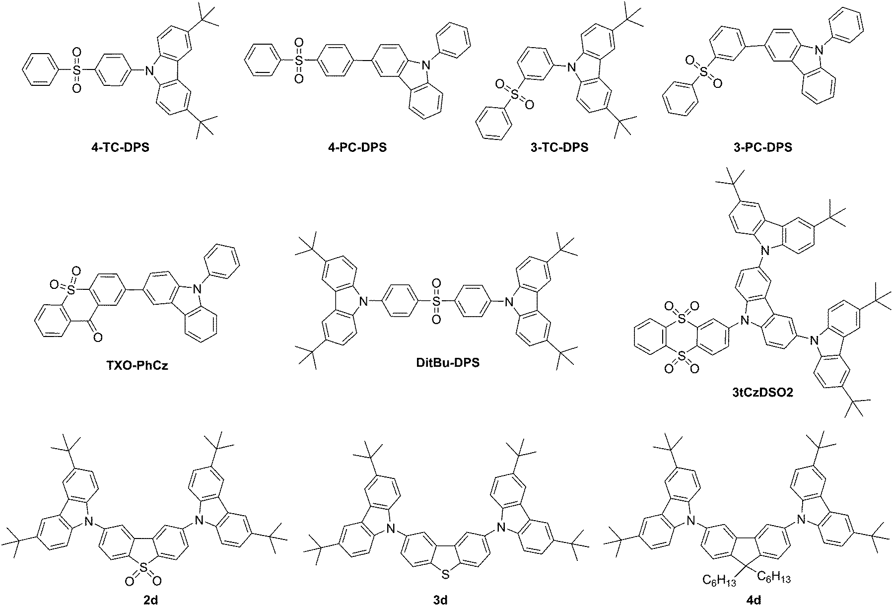
Zhang et al. presented three diphenylsulfone-based TADF materials as pure blue emitters, one of which contained carbazole as a building block with DitBu-DPS, Fig. 3.123 The CIE coordinates of the EL for a device based on this materials are (0.15, 0.07), close to the National Television Standards Committee (NTSC) standard blue with CIE coordinates of (0.14, 0.08). Blue fluorescent OLEDs with pure blue emission of CIEy > 0.1 are still difficult to achieve with transition metal-based PHOLED materials.
A carbazole-containing thioxanthon derivative, TXO-PhCz (Fig. 3) was prepared by Wang et al.59 Doping of emitters in a suitable host is a crucial and challenging process in the formation of TADF devices. Meng et al.124 utilized TXO-PhCz to prepare a multiquantum well structure in the emitting layer to create a nondoped TADF-based OLED with an EQE of 22.6%.
Sun et al.125 prepared tCzDPSO2, a molecule that showed only aggregation-induced emission. Replacing one single unit of carbazole with triscarbazole resulted in 3tCzDSO2 (Fig. 3), a chromophore that in addition to aggregation-induced emission showed TADF behavior.
Huang et al. prepared TADF materials utilizing carbazole donors and diphenylsulfone acceptors, 4-TC-DPS, 4-PC-DPS, 3-TC-DPS and 3-PC-DPS (Fig. 3); however, no device data was aquired.126 Only 3-TC-DPS and 4-TC-DPS had singlet–triplet splittings at or below 0.24 eV.
Dias et al. completed a study of donor–acceptor–donor (DAD) and donor–donor–donor compounds with a range of donor and acceptor units. Carbazole-containing compounds 2d, 3d, and 4d showed TADF behavior, Fig. 3.57 The group showed that even with singlet–triplet gaps (1CT–3ππ*) of more than 0.3 eV a TADF efficiency of unity can be achieved. Significantly, a linearly disubstituted acceptor unit leads to weak phosphorescence independent of the donor and acceptor units applied. Only compound 2d containing the dibenzothiophene-S,S-dioxide acceptor shows pure TADF behavior in the absence of TTA.
Chang et al. developed carbazole-triazine derivative CzT (Fig. 4) to serve as a host material for green PHOLEDs.127 Due to the presence of special separation of the HOMO–LUMO orbitals as investigated by density functional theory (DFT) calculations, Serevičius et al. utilized CzT and a derivative PhCzTAZ for TADF applications.128 Even though both molecules CzT and PhCzTAZ contain carbazole and triazine units, only CzT exhibited TADF behavior while PhCzTAZ did not. PhCzTAZ has a large singlet–triplet energy gap of 0.48 eV and 0.2 eV in hexane and toluene, respectively explaining the absence of TADF behavior. The molecule CzT exhibits solvent polarity dependent state switching for the singlet states between LE (hexane) and ICT (toluene). The singlet–triplet energy gap is observed as 0.085 eV in hexane and 0.008 eV in toluene.
The second approach utilizing benzofuran-fused carbazoles, i.e. a benzofurocarbazole donor with a diphenyltriazine acceptor to prepare blue emitters was presented by Lee et al.129 The o- vs. m- vs. p-linkages via a phenyl group resulted in compounds oBFCzTrz, mBFCzTrz, and pBFCzTrz (Fig. 4), which showed singlet–triplet energy gaps of 0.05, 0.11, and 0.25 eV, respectively. The o-linked material also showed a quantum efficiency of 20% and minimal efficiency roll-off.
Lee et al.145 raised the EQE for green and blue TADF devices up to 25% by evenly dispersing the HOMO of the TADF emitter over the entire donor unit with the concept of repeating the same donor unit multiple times. The compounds included DCzmCzTrz (first reported by Kim et al.130), TCzTrz, and TmCzTrz, Fig. 4. In addition, the optimization of the dopant concentration led to balanced hole and electron levels thus resulting in improved hole injection.
In search for strong donor moieties, Yoo et al. utilized two differently fused indoloacridines [2,3-b] vs. [2,3-c] entitled 3IA and 4IA, respectively, which were the basis for new materials 3DPTIA and 4DPTIA, Fig. 4.131 Based on computational modeling, 4IA was expected to experience steric hindrance in line with a TICT.26,27 Consequently, it was shown that only 4DPTIA exhibited TADF behavior, while 4IA was a stronger donor unit compared to 3IA. Both 4DPTIA and 3DPTIA were characterized as facilitating hole-transport.
Mayr et al. identified that alignment of dipole moments of emitting molecules such as CC2TA (Fig. 4) along with the inclusion of TADF capability significantly increases the external quantum efficiency beyond the typical limit of OLED devices.56
High singlet–triplet splitting is attributed to the phenyl linker, which serves to connect the carbazole-donor with a diphenyltriazine acceptor in TADF materials. Thus, an effort to minimize this splitting in blue emitters was applied by Kim et al. by utilizing 1-carbazolylcarbazole as opposed to 3-carbazolylcarbazole as the donor molecule in linker-free 1CzCzTrz, 3CzCzTrz, and 13CzCzTrz (Fig. 4) for blue TADF emitters.132 The carbazole substituent at the 1-position led to a twisting of the dihedral angle to 50° between the carbazole donor and the diphenyltriazine acceptor, which was not present at the 3-position, wherein a dihedral angle of 18° was observed in the optimized geometries (B3LYP/6-31G(d) level of theory). This observation was attributed to the increase in triplet energy and an observed singlet–triplet split of 0.03 eV (1CzCzTrz), 0.12 eV (3CzCzTrz), and 0.01 eV (13CzCzTrz). The FWHMs were reported as 74, 78, and 93 nm for the three compounds, respectively.
The TICT concept was applied for the second type of fused carbazole, i.e. phenylindolo[2,3-a]carbazole as applied in PIC-TRZ, which was created by Endo et al.,5Fig. 4. A material with a small ΔEST was realized along with a high kr ∼ 107.
As noted above, Kim et al. linked 3,3′-bicarbazole donors also to a triphenyltriazine core (TrzBCz, Fig. 4) to create a stable blue emitter of more than 23% efficiency as indicated above.121
Kim et al. introduced biscarbazole donor units entitled twin emitting cores into new TADF emitters with 2,3-, 3,3-, and 3,4-linkeages between the biscarbazole units coupled to a diphenyltriazine acceptor unit to form 23TCzTTrz, 33TCzTTrz, and 34TCzTTrz, Fig. 5.133 The group showed that 3,3′-bicarbazole more effectively lowers the singlet–tiplet gap and the highest quantum efficiency of 25% was observed for the greenish/blue TADF device.
Obolda et al. created TPA-TAZ and TCP, Fig. 5. Both materials exhibit higher than 25% singlet exciton formation, which could not be attributed to TTA, TADF or higher-level RISC, yet a triplet polaron-interaction-induced upconversion involving one-electron transfer mechanism was proposed.134
Sasabe et al.135 introduced a terpyridine unit in combination with an acridine core for TADF applications. When modulated with carbazole units, TADF material AcCz-2TP was prepared with a singlet triplet gap of 0.23 eV, Fig. 5.
Data et al. utilized dibenzo[a,j]phenazine (DBPHZ) as the acceptor unit and prepared several new TADF materials. When flanked with t-butylated carbazole donors, the material t-BuCZ-DBPHZ (Fig. 5) was prepared as a green to deep-red/NIR OLED emitter.29 The compound did not show significant CT emission until THF was applied as the solvent medium. Delayed fluorescence was weak and mostly phosphorescence was observed. A significant amount of TTA could not be excluded. In this case, intersystem crossing leading to the observed TADF is based on spin orbit charge transfer between the 1CT state and the triplet locally excited state on the acceptor (3LEA) instead of the general case of the donor. A long lived delayed fluorescence lifetime combined with TTA was attributed to the low device efficiencies.
Cai et al. attempted to reduce kR and kRISC by increasing the dihedral angles between the donor and acceptor systems involved and utilizing a molecular design including the TICT. The group combined t-butylated carbazoles as donor molecules (TC) and utilized benzil to induce a small kr on account of n–π* transition and a small ΔEST to create DC-TC, and converted the benzil group to dicyanopyrazine to create a new diazaring for a TADF molecule entitled PyCN-TC (Fig. 5). Both compounds follow the donor–π–acceptor–π–donor design. Along with 9,10-dihydroacridine building blocks, the group completed a thorough study of the photophysical, quantum chemical and OLED characteristics.136 Incidentally, PyCN-TC showed the lowest energy 3LE state, while DC-TC showed the lowest 3CT state. Zhang et al. showed that a lower lying 3LE enlarges ΔEST and hinders the efficiency of RISC processes.123 In the case of PyCN-TC, this leads to ΔEST of 0.46 eV and an increase of triplet exciton population. Taking all of the photophysical data together indicates the value of kRISC as the rate limiting factor in the exciton dynamic process and therefore the key factor for shortening τTADF. In device geometry, the larger kRISC leads to low efficiency roll-off characteristics.
Takahashi et al. chose 1,4-diazatriphenylene with a sufficiently high T1 energy level of 2.9 eV as the core to develop a TADF material and coupled it with the donor 3-(diphenylamino)carbazole in a D–A–D-type fashion to yield a sky-blue emitter m-ATP-CDP, Fig. 5.137
Shiu et al. introduced a non-carbon based linker to create a TADF material with a minimal orbital overlap between donor and acceptor units. The group applied the rigid, electron-accepting boron atom as a spiro-linker between the pyridyl pyrrolidine and carbazole donor units to create new boron complexes PrFPCz and PrFCzP for TADF applications, Fig. 6.138 TADF behavior was not observed for PrFPCz in toluene and related polar solvents, yet it was observed in the solid state.
The compound o-carborane is an electron-deficient boron-cluster, which was utilized by Furue et al. along with carbazole and triazine to create one D–A–A′ triad PCz-CB-TRZ as well as along with two phenyl-substituted carbazoles to create a D–A–D triad 2PCZ-CB,139Fig. 6. o-Carborane among other compounds is known to induce aggregation-induced emission, i.e. the chromophore is not emissive in dilute solutions; however, it is highly emissive in concentrated solutions. Aggregation-induce delayed fluorescence (AIDF) is triggered through the structural design of minimal HOMO–LUMO orbital overlap, which leads to a small singlet–triplet energy gap and thus opens the channel for thermal repopulation of the singlet excited state via AIDF behavior. The higher turn-on voltage for PCz-CB-TRZ is due to the larger hole-injection barrier, since the HOMO energy level is lower. The high external EL quantum efficiency of >11% for PCz-CB-TRZ was utilized in a dopant-free OLED configuration.
The TADF-approach was also applied as a remedy for blue emitters for PHOLEDs. These emitters are particularly challenging due to the bond dissociation caused by the highly energetic triplet excitons vide supra. Zhu et al.140 attempted to utilize all electro-generated excitons by embedding the concept of TADF to PHOLED devices termed metal-assisted delayed fluorescence (MADF). One and two-carbazole-containing molecules, PdN3O and PdN3N (Fig. 6), were embedded in devices with efficient phosphorescence and delayed fluorescence processes, respectively. External quantum efficiencies of 20.4% and 20.9% were achieved for PdN3O and PdN3N, respectively, though a significant roll-off behavior was observed.140 The large efficiency roll-off was attributed to long triplet lifetimes and poor charge balance.
Particular challenges are still observed for blue TADF-based OLEDs. When screening D–A vs. D–A–D systems, one derivative showed an external quantum efficiency of 19.5% and reduced efficiency roll-off characteristics at high luminance. A methodical study revealed the co-requirement of pre-twisted intramolecular charge-transfer molecules and small singlet–triplet energy gap. The 3LE state needs to necessarily be higher in energy than the 3CT state.141 In addition, the first triplet energy levels of the blue TADF dyes are significantly higher than the PHOLED representatives, i.e. 2.9 eV or above.53 This requires that exciton diffusion is suppressed by electron blocking layers and a modification of the charge transport layer to ensure a balanced charge transport. These efforts lead to more complex device structures.
Roll-off behavior is a challenge in TADF devices. Roll-off behavior was addressed in the work of Cho et al.142 Considering that both Förster and Dexter mechanisms of energy transfer apply to TADF materials, the optimization of the emissive layer (EML) thickness by widening the trap-free recombination zone and optimizing the doping concentration led to a decrease in the roll-off behavior.
The roll-off behavior of TADF devices was also addressed through device architecture by Tsang and Adachi.143 The inclusion of ultrathin layers (2–3 nm) of 8-hydroxyquinolinato lithium (liq) between the EML and the hole blocking layer (HBL) as well as between the HBL and the electron transport layer (ETL) led to up to 16-fold extension of device lifetime in which 90% of the initial luminance is reached. Thermally stimulated current measurements allowed Tsang et al. to reason that the formation of deep traps leads to decomposition of the organic emitting material via exciton–polaron interactions and thus an increased drive voltage.
Chen et al. addressed the high drive voltage of TADF-based OLEDs by the development of a different device architecture and the utilization of a new, carbazole-based p-type material TXFCz. The device architecture is a two-layer active heterojunction.144
Polymer and dendrimer approaches
During TADF device preparation, careful mixing of the host:dopant ratio is required along with careful scrutiny of the possible phase-separation processes. This hurdle may be avoided by using solution-processed polymers with TADF properties. Dopant-free systems are based on a dendrimer approach based on a carbazole unit due to its (not the least) superior, amorphous film-forming abilities (Table 2).
A D–A type backbone (pCzBP) for the polymer was realized by Lee et al., Fig. 7.6 Therein, the butterfly-shaped benzophenone is linked via the nitrogen atom of carbazole to alkylated carbazoles. The HOMO is localized primarily on the carbazole unit, while the LUMO is localized on the benzophenone units and a small ΔEST of 0.16 eV is observed. A device with a high external quantum efficiency of 9.3% was realized.
Zhu et al. prepared a conjugated D–A type polymer (PAPCC and PAPTC), wherein the carbazole-containing donors are fixed only in the backbone, while the acceptors are affixed on the side-chains only. This grafting leads to a significantly small ΔEST due to the physical separation of the HOMO and LUMO, Fig. 7.146
A dendrimeric TADF emitter was developed by Li et al.147 Dendrimers CDE1 and CDE2 (Fig. 8) are characterized by a benzophenone molecule as the anchor, linked to two acridine units, which are substituted in the first and second generation with the nitrogen of the carbazole units. The carbazole units are substituted themselves in the 3,6 positions with t-butyl groups. Solution processed devices utilizing these dendrimers showed an EQE of 13.3% at 1000 cd m−2 and a low roll-off behavior. Emission in the devices combined the emission from TADF behavior as well as exciplex emission.
Carbazole units were used to encapsulate the DMAC-DPS emitter to synthesize new sulfonate and acridine-containing emitting TADF materials entitled CzDMAC-DPS and DCzDMAC-DPS (Fig. 8) by Luo et al.148 These new materials were solution-processable and utilized in non-doped devices with a peak EQE of 12.2% and CIE coordinates of 0.22, 0.44.
Dendrimers are oligomers characterized by exact branching and absolute molecular weight. Dendrimers can have the ability to insulate chromophores housed at the core. A dendrimeric approach containing a triphenyl-s-triazine core substituted with generations of carbazole units entitled G2TAZ, G3TAZ, and G4TAZ was presented by Albrecht et al. as the first, self-hosting TADF material, Fig. 9.149 TADF devices showed a maximum external quantum efficiency of 3.4% for G3TAZ.
Further triazine-containing dendrimers were prepared by Sun et al.150 The dendrimers TA-Cz and TA-3Cz (Fig. 9) carry peripheral alkylated carbazole and triscarbazoles. The introduction of additional phenyl groups between the core and the dendrons served to physically separate/isolate the core from the periphery and thus induce a small singlet–triplet splitting as well as isolating the core by an encapsulation mechanism. Only 2.4 V was utilized for the drive voltage and an EQE of 11.8% was achieved using TA-3Cz.
Sun et al.151 presented a solution-processable approach, with a cross-linkable host-precursor DV-CDBP and emitter-precursor DV-MOC-DPS, Fig. 10. Upon cross-linking at various ratios, the group prepared TADF devices and showed that a mass ratio of 1:0.09 of host to emitter yielded a device with the highest photoluminescence quantum yield of 0.71 and a maximum external quantum efficiency of 2%.
Carbazole-based host materials for TADF applications
Organic host materials for PHOLEDs including carbazole-based materials were thoroughly reviewed by Tao et al.152 The article highlights hole-transporting, electron-transporting and hybrid bipolar transport materials. A thorough representation of the application of these materials is presented in a tabulated format for host properties and device characteristics. Particular challenges remain in the creation of bipolar hosts for blue phosphors, including improvement of efficiency roll-off and the overall simplification of devices in general. Solution processability thereby is presented by way of polymers. Fundamentally, however, small oligomers are key to the development of efficient, stable PHOLED devices. In general, host materials are conductive environments that serve to avoid aggregation-induce quenching of the long-lived triplet excitons and an effective system for energy transfer between host and guest emitting species. Host materials applied to TADF applications are cited herein along with physical, spectroscopic and device characteristics, Table 3. The host material for TADF applications is an important component in TADF devices as it influences the electroluminescence, lifetime and fluorescence quantum yield.153 Design principles are common for materials toward first and second generation OLED applications such as high physical and morphological stability, good film-forming abilities, bipolar charge transport properties for balanced hole and electron densities in the emitting layer, as well as appropriate alignment of the HOMO and LUMO with adjacent layers to facilitate charge injection.17 The criteria specific to function as a host material for TADF applications require efficient spectral overlap with the dopant (TADF emitter), a higher triplet energy level (ET) compared to the dopant to avoid reverse energy transfer and a widened HOMO–LUMO energy gap (Eg) compared to the dopant so that charges get trapped significantly only on the dopant.20 Herein, the widened HOMO–LUMO gap is a significant drawback as this leads to increased drive voltage of the devices. The molecular design for high triplet energy includes building blocks with inherent high triplet energies (carbazole) and a handle on the π-conjugation length through modulation of the linker units and incorporation of distortions in the molecule.17 For bipolar charge transport properties, a strong intramolecular charge transfer between donor and acceptor units is needed, which may lower the triplet energy level. Bipolar charge transport is also needed for high emission efficiency and ensuring low efficiency roll-off. Thus, a disruption of the π-conjugation-based connectivity between the donor and acceptor units by insulating, saturated atoms (sp3-hybridized C or Si) or a twisted π-conjugated spacer is favorable154 for maintaining a triplet energy level and blocking of intramolecular electronic coupling, yet negatively effects carrier transport properties.155 The role of the host specifically serves to separate the emitting species to reduce the concentration of high energy excited state species to reduce loss processes through photophysical processes, notably triplet–triplet annihilation,19,136 and device efficiency, i.e. roll-off behavior.35The host serves as a matrix for the emitting species and thus phase-separation and crystallization are of concern to ensure device stability particularly upon heating as well as during device operation.156 These concerns were addressed by the development of dendrimeric self-host materials comprising a combination of host and emitting species as outlined below. The donor component in a host material is often based on carbazole or derivatives thereof due to its inherent high triplet energy (ET) and good hole transport ability.157 Of interest is the acid/base chemistry of the nitrogen at position 9, as well as the electrochemically active positions 3 and 6 of nascent carbazole vide supra.91,92 A range of non-carbazole-based hosts were developed specifically for TADF applications including twisted and spirocyclic phosphine oxides158 and acridine-based sulfones.159 In addition, Sandanayaka et al. highlight the significant role the host – as opposed to the emitter – plays in device stability – or the lack thereof.160
Known carbazole-based host materials include TCTA, CzSi, and CBP, which were utilized by Zhang et al. in TADF applications.141 TCTA161–163 is characterized by a high glass transition temperature of 151 °C.164 CzSi is known for a high glass-transition temperature of >131 °C and hole mobilities of 5 × 10⁻⁵ cm2 V−1 s−1.88,165 CBP is a widely used material10,166 which tends to crystallize, suffers from a low glass transition temperature of merely 62 °C,167 and has a known decomposition profile as investigated by Kondakov.168 In addition, the low triplet energy of 2.56 eV results in inefficient energy transfer from the host to the guest and thus to poor device characteristics.169
Tanaka et al. presented a wide-energy gap material of 3.26 eV and high T1 energy (2.92 eV) entitled 3,4-di(9H-carbazol-9-yl)benzonitrile (2CzBN170) for use in TADF applications originally as an emitter. Since no TADF activity was found, the research group utilized 2CzBN as a host in various devices.
Li et al. designed three host materials o-, m-, and p-CzCN17 and provided evidence that among the three constitutional isomers of o-, m-, and p-CzCN a balanced charge-carrier mobility as well as sufficiently high singlet and triplet energy level are additional factors leading to better TADF device performance for both m-, and o-CzCN compared to p-CzCN, Fig. 11.
Li et al.171 prepared bipolar host materials, several containing carbazole units for the p-type component and pyrazole for the n-type component in a ratio of 2:1 for o-CzDPz, m-CzDPz, and 3-CzDPz with a control compound of 1:1 ratio mCPDPz, Table 3. All materials exhibit high enough triplet energy to be hosts for all types of (RGB) emitters, Fig. 11.
Cho et al. introduced a universal host material entitled DCzDCN for both PHOLED and TADF applications and created a material with a similar HOMO energy level, however, a deeper LUMO level compared to other carbazole-based hosts. A device containing DCzDCN compared to CBP showed a decrease in turn-on voltage by 0.5 V, the absence of roll-off behavior, and a 20-fold improved lifetime coupled, however, with limited luminance since the device utilizing 4CzIPN (1,2,3,5-tetrakis(carbazol-9-yl)-4,6-dicyanobenzene) did not reach 1000 cd m−2, Fig. 11.172
Gaj et al.173 developed mCPSOB as a new host material for TADF applications characterized by ambipolar charge properties. Under the application of 4CzIPN as a TADF emitter, an EQE of 21.5% at the luminance value of 1000 cd m−2 was recorded. At the same time, a low roll-off at high current densities was recorded. This was attributed to the high energy level of the triplet state of mCPSOB (3.02 eV), which suppresses triplet exciton quenching, Fig. 11.
Host materials can be tuned by mixing as presented by Kim and Lee.33 The known host material mCP shows only a glass transition temperature of 65 °C, a HOMO/LUMO energy level of −5.68 eV/−2.17 eV and a triplet energy level of 2.9 eV.174,175 A mixed host system, however, with a deep HOMO level combined with a high singlet energy and triplet energy level was achieved by mixing mCP:BmPyPb. This allows for the suppression of exciton quenching. The system performed as an exciplex-free host system with the green emitting species 4CzIPN, Fig. 11 and Table 3.
Zhao et al. studied o-mCPBI, m-mCPBI, and p-mCPBI as host materials for TADF applications.176 In comparison to mCP, these new materials showed higher Tg and thus the presence of benzimidazole significantly improved the morphological stability. The geometric parameters of o- vs. m- vs. p-linkages modulated the photophysical properties and specifically the triplet state around the values of 3.00, 2.80, and 2.71 eV, respectively, Fig. 11.
Nishimoto et al. developed an organic–inorganic hybrid material hexakis(9H-carbazol-9-yl)cyclotriphosphazene (PzCz) (Fig. 11) to serve as a host material in TADF devices and 2,5-bis(carbazol-9-yl)-1,4-dicyanobenzene (CzTPN) as a blue-green TADF emitter.20PzCz is characterized by high triplet energy (ET = 3.0 eV) and showed external electroluminescence quantum efficiencies of 15–18% when combined with CzTPN and 4CzIPN, Fig. 11.
Ban et al. constructed dendrimeric structures as self-host TADF materials. The combination of host and emitting species on the dendrimeric molecule avoids phase separation.156,177Tz-Cz and Tz-3Cz177 molecules included alkyl chains to allow a non-conjugated linkage between the host and the emitting species, Fig. 11. This concept led to increased solubility, avoided crystallization, and improved charge transport and the insulation of the emissive core from the surrounding host material as was previously applied to PHOLED-hosts.178 For dendrimeric materials tbCz-SO and poCz-SO, Ban et al. combined t-butylcarbazoles and phosphine oxide carbazoles,156 wherein the phosphine oxide carbazoles afforded high thermal stability, balanced charge transport, and stable color purity, Fig. 12.
Kang et al.179 synthesized new, bipolar host materials containing carbazole, pyridoindole, and dibenzothiophene entitled ZDZ and ZDN for blue-emitting TADF applications. Utilizing the emitter 2CzPN, the host containing all aforementioned units, ZDN, exhibited an EQE of 25.7%. Among these, ZDN has very low current density attributed to a large kRISC along with charge balance. The improved performance of the ZDN host material is attributed to the smaller non-radiative decay rate in comparison to other host materials, Fig. 12.
Solution-processed host materials pCNBCzmMe, pCNBCzoCF3, and pCNBCzmCF3 (Fig. 12) were introduced by Cao et al.157 These new materials are based on bicarbazoles and Cao et al.157 were able to create new materials with improved solubility, electron-transport properties and electrochemical stability compared to nascent biscarbazole.
The application of benzimidazobenzothiazole in combination with carbazoles led to another type of bipolar host entitled 29Cz-BID-BT and 39Cz-BID-BT (Fig. 12) as developed by Cui et al.154 Therein, a disruption of the donor–acceptor π-conjugated system was achieved utilizing the sp3-hybridization of the nitrogen-atom of carbazole linked on the benzimidazobenzothiazole acceptor units. Cui et al.154 utilized DFT and triplet-spin density models to localize electron density firmly on the carbazole unit. Both hosts have high triplet energy levels of 3.02 eV and 3.04 eV, respectively. The group was able to prepare blue TADF devices with a high EQE of 20.8 and 20.4% with low efficiency roll-off, respectively.
Hosting blue-emitting TADF materials places specific requirements on the host materials such as high triplet energy that allows for exothermic triplet host-dopant energy transfer. Ding et al.180 investigated the special effects governing hosts by preparing new quaternary phosphine oxide hosts 9CzFDPESPO, and 9CzFDPEPO, which included π-conjugated extender systems for the former and for the latter, a doubling of the phosphine oxide units compared to 9CzFSPO,155 in which the electron mobility was found to be proportional to the number of phosphine oxide units present, Fig. 12. The high triplet energy of 3.0 eV was preserved and HOMO/LUMO energy levels of −6.1 eV and −2.5 eV were observed for effective energy transfer and carrier injection, which allowed for the observation of high external quantum efficiencies of 22.5% for 9CzFDPESPO.
Overall, newly developed host materials pivoted around high triplet energy, bipolar behavior and solution processability. New materials were designed by a variation of substitution patterns, and host property variation by mere mixing up to dendrimerization of emitters. Acceptor units included nitrile, pyrazole and its derivatives, sulfoxide, phosphine oxide, benzodithiophene, and benzimidazobenzothiazole.
Computational analysis as applied on materials for TADF applications
DFT181 computations have been utilized to model materials for TADF applications and along with the extension of time-dependent DFT to fundamentally understand the electronic and photophysical properties leading to TADF behavior. The observed charge-transfer nature of TADF materials along with the small singlet–triplet splitting of ≤0.1 eV requires a careful choice of the level of theory in order to achieve balance between efficiency (qualitative) and accuracy (quantitative). Standard exchange correlation functionals (SVWN, BLYP, or B3LYP) are known to underestimate excitation energies (HOMO–LUMO gap)182 due to a mismatched exchange correlation, electron self-interaction or delocalization error, derivative discontinuity or electron–electron potential at large distances. The incorrect asymptotic behavior observed in the orbital energies of the CT excited states is the result of a self-interaction problem. Thereby, the term electron-transfer self-interaction is used because the orbital that accepts the electron exhibits coulombic repulsion between both the accepting and donating orbitals, which is not present in the CT state, yet not canceled by the time-dependent density functional theory (TD-DFT) calculations except if exact exchange is present.A survey of literature presenting quantum-chemical calculations in the context of the synthesis of TADF materials and their characterization in TADF devices revealed that the B3LYP functional combined with the 6-31G(d) basis set predominates for geometry optimizations of the ground state and computations involving excited states. Other utilized functionals include CAM-B3LYP, M06, M06-2X, PBE0 (25% HF) and HF. The basis sets range from STO-3G, to 6-31+G(d), D98(d,p), 6-311+G(d,p), and cc-pVDZ, LANL2DZ, Table 4.
| Ref. | Ground state geometry optimization | TD-DFT for excited states | ||
|---|---|---|---|---|
| Functional | Basis set | Functional | Basis set | |
| a Semiempirical level (PM6) b No data related to these calculations is reported; 6-31G(d). c The reported basis set 6-31+(d) was corrected to 6-31+G(d). d The reported basis set 6-31(d) was corrected to 6-31G(d) as confirmed by the authors. e Tabulated data does not specify which particular functional was applied for the reported results of each compound. | ||||
| Albrecht et al.149 | HF, PM6a | 6-31G | ||
| Ding et al.180 | B3LYP | 6-31G(d) | B3LYP | 6-31G(d) |
| Huang et al.126 | B3LYP | 6-31G(d) | B3LYP | 6-31G(d) |
| Ishimatsu et al.183 | B3LYP | 6-31+G(d)c | ||
| Ishimatsu et al.184 | M06-2X | 6-31G(d) | M06-2X | 6-31G(d) |
| Kitamoto et al.185 | M06 | 6-31G(d) | M06 | 6-31G(d) |
| Komino et al.35 | B3LYP | 6-31G(d) | B3LYP | 6-31G(d)d |
| Lee et al.186 | B3LYP | 6-31G(d) | BLYP, MPW1B95, BMK, M062X, and M06HFe | 6-31G(d) |
| Lee et al.31 | CAM-B3LYP | cc-pVDZ | CAM-B3LYP | cc-pVDZ |
| Lee et al.49 | CAM-B3LYP | cc-pVDZ | CAM-B3LYP | cc-pVDZ |
| Li et al.187 | B3LYP | 6-31G(d) | ||
| Linfoot et al.188 | B3LYP | LANL2DZ | B3LYP | LANL2DZ |
| Liu et al.189 | B3LYP | 6-31G(d) | ||
| Lu et al.190 | PBE0 (25% HF) | cc-pVDZ | PBE0, B3LYP, CAM-B3LYP | cc-pVDZ |
| Mayr et al.56 | B3LYP | 6-31G(d,p) | B3LYP | 6-31+G(d,p) |
| Park et al.191 | B3LYP, PBE0 | 6-31G(d) | PBE0 | 6-31G(d) |
| Sagara et al.192 | PBE0 | 6-31G(d) | PBE0 | 6-31G(d) |
| Shizu et al.76 | M06-2X | cc-pVDZ | ||
| Shizu et al.193 | M06-2X | cc-pVDZ | M06-2X | cc-pVDZ |
| Shu et al.194 | B3LYP, then CAM-B3LYP | STO-3G then 6-31G(d,p) | CAM-B3LYP (TD, TDA) | 6-31G(d,p) |
| Tanaka et al.195 | CAM-B3LYP | cc-pVDZ | CAM-B3LYP | cc-pVDZ |
| Tanaka et al.37 | PBE0 | 6-31G(d) | PBE0 | 6-31G(d) |
| Tsai et al.41 | B3LYP | 6-311G(d) | ||
| Wang et al.196 | B3LYP | 6-31G(d) | B3LYP | 6-311+G(d) |
| Wu et al.197 | B3LYP | 6-31G(d) | ||
| Xie et al.198 | B3LYP | 6-31G(d,p) | M06-2X | 6-31G(d) |
| Zhang et al.47 | B3LYP | 6-31G(d) | B3LYP; optimal HF exchange method | 6-31G(d) |
| Zhang et al.123 | B3LYP | 6-31G(d) | B3LYP | 6-31G(d) |
| Zhao et al.176 | B3LYP | 6-31G(d) | ||
Tapping into the biological toolbox, Shu and Levine presented a computational, simulated evolution approach for the identification of fluorophores for OLED application under the caveat of TADF functionality namely small S1–T1 gap and large S1 transition dipole moment.194 The group applied a tree-based genetic algorithm with eight genetic optimizations utilizing a molecular space of candidate fluorophors utilizing parole, thiophene, furan, pyridine, pyridine, and benzene acceptor groups with cyan-, aldehyde, carboxyl-, trifluoromethyl and 2,2-dicyanoethenyl EWG and carbazolyl, phenothiazinyl, carbolinyl, thieno(3,2-b′-indolyl), and indolyl EDG. Initial optimizations were run at the B3LYP/STO-3G level of theory followed by optimization of S0 at the CAM-B3LYP/6-31G(d,p) level of theory and the T1 state computed at the RO-CAM-B3LYP/6-31G(d,p) level of theory and the S1 state at the CAM-B3LYP/6-31G(d,p) level of theory to compute the S1–T1 gap along with the S0–S1 transition dipole moment as utilized in the optimization. The limitation of using the CAM-B3LYP functional did not allow the assessment of the target compounds for emission wavelength and the S1 and T1 computed at S0 geometry rather than the Franck–Codon point – a notion leading to an expected error of <0.1 eV. A range of possible molecules is suggested with a need to include synthetic accessibility into the algorithm. On the selected 7518 molecules, Shu and Levine194 presented the known example of carbozolyl and dicyanobenzene examples as exploited by Uoyama et al.21 and pyridines bound to various electron donors (without withdrawing group), 3-cyano- or 3,5-dicyanopyridines bound to various electron donors, carbazolyl pyridines with carboxyl or aldehyde withdrawing groups as already explored by Tang et al.,199 carbazolyl cyanopyrazines, and phenothiazinyl 3,4-di(2,2-dicyanoethenyl)-furans.
Chen et al.200 tackled the experimental observation that DAD systems under special circumstances show singlet excitons exceeding the theoretical limit of 25% and deviate while having larger than recommended energy gaps. Under application of potential energy scans along donor–acceptor angles utilizing TD-DFT using the BMK functional combined with the 6-31G(d) basis set, the group identified conical intersections when the acceptors are at 90° where degenerate molecular geometries exist. At points close to 90°, the conical intersection is accessible and thermal energy is enough to couple T1 geometry with the conical intersection and thus allows non-adiabatic coupling to promote T1 → S1 RISC rendering the butterfly type chromophore important for TADF applications.
The following is an overview of comparative and benchmarking computational studies, which tackle the electronic and photophysical properties of carbazole-containing TADF materials, Table 5. Uoyama utilized DFT calculations to optimized geometries of the singlet ground (S0) and first excited state (S1) along with the first excited triplet (T1) state and thus to predict CDCB properties. The cyanogroup inhibits non-radiative deactivation and minimizes modifications to the geometries of S1 and T1.21 Chromatic tunability is integrated through the number and substituent pattern on the dangling carbazole units. Among the functionals PBE0, B3LYP, CAM-B3LYP, wB97X-D and M06-2X that were utilized, the latter parameters performed best for absorption wavelength, singlet–triplet energy gap, charge transfer character and geometric features of dihedral angles between geometries, Table 5.
| Ref. | Functional(s) | Basis set(s) |
|---|---|---|
| Uoyama et al.21 | PBE0 (25% HF), B3LYP, CAM-B3LYP, ωB97X-D, M06-2X | 6-31G(d) |
| Moral et al.201 | PBE0, B2-PLYP, B2GP-PLYP | 6-31G(d), def2-TZVP, def2-TZVP/JK and def2-TZVP/C |
| Penfold et al.202 | PBE with Grimme’s D3 dispersion scheme and Becke–Johnson damping scheme | def2-TZVP (def2-SVP for H) |
| Liang et al.22 | B3LYP (20% HF) compared to BLYP (0% HF), MPWLYP1M (5% HF), B3LYP* (15% HF), PBE0, MPW1B95 (31% HF), BMK (42% HF), M06-2X (56% HF), M06-2X (56% HF), M06-HF (100% HF); excited states at (CAM-B3LYP, ωB97X-D); OHF-method | 6-31G(d) |
| Huang et al.203 | BLYP (0% HF), MPWLYP1M (5% HF), TPSSh (10% HF), B3LYP (15% HF), B3LYP (20% HF), PBE0, MPW1B95 (31%HF), BMK (42% HF), M06-2X (56% HF), M06-HF (100% HF); Cam-B3LYP, LC-ωPBE, ωB97X-D, LC-BYLP; OHF method | 6-31G(d) |
| Zhang et al.141 | B3LYP, PBE0, MPW1B95, BMK, M06-2X and M06-HF | 6-31G(d) |
| Sun et al.204 | PBE (0% HF), B3LYP (20% HF), M062X (56% HF), M06-HF (100% HF) as well as CAM-B3LYP, LC-ωPBE, ωB97X-D | 6-31G(d) to 6-31+G(d), 6-311G(d), 6-311+G(d), and 6-311++G(d,p) |
Moral et al. specifically explored the singlet–triplet energy gap in OLED materials with particular care on studying the charge-transfer character of the materials employed by identifying and validating a theoretical model, bracketing the influence on calculations and analyzing which excitations led to the singlet and triplet states obtained.201 The ground state geometry is best modeled using a large basis set and dispersion correction, i.e. the PBE0-D3(BJ)/def2-TZVP level of theory. The EVA(S1) and EVA(T1) were modeled utilizing a Tamm–Dancoff approximation (TDA) approach, which showed a negligible effect on EVA(S1) up to 0.11 eV and a significant effect on EVA(T1) up to 0.4 eV independent on functional choice (TDA-PBE0/6-31G(d) vs. TDA-B3LYP/6-31G(d)). The impact, thus, transpires to ΔEST with an improved maximum deviation from 0.58 eV to 0.23 eV. Intramolecular dispersion effects did not affect the ground state geometry with a maximum deviation of 0.01 eV, however, the larger basis sets (def2-TZVP and def2-QZVP) modulate E(S1) by ±0.1 eV yet to a smaller degree for E(T1) with ±0.05 eV, where a convergence with the smaller, less costly def2-TZVP basis set was shown.
Comparison with experimental values based on the onset of absorption and emission spectra necessitates the comparison with E00(S1) and E00(T1), respectively where the application of PBE0-D2(BJ)/def2-TZVP showed a close agreement between experimental and theoretical values with MAD and RMSD of 0.1 and 0.06 eV. Obtaining E00(S1) showed convergence problems. Immersed in a solvent environment, molecules with CT component require the non-equilibrium polarizable continuum model (PCM) leading to MAD and RMSD of 0.11 and 0.13. A completed natural transition orbital (NTO) analysis keeps the excitation energies the same, however, does compact all the transitions associated with an excitation to one single electron–hole pair. Using this approach, an electron–hole distance Δr was computed and a cutoff-value of >1.5–2 Å used to determine the presence of a CT excitation and an inverse relationship between distance and ΔEST values.205,206
Penfold202 surveyed 31 molecules for overlap between the HOMO and LUMO to develop a qualitative approach for predicting the singlet–triplet energy gap for effective computational screening of TADF materials. In a second approach, optimally tuned range-separated LC-BLYP functionals were utilized to quantitatively assess ΔEST and oscillator strength.
Noteworthy in this context is the work of Liang et al.,22 who focused on using DFT and TD-DFT to calculate the ΔEST for carbazole-based TADF emitters. Carbazole-based TADF-emitters undergo significant structural relaxation upon excitation to the singlet and triplet excited states with relaxational energies ranging from 0.4 to 0.5 eV for the singlet excited state and 0.1 to 0.2 eV for the triplet excited state. Using the adiabatic excitation method, Liang et al.22 were able to show that the functional B3LYP and basis set 6-31G(d) was sufficient to model the ΔEST for a series of carbazole-based TADF emitters deviating by only 0.00 eV to 0.02 eV from the experimental data since the substantial relaxation effects are accounted for, values that are significantly smaller in comparison to the optimal Hartree–Fock (OHF) method with deviation from 0.3 to 0.4 eV. A comparison of the adiabatic method along a broad range of functionals demonstrated that functionals with more than 25% HF are not suitable (PBE0, MPW1B95, BMK), long-range corrected functionals overestimate adiabatic ΔEST since the intramolecular CT transitions are shorter-ranged and the results of BLYP, MWLYP1M, and B3LYP* (<20% HF exchange) are close to the experimental values, however, these functionals underestimate E00(S1) and E00(T1). B3LYP* indicates 15% HF exchange. The OHF method localizes the lowest energy excited state as LE, while the lowest excited triplet state is of CT nature, which can only correctly be modeled using the adiabatic method. Thus, B3LYP (20% HF exchange) along with the 6-31G(d) basis set under application of the adiabatic method results in theoretically calculated values for ΔEST closest to experimental values for carbazole-based TADF emitters, Table 5.
Huang et al.203 explored the computational prediction of singlet- and triplet-transition energies for charge-transfer compounds. Pure TD-DFT functionals do not consider electrostatic interactions between the separated charges in the CT states. Thus, a detailed exploration to determine the optimal percentage of Hartree–Fock (OHF) in the TD-DFT calculation of EVA(S1) was carried out. The influence of the HF exchange percentage (%HF) in XC functionals on the calculated EVA(S1) was observed by screening 10 functionals ranging from 0% to 100% HF in correlation to the charge-transfer amount (q). The value of “q” was determined using orbital composition analysis.207 A series of 17 compounds were screened. Based on experimental data, the best %HF was assigned. Overall, the OHF equals 42q and the relative error of vertical transition energy for each functional is dependent on the CT amount. Since the CT state is always more polar than the ground state, calculation of EVE is carried out in the aromatic solvent toluene. Overall, reproduction of experimental data is achieved with an error of ±0.06 eV.
The prediction of T1 is difficult as this triplet state may be a CT or LE state founded in either the donor or acceptor. Evaluation of CT vs. LE states was achieved by studying the change in EVA(S1)–EVA(T1) as a function of %HF and an independent calculation of E0–0(3CT) and (3LE). The assumption that 3CT and 1CT have the same orbital transitions and the same CT amount allows an error correction to be developed using E0–0(3CT) = E0–0(S1) − [EVA(S1,OHF) − C × EVA(T1,BLYP)]. In this formula, C = EVA(S1,OHF)/EVA(S1,BLYP). The correction factor C was also applied in the correction for the LE state using the formula E0–0(3LE) = [EVA(T1/C)] − ΔEStokes. This procedure allowed for an effective identification of LE vs. CT states in good agreement with the experimental data. The group reported that range-separated hybrid functionals (CAM-B3LYP, LC-ωPBE, wB97XD and LC-BLYP) dramatically overestimate the EVA(S1) in the studied molecular group.
Hybrid functionals are used in DFT as approximations to the exchange and correlation energy terms. Therein, DFT and exact Hartree–Fock (HF) exchange energies are utilized. CT states in molecules are generally more sensitive to the percent of Hartree–Fock than LE states. Zhang et al.141 optimized structures with the B3LYP functional and the 6-31G(d) basis set. Thereby, a percent of Hartree–Fock close to OHF was utilized in order to calculate the change in energy during non-adiabatic (vertical) excitation from S0 to S1. The OHF ratio equal to 42q203 was utilized. Only a minimal difference in the CT amount q is observed for the S0 and S1 geometries in ICT molecules and therefore the group applied the geometry optimization of S1 utilizing a functional with a HF% close to OHF for calculations involving vertical absorption energy from S0 to S1 (EVA(S1)) to minimize error.
Sun et al.204 have explored the use of tuned range-separated functionals to calculate the singlet–triplet gap in a wide range of organic emitters including emitters for TADF applications to overcome the limitations of standard exchange functionals vide supra. The observed charge-transfer in TADF systems was studied using range-separated exchange density functionals for TD-DFT calculations under the application of an empirical tuning process for the range separation parameter omega (ω).208 Ground state geometries were optimized using the B3LYP/6-31G(d) level of theory and the range separation parameter omega was optimally tuned for the LC-ωPBE functional with the 6-31+G(d) basis set. Considering the vertical excitation processes, the lowest singlet EVA(S1) and triplet EVA(T1) excited states and vertical single–triplet gaps ΔEST. In addition, adiabatic singlet–triplet gaps ΔEST* were determined for three groups of model compounds showing singlet–triplet gaps categorized as large gaps such as PhCz and CBP [0.55–0.8 eV], moderate gaps such as PIC-TRZ, DTC-DPS, CC2TA, 2CzPN, and 4CzPN [0.15–0.5 eV] and very small gaps such as 4CzIPN, 4CzTPN, and 4CzTPN-Me [0.00–0.10 eV]. In the above mentioned range of compounds, only carbazole-containing materials were chosen. The group investigated functionals including pure GGA, PBE (0% eX), hybrid GGA: B3LYP (20% eX), meta GGA functionals M062X (56% eX) and M06HF (100% eX) as well as three range-separated functionals LC-ωPBE and ωB97XD and CAM-B3LYP with short-range ∼ long range eX% ranging from 19–65%, 0–100%, and 22–100%, respectively. A range of basis sets from 6-31G(d) to 6-31+G(d), 6-311G(d), 6-311+G(d), and 6-311++G(d,p) were employed. Fundamentally, the 6-31+G(d) basis set exhibited good accuracy associated with a moderate computational cost. The range separation parameter omega (ω) is unaffected by basis set extension from 6-31G(d) to 6-31+G(d). For comparison with experimental values derived from delayed fluorescence or phosphorescence spectra taken in solution (usually in toluene), CAM-B3LYP and UCAM-B3LYP along with the PCM model (toluene) were applied for calculation of adiabatic singlet–triplet gaps ΔEST*. When comparing TD-DFT vs. TDA-DFT calculations for tuned LC-ωPBE* functionals, the TDA approach shows improved description of ΔEST due to the better description of the triplet excitation energies along with lower computational costs and increased stability209 during computation of ΔEST. A direct comparison of the results of TD-DFT calculations using the B3LYP/6-31G(d) level of theory optimized in the ground state followed by the LC-ωPBE/6-31G(d) level of theory for TD/TDA-DFT computations with LC-ωPBE functional showed negligible differences.210
A thorough analysis of mean absolute deviation (MAD), relative error (RE), and linear correlation coefficients (R2) and a contrast to high level calculations using coupled cluster CC2 theory and double-hybrid functionals such as that completed by Moral et al.201 concludes that optimally tuned RC functionals such as the tuned LC-ωPBE functional deliver accurate results at reasonable computational costs as exemplified by the MAD of only 0.15, 0.07, and 0.09 for the calculated EVA(S1), ΔEST, and ΔEST*, respectively, when compared to the experimental values in toluene. Tian et al.211 reviewed several approaches contrasting the works of Huang et al.203 and Sun et al.204
Recently published work from the Brédas’212 research group computationally addressed kRISC, spin–orbit coupling (SOC), and ΔEST in a series of known and experimentally well-characterized TADF materials, i.e.2CzPN, CC2TA, PIC-TRZ, PXZ-TRZ, ACRFLCN, spiro-CN, 4CzIPN, 4CzIPN-Me, 4CzPN, 4CzTPN, and 4CzTPN-Me along with two non-TADF materials CBP, and α-NPD. The group utilized the B3LYP/6-31G(d) level of theory to optimize the ground state, CAM-B3LYP, as well as TD-DFT and uSCF for singlet and triplet excited state modeling, respectively under application of PCM for toluene. Optimal ω values were tuned and applied using the best performing range-separated LC-ωPBE/6-31+G(d) level of theory under application of TDA to compute excitation energies and LE vs. CT contributions. In addition, the SOC matrix was evaluated under application of the COSMOS continuum solvation model and LC-ωPBE functional as well as reorganization energies assessed under application of the DUSHIN program. Among other findings, the study concluded that the spatial separation of HOMO and LUMO are not the only factors contributing to a small ΔEST. Improvements are predicted to come from stabilizing the lowest energy triplet state as a charge-transfer state and strengthening the SOC so as to approach El-Sayed rule character in the system all the while ensuring a high PLQY. An outlook for experimental approaches and theoretical approaches to contribute further to the field is provided.
Conclusions and future outlook
While TADF-based OLED devices reach near 100% internal quantum efficiency, and an external quantum efficiency of 20–30%, current challenges in TADF-based OLED devices remain staggering. While the field is gaining momentum with the number of publications rising tremendously, there is still a tremendous need to address the challenge to achieve a low drive voltage at high quantum efficiency in order to optimize the device power efficiency, color purity and FWHM for blue emitters, as well as roll-off behavior. Part of this challenge is rooted in the fact that carbazole-containing TADF-emitting materials carry interrupted π-conjugation, which depresses charge mobility. Increasing conjugation, however, may compromise triplet energy. What is staggeringly absent is a broad, diverse range of materials with high stability and reliable luminescence. The presence of wide bandgap materials causes additional interface barriers and challenges in operating voltage of OLEDs, which should be close to the energy of the emitted photons. For a future outlook, the synthetic preparation of highly soluble, versatile, tunable organic materials will enable solution processing and ultimately the development of cheap, consumer-good devices; however, this solution processability is still in its infancy. A breakthrough, ultimately, in clever and deployable material design strategies will be enabled by a thorough understanding of the photophysics that drives the repopulation of the singlet excited state from the triplet state and a stabilization of the material in its triplet state during device operation, which is fundamentally rooted in smart device construction. This review shows the tremendous contribution carbazole-based materials have made to the field, both as emitters, and as hosts, wherein carbazole-containing host materials substituted particularly with benzimidazolbenzothiazole and phosphine oxides as acceptor units were shown to be successfully modulated for high triplet energy, solution processability, and devices exhibiting low efficiency roll-off. The localized triplet state of carbazole hosts, however, poses a significant challenge for hosting blue emitters. Exploring suitable doping levels and the inevitable risk of phase separation remain as challenges to be addressed for self-hosts. The interplay of experiments (synthesis and property determination), device construction and DFT-based studies tremendously aid in deepening the understanding and potentially the prediction of TADF properties for new materials. Although, currently, computational studies explore gas and condensed phases of single molecules, the effect of the bulk material should not be underestimated. Fundamental approaches such as the optimal Hartree–Fock Method and the application of optimally tuned range-separated functionals are viable tools to significantly improve the modeling of crucial properties such as the energy gap between the singlet and triplet states and separation of the frontier orbitals involved, and extend the understanding of the impact of the nature and energy level of excited states and the rates of photophysical properties, as well as the impact of spin–orbit coupling. With the tremendous global ongoing research efforts, the materialization of these efforts seems to be inching ever closer to soon becoming tangible.Acknowledgements
This work was supported by the Arab Fund Fellowship Program. The authors are grateful for this support. BW thanks the Lebanese American University School of Arts and Sciences for Faculty Development Fund (SRDC-p-2017-2). The authors greatly appreciate the thorough review by the four referees of this manuscript. The authors would like to thank Mr. Rami G. Abi Ammar for the help in designing the graphical abstract and the inside front cover.References
- M. A. Baldo, D. F. O'Brien, M. E. Thompson and S. R. Forrest, Phys. Rev. B: Condens. Matter Mater. Phys., 1999, 60, 14422–14428 CrossRef CAS.
- M. A. El-Sayed, Acc. Chem. Res., 1968, 1, 8–16 CrossRef CAS.
- C. Adachi, Jpn. J. Appl. Phys., 2014, 53, 060101 CrossRef.
- C. W. Tang and S. A. VanSlyke, Appl. Phys. Lett., 1987, 51, 913–915 CrossRef CAS.
- A. Endo, K. Sato, K. Yoshimura, T. Kai, A. Kawada, H. Miyazaki and C. Adachi, Appl. Phys. Lett., 2011, 98, 083302 CrossRef.
- S. Y. Lee, T. Yasuda, H. Komiyama, J. Lee and C. Adachi, Adv. Mater., 2016, 28, 4019–4024 CrossRef CAS PubMed.
- C. Adachi, M. A. Baldo, M. E. Thompson and S. R. Forrest, J. Appl. Phys., 2001, 90, 5048–5051 CrossRef CAS.
- H. Yersin and W. J. Finkenzeller, in Highly Efficient OLEDs with Phosphorescent Materials, ed. H. Yersin, Wiley-VCH Verlag GmbH & Co. KGaA, 2008, ch. 1, pp. 1–97 DOI:10.1002/9783527621309.
- Z. R. Li, Organic Light-Emitting Materials and Devices, CRC Press, 2nd edn, 2015 Search PubMed.
- M. A. Baldo, S. Lamansky, P. E. Burrows, M. E. Thompson and S. R. Forrest, Appl. Phys. Lett., 1999, 75, 4–6 CrossRef CAS.
- M. A. Baldo, D. F. O'Brien, Y. You, A. Shoustikov, S. Sibley, M. E. Thompson and S. R. Forrest, Nature, 1998, 395, 151–154 CrossRef CAS.
- Y.-L. Rao, D. Schoenmakers, Y.-L. Chang, J.-S. Lu, Z.-H. Lu, Y. Kang and S. Wang, Chem. – Eur. J., 2012, 18, 11306–11316 CrossRef CAS PubMed.
- H. Fukagawa, T. Shimizu, H. Hanashima, Y. Osada, M. Suzuki and H. Fujikake, Adv. Mater., 2012, 24, 5099–5103 CrossRef CAS PubMed.
- J.-L. Liao, Y. Chi, Y.-D. Su, H.-X. Huang, C.-H. Chang, S.-H. Liu, G.-H. Lee and P.-T. Chou, J. Mater. Chem. C, 2014, 2, 6269–6282 RSC.
- H. Xu, Q. Sun, Z. An, Y. Wei and X. Liu, Coord. Chem. Rev., 2015, 293–294, 228–249 CrossRef CAS.
- I. Oner, C. Sahin and C. Varlikli, Dyes Pigm., 2012, 95, 23–32 CrossRef CAS.
- W. Li, J. Li, D. Liu, F. Wang and S. Zhang, J. Mater. Chem. C, 2015, 3, 12529–12538 RSC.
- B. Valeur and M. N. Berberan-Santos, in Molecular Fluorescence: Principles and Applications, ed. B. Valeur and M. N. Berberan-Santos, Wiley-VCH Verlag GmbH & Co. KGaA, 2012, ch. 4, pp. 75–107 Search PubMed.
- D. Y. Kondakov, T. D. Pawlik, T. K. Hatwar and J. P. Spindler, J. Appl. Phys., 2009, 106, 124510 CrossRef.
- T. Nishimoto, T. Yasuda, S. Y. Lee, R. Kondo and C. Adachi, Mater. Horiz., 2014, 1, 264–269 RSC.
- H. Uoyama, K. Goushi, K. Shizu, H. Nomura and C. Adachi, Nature, 2012, 492, 234–238 CrossRef CAS PubMed.
- K. Liang, C. Zheng, K. Wang, W. Liu, Z. Guo, Y. Li and X. Zhang, Phys. Chem. Chem. Phys., 2016, 18, 26623–26629 RSC.
- N. J. Turro, Modern Molecular Photochemistry, Benjamin Cummings, 1978 Search PubMed.
- J. Saltiel, H. C. Curtis, L. Metts, J. W. Miley, J. Winterle and M. Wrighton, J. Am. Chem. Soc., 1970, 92, 410–411 CrossRef CAS.
- N. J. Turro, V. Ramamurthy and J. C. Scaiano, Modern Molecular Photochemistry of Organic Molecules, University Science Books, Sausalito, Calif, 2010 Search PubMed.
- Z. R. Grabowski, K. Rotkiewicz and W. Rettig, Chem. Rev., 2003, 103, 3899–4031 CrossRef PubMed.
- W. Rettig and E. A. Chandross, J. Am. Chem. Soc., 1985, 107, 5617–5624 CrossRef CAS.
- X. Cai, B. Gao, X.-L. Li, Y. Cao and S.-J. Su, Adv. Funct. Mater., 2016, 26, 8042–8052 CrossRef CAS.
- P. Data, P. Pander, M. Okazaki, Y. Takeda, S. Minakata and A. P. Monkman, Angew. Chem., Int. Ed., 2016, 55, 5739–5744 CrossRef CAS PubMed.
- (a) J. Lee, N. Aizawa, M. Numata, C. Adachi and T. Yasuda, Adv. Mater., 2017, 29, 1604856 CrossRef PubMed; (b) P. L. Santos, J. S. Ward, P. Data, A. S. Batsanov, M. R. Bryce, F. B. Dias and A. P. Monkman, J. Mater. Chem. C, 2016, 4, 3815–3824 RSC.
- J. Lee, K. Shizu, H. Tanaka, H. Nakanotani, T. Yasuda, H. Kaji and C. Adachi, J. Mater. Chem. C, 2015, 3, 2175–2181 RSC.
- D. R. Lee, S.-H. Hwang, S. K. Jeon, C. W. Lee and J. Y. Lee, Chem. Commun., 2015, 51, 8105–8107 RSC.
- B. S. Kim and J. Y. Lee, Adv. Funct. Mater., 2014, 24, 3970–3977 CrossRef CAS.
- M. A. Baldo, C. Adachi and S. R. Forrest, Phys. Rev. B: Condens. Matter Mater. Phys., 2000, 62, 10967–10977 CrossRef CAS.
- T. Komino, H. Nomura, T. Koyanagi and C. Adachi, Chem. Mater., 2013, 25, 3038–3047 CrossRef CAS.
- S. Reineke, K. Walzer and K. Leo, Phys. Rev. B: Condens. Matter Mater. Phys., 2007, 75, 125328 CrossRef.
- H. Tanaka, K. Shizu, H. Miyazaki and C. Adachi, Chem. Commun., 2012, 48, 11392–11394 RSC.
- D. Zhang, C. Zhao, Y. Zhang, X. Song, P. Wei, M. Cai and L. Duan, ACS Appl. Mater. Interfaces, 2017, 9, 4769–4777 CAS.
- R. Komatsu, H. Sasabe, Y. Seino, K. Nakao and J. Kido, J. Mater. Chem. C, 2016, 4, 2274–2278 RSC.
- L. Ding, S. C. Dong, Z. Q. Jiang, H. Chen and L. S. Liao, Adv. Funct. Mater., 2015, 25, 645–650 CrossRef CAS.
- W.-L. Tsai, M.-H. Huang, W.-K. Lee, Y.-J. Hsu, K.-C. Pan, Y.-H. Huang, H.-C. Ting, M. Sarma, Y.-Y. Ho, H.-C. Hu, C.-C. Chen, M.-T. Lee, K.-T. Wong and C.-C. Wu, Chem. Commun., 2015, 51, 13662–13665 RSC.
- I. H. Lee, W. Song and J. Y. Lee, Org. Electron., 2016, 29, 22–26 CrossRef CAS.
- H. Ohkuma, T. Nakagawa, K. Shizu, T. Yasuda and C. Adachi, Chem. Lett., 2014, 43, 1017–1019 CrossRef CAS.
- L.-S. Cui, Y.-M. Xie, Y.-K. Wang, C. Zhong, Y.-L. Deng, X.-Y. Liu, Z.-Q. Jiang and L.-S. Liao, Adv. Mater., 2015, 27, 4213–4217 CrossRef CAS PubMed.
- K. Nasu, T. Nakagawa, H. Nomura, C. J. Lin, C. H. Cheng, M. R. Tseng, T. Yasuda and C. Adachi, Chem. Commun., 2013, 49, 10385–10387 RSC.
- H. Ye, D. Chen, M. Liu, S.-J. Su, Y.-F. Wang, C.-C. Lo, A. Lien and J. Kido, Adv. Funct. Mater., 2014, 24, 3268–3275 CrossRef CAS.
- Q. Zhang, H. Kuwabara, W. J. Potscavage, S. Huang, Y. Hatae, T. Shibata and C. Adachi, J. Am. Chem. Soc., 2014, 136, 18070–18081 CrossRef CAS PubMed.
- X. He, D. Cai, D.-Y. Kang, W. Haske, Y. Zhang, C. A. Zuniga, B. H. Wunsch, S. Barlow, J. Leisen, D. Bucknall, B. Kippelen and S. R. Marder, J. Mater. Chem. C, 2014, 2, 6743–6751 RSC.
- J. Lee, K. Shizu, H. Tanaka, H. Nomura, T. Yasuda and C. Adachi, J. Mater. Chem. C, 2013, 1, 4599–4604 RSC.
- K. Goushi, K. Yoshida, K. Sato and C. Adachi, Nat. Photonics, 2012, 6, 253–258 CrossRef CAS.
- C. M. Han, Z. S. Zhang, H. Xu, J. Li, G. H. Xie, R. F. Chen, Y. Zhao and W. Huang, Angew. Chem., Int. Ed., 2012, 51, 10104–10108 CrossRef CAS PubMed.
- C. M. Han, L. P. Zhu, J. Li, F. C. Zhao, Z. Zhang, H. Xu, Z. P. Deng, D. G. Ma and P. F. Yan, Adv. Mater., 2014, 26, 7070–7077 CrossRef CAS PubMed.
- C. Fan, C. Duan, Y. Wei, D. Ding, H. Xu and W. Huang, Chem. Mater., 2015, 27, 5131–5140 CrossRef CAS.
- J. Li, Q. S. Zhang, H. Nomura, H. Miyazaki and C. Adachi, Appl. Phys. Lett., 2014, 105, 013301 CrossRef.
- H. Nakanotani, T. Higuchi, T. Furukawa, K. Masui, K. Morimoto, M. Numata, H. Tanaka, Y. Sagara, T. Yasuda and C. Adachi, Nat. Commun., 2014, 5, 4016 CAS.
- C. Mayr, S. Y. Lee, T. D. Schmidt, T. Yasuda, C. Adachi and W. Brutting, Adv. Funct. Mater., 2014, 24, 5232–5239 CrossRef CAS.
- F. B. Dias, K. N. Bourdakos, V. Jankus, K. C. Moss, K. T. Kamtekar, V. Bhalla, J. Santos, M. R. Bryce and A. P. Monkman, Adv. Mater., 2013, 25, 3707–3714 CrossRef CAS PubMed.
- S. Y. Lee, T. Yasuda, Y. S. Yang, Q. S. Zhang and C. Adachi, Angew. Chem., Int. Ed., 2014, 53, 6402–6406 CrossRef CAS PubMed.
- H. Wang, L. S. Xie, Q. Peng, L. Q. Meng, Y. Wang, Y. P. Yi and P. F. Wang, Adv. Mater., 2014, 26, 5198–5204 CrossRef CAS PubMed.
- J. Li, T. Nakagawa, Q. Zhang, H. Nomura, H. Miyazaki and C. Adachi, Adv. Mater., 2013, 25, 3319–3323 CrossRef CAS PubMed.
- X.-L. Chen, R. Yu, Q.-K. Zhang, L.-J. Zhou, X.-Y. Wu, Q. Zhang and C.-Z. Lu, Chem. Mater., 2013, 25, 3910–3920 CrossRef CAS.
- R. Czerwieniec and H. Yersin, Inorg. Chem., 2015, 54, 4322–4327 CrossRef CAS PubMed.
- N. Lin, J. Qiao, L. Duan, L. Wang and Y. Qiu, J. Phys. Chem. C, 2014, 118, 7569–7578 CAS.
- T. Yasuda, S. Y. Lee and C. Adachi, Kagaku to Kogyo, 2014, 88, 363–367 CAS.
- S. Wu, Yingxiang Kexue Yu Guang Huaxue, 2014, 32, 217–237 CAS.
- K. Shizu and C. Adachi, Kokagaku, 2014, 45, 25–28 CAS.
- K. Goshi, T. Nakagawa and C. Adachi, CSJ Curr. Rev., 2013, 12, 127–137 CAS.
- M. Taneda, H. Tanaka, K. Shizu, T. Nakagawa and C. Adachi, Kagaku Kogyo, 2014, 65, 1–8 CAS.
- K. Goshi, T. Uoyama, K. Shizu, H. Nomura and C. Adachi, Mol. Electron. Bioelectron., 2013, 24, 75–78 CAS.
- C. Adachi, Oyo Butsuri, 2013, 82, 458–464 CAS.
- C. Adachi and A. Endo, Kobunshi, 2009, 58, 797–800 CAS.
- Y. Tao, K. Yuan, T. Chen, P. Xu, H. Li, R. Chen, C. Zheng, L. Zhang and W. Huang, Adv. Mater., 2014, 26, 7931–7958 CrossRef CAS PubMed.
- L. Bergmann, D. M. Zink, S. Brase, T. Baumann and D. Volz, Top. Curr. Chem., 2016, 374, 22 CrossRef PubMed.
- M. J. Leitl, D. M. Zink, A. Schinabeck, T. Baumann, D. Volz and H. Yersin, Top. Curr. Chem., 2016, 374, 25 CrossRef PubMed.
- M. Y. Wong and E. Zysman-Colman, Adv. Mater., 2017, 29, 1605444 CrossRef PubMed.
- K. Shizu, J. Lee, H. Tanaka, H. Nomura, T. Yasuda, H. Kaji and C. Adachi, Pure Appl. Chem., 2015, 87, 627–638 CrossRef CAS.
- F. Dumur, Org. Electron., 2015, 25, 345–361 CrossRef CAS.
- N. Blouin and M. Leclerc, Acc. Chem. Res., 2008, 41, 1110–1119 CrossRef CAS PubMed.
- S. Beaupre and M. Leclerc, J. Mater. Chem. A, 2013, 1, 11097–11105 CAS.
- Chemistry of Heterocyclic Compounds, ed. W. G. Sumpter and F. M. Miller, John Wiley & Sons, Inc., 1954, vol. 8, pp. 70–109 Search PubMed.
- B. Benali, A. Kadiri and G. Nouchi, Spectrochim. Acta, Part A, 1992, 48, 733–741 CrossRef.
- H. Walba and G. E. K. Branch, J. Am. Chem. Soc., 1951, 73, 3341–3348 CrossRef CAS.
- A. Bree and R. Zwarich, J. Chem. Phys., 1968, 49, 3355–3358 CrossRef CAS.
- N. Mataga, Y. Torihashi and K. Ezumi, Theor. Chim. Acta, 1964, 2, 158–167 CrossRef CAS.
- G. E. Johnson, J. Phys. Chem., 1974, 78, 1512–1521 CrossRef CAS.
- J. B. Birks, Photophysics of Aromatic Molecules, Wiley-Interscience, London, 1970 Search PubMed.
- I. B. Berlman, Handbook of Fluorescence Spectra of Aromatic Molecules, Academic Press, New York, 1965 Search PubMed.
- M. H. Tsai, H. W. Lin, H. C. Su, T. H. Ke, C. C. Wu, F. C. Fang, Y. L. Liao, K. T. Wong and C. I. Wu, Adv. Mater., 2006, 18, 1216–1220 CrossRef CAS.
- J. R. Huber and J. E. Adams, Ber. Bunsenges. Phys. Chem., 1974, 78, 217–223 CAS.
- P. J. S. Gomes, C. Serpa and L. G. Arnaut, J. Photochem. Photobiol., A, 2006, 184, 228–233 CrossRef CAS.
- K. Karon and M. Lapkowski, J. Solid State Electrochem., 2015, 19, 2601–2610 CrossRef CAS.
- J. F. Ambrose and R. F. Nelson, J. Electrochem. Soc., 1968, 115, 1159–1164 CrossRef CAS.
- U.S. Department Of Energy Solid-State Lighting Program Collaborative R&D Testing Opportunity: Organic Light-Emitting Diodes Testing Application Guidelines, http://https://energy.gov/sites/prod/files/2017/02/f34/DOE_SSL_OLED_Testing_Application%20Guidelines_February%202017.pdf, accessed June 2017.
- Y. Seino, S. Inomata, H. Sasabe, Y.-J. Pu and J. Kido, Adv. Mater., 2016, 28, 2638–2643 CrossRef CAS.
- K. Masui, H. Nakanotani and C. Adachi, Org. Electron., 2013, 14, 2721–2726 CrossRef CAS.
- A. Kretzschmar, C. Patze, S. T. Schwaebel and U. H. F. Bunz, J. Org. Chem., 2015, 80, 9126–9131 CrossRef CAS.
- T. Furukawa, H. Nakanotani, M. Inoue and C. Adachi, Sci. Rep., 2015, 5, 8429 CrossRef CAS.
- J. W. Sun, K.-H. Kim, C.-K. Moon, J.-H. Lee and J.-J. Kim, ACS Appl. Mater. Interfaces, 2016, 8, 9806–9810 CAS.
- P. Wang, S. Zhao, Z. Xu, B. Qiao, Z. Long and Q. Huang, Molecules, 2016, 21, 1365 CrossRef.
- Y.-H. Kim, C. Wolf, H. Cho, S.-H. Jeong and T.-W. Lee, Adv. Mater., 2016, 28, 734–741 CrossRef CAS.
- Y. J. Cho, K. S. Yook and J. Y. Lee, Adv. Mater., 2014, 26, 6642–6646 CrossRef CAS.
- W. Liu, C.-J. Zheng, K. Wang, M. Zhang, D.-Y. Chen, S.-L. Tao, F. Li, Y.-P. Dong, C.-S. Lee, X.-M. Ou and X.-H. Zhang, ACS Appl. Mater. Interfaces, 2016, 8, 32984–32991 CAS.
- Z. Wu, J. Luo, N. Sun, L. Zhu, H. Sun, L. Yu, D. Yang, X. Qiao, J. Chen, C. Yang and D. Ma, Adv. Funct. Mater., 2016, 26, 3306–3313 CrossRef CAS.
- D. Zhang, M. Cai, Y. Zhang, D. Zhang and L. Duan, ACS Appl. Mater. Interfaces, 2015, 7, 28693–28700 CAS.
- B. S. Kim and J. Y. Lee, Org. Electron., 2015, 21, 100–105 CrossRef CAS.
- D. Zhang, L. Duan, Y. Li, D. Zhang and Y. Qiu, J. Mater. Chem. C, 2014, 2, 8191–8197 RSC.
- W. Y. Hung, G. C. Fang, S. W. Lin, S. H. Cheng, K. T. Wong, T. Y. Kuo and P. T. Chou, Sci. Rep., 2014, 4, 5161 CrossRef CAS PubMed.
- Y. J. Cho, K. S. Yook and J. Y. Lee, Sci. Rep., 2015, 5, 7859 CrossRef CAS PubMed.
- K. S. Yook, S. K. Jeon and J. Y. Lee, J. Lumin., 2016, 169, 266–269 CrossRef CAS.
- L. Mei, J. Hu, X. Cao, F. Wang, C. Zheng, Y. Tao, X. Zhang and W. Huang, Chem. Commun., 2015, 51, 13024–13027 RSC.
- D. Zhang, M. Cai, Y. Zhang, D. Zhang and L. Duan, Mater. Horiz., 2016, 3, 145–151 RSC.
- C. Tang, T. Yang, X. D. Cao, Y. T. Tao, F. F. Wang, C. Zhong, Y. Qian, X. W. Zhang and W. Huang, Adv. Opt. Mater., 2015, 3, 786–790 CrossRef CAS.
- J. Zhang, J. Li, W. Chen, D. Zheng, J. Yu, H. Wang and B. Xu, Tetrahedron Lett., 2016, 57, 2044–2048 CrossRef CAS.
- Y. J. Cho, S. K. Jeon and J. Y. Lee, Adv. Opt. Mater., 2016, 4, 688–693 CrossRef CAS.
- S. Tanimoto, T. Suzuki, H. Nakanotani and C. Adachi, Chem. Lett., 2016, 45, 770–772 CrossRef CAS.
- Y. J. Cho, S. K. Jeon, S.-S. Lee, E. Yu and J. Y. Lee, Chem. Mater., 2016, 28, 5400–5405 CrossRef CAS.
- Y. J. Cho, S. K. Jeon, B. D. Chin, E. Yu and J. Y. Lee, Angew. Chem., Int. Ed., 2015, 54, 5201–5204 CrossRef CAS PubMed.
- P. Rajamalli, N. Senthilkumar, P. Gandeepan, P.-Y. Huang, M.-J. Huang, M.-J. Chiu, L.-K. Chu, C.-H. Cheng, C.-Z. Ren-Wu, C.-Y. Yang and H.-W. Lin, J. Am. Chem. Soc., 2016, 138, 628–634 CrossRef CAS PubMed.
- P. Rajamalli, N. Senthilkumar, P. Gandeepan, C.-Z. Ren-Wu, H.-W. Lin and C.-H. Cheng, J. Mater. Chem. C, 2016, 4, 900–904 RSC.
- P. Rajamalli, N. Senthilkumar, P. Gandeepan, C.-C. Ren-Wu, H.-W. Lin and C.-H. Cheng, ACS Appl. Mater. Interfaces, 2016, 8, 27026–27034 CAS.
- H. M. Kim, J. M. Choi and J. Y. Lee, RSC Adv., 2016, 6, 64133–64139 RSC.
- J. Lee, I. S. Park and T. Yasuda, Bull. Chem. Soc. Jpn., 2017, 90, 231–236 CrossRef CAS.
- Q. Zhang, J. Li, K. Shizu, S. Huang, S. Hirata, H. Miyazaki and C. Adachi, J. Am. Chem. Soc., 2012, 134, 14706–14709 CrossRef CAS PubMed.
- L. Meng, H. Wang, X. Wei, J. Liu, Y. Chen, X. Kong, X. Lv, P. Wang and Y. Wang, ACS Appl. Mater. Interfaces, 2016, 8, 20955–20961 CAS.
- K. Sun, W. Jiang, X. Ban, B. Huang, Z. Zhang, M. Ye and Y. Sun, RSC Adv., 2016, 6, 22137–22143 RSC.
- B. Huang, W. Jiang, Y. Liu, Y. Zhang, Y. Yang, Y. Dai, X. Ban, H. Xu and Y. Sun, Adv. Mater. Res., 2014, 1044–1045, 158–163 CAS.
- C.-H. Chang, M.-C. Kuo, W.-C. Lin, Y.-T. Chen, K.-T. Wong, S.-H. Chou, E. Mondal, R. C. Kwong, S. Xia, T. Nakagawa and C. Adachi, J. Mater. Chem., 2012, 22, 3832–3838 RSC.
- T. Serevičius, T. Nakagawa, M.-C. Kuo, S.-H. Cheng, K.-T. Wong, C.-H. Chang, R. C. Kwong, S. Xia and C. Adachi, Phys. Chem. Chem. Phys., 2013, 15, 15850–15855 RSC.
- D. R. Lee, J. M. Choi, C. W. Lee and J. Y. Lee, ACS Appl. Mater. Interfaces, 2016, 8, 23190–23196 CAS.
- M. Kim, S. K. Jeon, S.-H. Hwang and J. Y. Lee, Adv. Mater., 2015, 27, 2515–2520 CrossRef CAS PubMed.
- S. G. Yoo, W. Song and J. Y. Lee, Dyes Pigm., 2016, 128, 201–208 CrossRef CAS.
- M. Kim, J. M. Choi and J. Y. Lee, Chem. Commun., 2016, 52, 10032–10035 RSC.
- M. Kim, S.-K. Jeon, S.-H. Hwang, S.-S. Lee, E. Yu and J. Y. Lee, J. Phys. Chem. C, 2016, 120, 2485–2493 CAS.
- A. Obolda, Q. Peng, C. He, T. Zhang, J. Ren, H. Ma, Z. Shuai and F. Li, Adv. Mater., 2016, 28, 4740–4746 CrossRef CAS PubMed.
- H. Sasabe, Y. Hayasaka, R. Komatsu, K. Nakao and J. Kido, Chem. – Eur. J., 2017, 23, 114–119 CrossRef CAS PubMed.
- X. Cai, X. Li, G. Xie, Z. He, K. Gao, K. Liu, D. Chen, Y. Cao and S.-J. Su, Chem. Sci., 2016, 7, 4264–4275 RSC.
- T. Takahashi, K. Togashi, K. Shizu, T. Yasuda and C. Adachi, Sci. Technol. Adv. Mater., 2014, 15, 034202 CrossRef PubMed.
- Y.-J. Shiu, Y.-C. Cheng, W.-L. Tsai, C.-C. Wu, C.-T. Chao, C.-W. Lu, Y. Chi, Y.-T. Chen, S.-H. Liu and P.-T. Chou, Angew. Chem., Int. Ed., 2016, 55, 3017–3021 CrossRef CAS PubMed.
- R. Furue, T. Nishimoto, I. S. Park, J. Lee and T. Yasuda, Angew. Chem., Int. Ed., 2016, 55, 7171–7175 CrossRef CAS PubMed.
- Z. Q. Zhu, T. Fleetham, E. Turner and J. Li, Adv. Mater., 2015, 27, 2533–2537 CrossRef CAS PubMed.
- Q. Zhang, B. Li, S. Huang, H. Nomura, H. Tanaka and C. Adachi, Nat. Photonics, 2014, 8, 326–332 CrossRef CAS.
- Y. R. Cho, S. J. Cha and M. C. Suh, Synth. Met., 2015, 209, 47–54 CrossRef CAS.
- D. P.-K. Tsang and C. Adachi, Sci. Rep., 2016, 6, 22463 CrossRef CAS PubMed.
- D. Chen, K. Liu, L. Gan, M. Liu, K. Gao, G. Xie, Y. Ma, Y. Cao and S.-J. Su, Adv. Mater., 2016, 28, 6758–6765 CrossRef CAS PubMed.
- D. R. Lee, M. Kim, S. K. Jeon, S.-H. Hwang, C. W. Lee and J. Y. Lee, Adv. Mater., 2015, 27, 5861–5867 CrossRef CAS PubMed.
- Y. Zhu, Y. Zhang, B. Yao, Y. Wang, Z. Zhang, H. Zhan, B. Zhang, Z. Xie, Y. Wang and Y. Cheng, Macromolecules, 2016, 49, 4373–4377 CrossRef CAS.
- Y. Li, G. Xie, S. Gong, K. Wu and C. Yang, Chem. Sci., 2016, 7, 5441–5447 RSC.
- J. Luo, S. Gong, Y. Gu, T. Chen, Y. Li, C. Zhong, G. Xie and C. Yang, J. Mater. Chem. C, 2016, 4, 2442–2446 RSC.
- K. Albrecht, K. Matsuoka, K. Fujita and K. Yamamoto, Angew. Chem., Int. Ed., 2015, 54, 5677–5682 CrossRef CAS PubMed.
- K. Sun, Y. Sun, T. Huang, J. Luo, W. Jiang and Y. Sun, Org. Electron., 2017, 42, 123–130 CrossRef CAS.
- K. Sun, X. Xie, Y. Liu, W. Jiang, X. Ban, B. Huang and Y. Sun, J. Mater. Chem. C, 2016, 4, 8973–8979 RSC.
- Y. Tao, C. Yang and J. Qin, Chem. Soc. Rev., 2011, 40, 2943–2970 RSC.
- G. Mehes, K. Goushi, W. J. Potscavage Jr. and C. Adachi, Org. Electron., 2014, 15, 2027–2037 CrossRef CAS.
- L.-S. Cui, J. U. Kim, H. Nomura, H. Nakanotani and C. Adachi, Angew. Chem., Int. Ed., 2016, 55, 6864–6868 CrossRef CAS PubMed.
- D. Yu, F. Zhao, C. Han, H. Xu, J. Li, Z. Zhang, Z. Deng, D. Ma and P. Yan, Adv. Mater., 2012, 24, 509–514 CrossRef CAS PubMed.
- X. Ban, B. Lin, W. Jiang and Y. Sun, Chem. – Asian J., 2016, 4, 8810–8816 CAS.
- X. Cao, J. Hu, Y. Tao, W. Yuan, J. Jin, X. Ma, X. Zhang and W. Huang, Dyes Pigm., 2017, 136, 543–552 CrossRef CAS.
- J. Li, D. Ding, Y. Tao, Y. Wei, R. Chen, L. Xie, W. Huang and H. Xu, Adv. Mater., 2016, 28, 3122–3130 CrossRef CAS PubMed.
- Z. Liu, Y. Lei, C. Fan, X. Peng, X. Ji, G. E. Jabbour and X. Yang, Org. Electron., 2017, 41, 237–244 CrossRef CAS.
- A. S. D. Sandanayaka, T. Matsushima and C. Adachi, J. Phys. Chem. C, 2015, 119, 23845–23851 CAS.
- D. H. Lee, Y. P. Liu, K. H. Lee, H. Chae and S. M. Cho, Org. Electron., 2010, 11, 427–433 CrossRef CAS.
- S. J. Su, E. Gonmori, H. Sasabe and J. Kido, Adv. Mater., 2008, 20, 4189–4194 CAS.
- S. H. Kim, J. Jang and J. Y. Lee, Appl. Phys. Lett., 2007, 91, 083511 CrossRef.
- Y. Shirota, J. Mater. Chem., 2000, 10, 1–25 RSC.
- M.-H. Tsai, T.-H. Ke, H.-W. Lin, C.-C. Wu, S.-F. Chiu, F.-C. Fang, Y.-L. Liao, K.-T. Wong, Y.-H. Chen and C.-I. Wu, ACS Appl. Mater. Interfaces, 2009, 1, 567–574 CAS.
- K. Goushi, R. Kwong, J. J. Brown, H. Sasabe and C. Adachi, J. Appl. Phys., 2004, 95, 7798–7802 CrossRef CAS.
- M.-H. Tsai, Y.-H. Hong, C.-H. Chang, H.-C. Su, C.-C. Wu, A. Matoliukstyte, J. Simokaitiene, S. Grigalevicius, J. V. Grazulevicius and C. P. Hsu, Adv. Mater., 2007, 19, 862–866 CrossRef CAS.
- D. Y. Kondakov, W. C. Lenhart and W. F. Nicholas, J. Appl. Phys., 2007, 101, 024512 CrossRef.
- C. Adachi, M. A. Baldo, S. R. Forrest, S. Lamansky, M. E. Thompson and R. C. Kwong, Appl. Phys. Lett., 2001, 78, 1622–1624 CrossRef CAS.
- Y. Tanaka, T. Takahashi, J. Nishide, Y. Hiraga, H. Nakanotani and C. Adachi, Thin Solid Films, 2016, 619, 120–124 CrossRef CAS.
- W. Li, J. Li, F. Wang, Z. Gao and S. Zhang, ACS Appl. Mater. Interfaces, 2015, 7, 26206–26216 CAS.
- Y. J. Cho, K. S. Yook and J. Y. Lee, Adv. Mater., 2014, 26, 4050–4055 CrossRef CAS PubMed.
- M. P. Gaj, C. Fuentes-Hernandez, Y. Zhang, S. R. Marder and B. Kippelen, Org. Electron., 2015, 16, 109–112 CrossRef CAS.
- V. Adamovich, J. Brooks, A. Tamayo, A. M. Alexander, P. I. Djurovich, B. W. D'Andrade, C. Adachi, S. R. Forrest and M. E. Thompson, New J. Chem., 2002, 26, 1171–1178 RSC.
- R. J. Holmes, S. R. Forrest, Y. J. Tung, R. C. Kwong, J. J. Brown, S. Garon and M. E. Thompson, Appl. Phys. Lett., 2003, 82, 2422–2424 CrossRef CAS.
- Y. Zhao, C. Wu, P. Qiu, X. Li, Q. Wang, J. Chen and D. Ma, ACS Appl. Mater. Interfaces, 2016, 8, 2635–2643 CAS.
- X. Ban, W. Jiang, T. Lu, X. Jing, Q. Tang, S. Huang, K. Sun, B. Huang, B. Lin and Y. Sun, J. Mater. Chem. C, 2016, 4, 8810–8816 RSC.
- H. Xu, D. H. Yu, L. L. Liu, P. F. Yan, L. W. Jia, G. M. Li and Z. Y. Yue, J. Phys. Chem. B, 2010, 114, 141–150 CrossRef CAS PubMed.
- J. S. Kang, T. R. Hong, H. J. Kim, Y. H. Son, R. Lampande, B. Y. Kang, C. Lee, J.-K. Bin, B. S. Lee, J. H. Yang, J. Kim, S. Park, M. J. Cho, J. H. Kwon and D. H. Choi, J. Mater. Chem. C, 2016, 4, 4512–4520 RSC.
- D. Ding, Z. Zhang, Y. Wei, P. Yan and H. Xu, J. Mater. Chem. C, 2015, 3, 11385–11396 RSC.
- R. G. Parr and W. Yang, Density-functional Theory of Atoms and Molecules, Oxford University Press, New York, 1989 Search PubMed.
- A. Dreuw and M. Head-Gordon, J. Am. Chem. Soc., 2004, 126, 4007–4016 CrossRef CAS PubMed.
- R. Ishimatsu, S. Matsunami, T. Kasahara, J. Mizuno, T. Edura, C. Adachi, K. Nakano and T. Imato, Angew. Chem., Int. Ed., 2014, 53, 6993–6996 CrossRef CAS PubMed.
- R. Ishimatsu, S. Matsunami, K. Shizu, C. Adachi, K. Nakano and T. Imato, J. Phys. Chem. A, 2013, 117, 5607–5612 CrossRef CAS PubMed.
- Y. Kitamoto, T. Namikawa, D. Ikemizu, Y. Miyata, T. Suzuki, H. Kita, T. Sato and S. Oi, J. Mater. Chem. C, 2015, 3, 9122–9130 RSC.
- G. H. Lee, D. Y. Kwon and Y. S. Kim, Mol. Cryst. Liq. Cryst., 2015, 621, 1–7 CrossRef CAS.
- B. Li, H. Nomura, H. Miyazaki, Q. Zhang, K. Yoshida, Y. Suzuma, A. Orita, J. Otera and C. Adachi, Chem. Lett., 2014, 43, 319–321 CrossRef CAS.
- C. L. Linfoot, M. J. Leitl, P. Richardson, A. F. Rausch, O. Chepelin, F. J. White, H. Yersin and N. Robertson, Inorg. Chem., 2014, 53, 10854–10861 CrossRef CAS PubMed.
- W. Liu, C.-J. Zheng, K. Wang, Z. Chen, D.-Y. Chen, F. Li, X.-M. Ou, Y.-P. Dong and X.-H. Zhang, ACS Appl. Mater. Interfaces, 2015, 7, 18930–18936 CAS.
- J. Lu, Y. Zheng and J. Zhang, Phys. Chem. Chem. Phys., 2015, 17, 20014–20020 RSC.
- W. J. Park, Y. Lee, J. Y. Kim, D. W. Yoon, J. Kim, S. H. Chae, H. Kim, G. Lee, S. Shim, J. H. Yang and S. J. Lee, Synth. Met., 2015, 209, 99–104 CrossRef CAS.
- Y. Sagara, K. Shizu, H. Tanaka, H. Miyazaki, K. Goushi, H. Kaji and C. Adachi, Chem. Lett., 2015, 44, 360–362 CrossRef CAS.
- K. Shizu, H. Tanaka, M. Uejima, T. Sato, K. Tanaka, H. Kaji and C. Adachi, J. Phys. Chem. C, 2015, 119, 1291–1297 CAS.
- Y. Shu and B. G. Levine, J. Chem. Phys., 2015, 142, 104104 CrossRef PubMed.
- H. Tanaka, K. Shizu, J. Lee and C. Adachi, J. Phys. Chem. C, 2015, 119, 2948–2955 CAS.
- F. Wang, J. Hu, X. Cao, T. Yang, Y. Tao, L. Mei, X. Zhang and W. Huang, J. Mater. Chem. C, 2015, 3, 5533–5540 RSC.
- S. Wu, M. Aonuma, Q. Zhang, S. Huang, T. Nakagawa, K. Kuwabara and C. Adachi, J. Mater. Chem. C, 2014, 2, 421–424 RSC.
- G. Xie, X. Li, D. Chen, Z. Wang, X. Cai, D. Chen, Y. Li, K. Liu, Y. Cao and S.-J. Su, Adv. Mater., 2016, 28, 181–187 CrossRef CAS PubMed.
- C. Tang, R. Bi, Y. Tao, F. Wang, X. Cao, S. Wang, T. Jiang, C. Zhong, H. Zhang and W. Huang, Chem. Commun., 2015, 51, 1650–1653 RSC.
- X.-K. Chen, S.-F. Zhang, J.-X. Fan and A.-M. Ren, J. Phys. Chem. C, 2015, 119, 9728–9733 Search PubMed.
- M. Moral, L. Muccioli, W. J. Son, Y. Olivier and J. C. Sancho-Garcia, J. Chem. Theory Comput., 2015, 11, 168–177 CrossRef CAS PubMed.
- T. J. Penfold, J. Phys. Chem. C, 2015, 119, 13535–13544 CAS.
- S. P. Huang, Q. S. Zhang, Y. Shiota, T. Nakagawa, K. Kuwabara, K. Yoshizawa and C. Adachi, J. Chem. Theory Comput., 2013, 9, 3872–3877 CrossRef CAS PubMed.
- H. T. Sun, C. Zhong and J. L. Brédas, J. Chem. Theory Comput., 2015, 11, 3851–3858 CrossRef CAS PubMed.
- C. A. Guido, P. Cortona and C. Adamo, J. Chem. Phys., 2014, 140, 104101 CrossRef PubMed.
- C. A. Guido, P. Cortona, B. Mennucci and C. Adamo, J. Chem. Theory Comput., 2013, 9, 3118–3126 CrossRef CAS PubMed.
- T. Lu and F. Chen, J. Comput. Chem., 2012, 33, 580–592 CrossRef CAS PubMed.
- L. Kronik, T. Stein, S. Refaely-Abramson and R. Baer, J. Chem. Theory Comput., 2012, 8, 1515–1531 CrossRef CAS PubMed.
- A. Chantzis, A. D. Laurent, C. Adamo and D. J. Jacquemin, J. Chem. Theory Comput., 2013, 9, 4517–4525 CrossRef CAS PubMed.
- I. Tamblyn, S. Refaely-Abramson, J. B. Neaton and L. Kronik, J. Phys. Chem. Lett., 2014, 5, 2734–2741 CrossRef CAS PubMed.
- X. Tian, H. Sun, Q. Zhang and C. Adachi, Chin. Chem. Lett., 2016, 27, 1445–1452 CrossRef CAS.
- P. K. Samanta, D. Kim, V. Coropceanu and J.-L. Brédas, J. Am. Chem. Soc., 2017, 139, 4042–4051 CrossRef CAS PubMed.
| This journal is © The Royal Society of Chemistry 2017 |