Transition-metal-based layered double hydroxides tailored for energy conversion and storage
Rajkumar
Patel
 *a,
Jung Tae
Park
 b,
Madhumita
Patel
c,
Jatis Kumar
Dash
d,
E. Bhoje
Gowd
 e,
Rajshekhar
Karpoormath
f,
Amaresh
Mishra
 g,
Jeonghun
Kwak
 *a and
Jong Hak
Kim
 *h
*h
aSchool of Electrical and Computer Engineering, The University of Seoul, Seoul 02504, Korea. E-mail: patelrajku@gmail.com; jkwak82@uos.ac.kr
bDepartment of Chemical Engineering, Konkuk University, 120 Neungdong-ro, Gwangjin-gu, Seoul 05029, South Korea
cDepartment of Chemistry and Nano Science, Ewha Womans University, Seodaemun-gu, Seoul 120-750, South Korea
dDepartment of Physics, SRM University-AP, Amaravati, Guntur-522502, India
eMaterial Sciences and Technology Division, CSIR-National Institute for Interdisciplinary Science and Technology (CSIR-NIIST), Trivandrum 695019, Kerala, India
fDepartment of Pharmaceutical Chemistry, College of Health Sciences, University of Kwa Zulu Natal, Durban 4000, South Africa
gSchool of Chemistry, Sambalpur University, Burla, India
hDepartment of Chemical and Biomolecular Engineering, Yonsei University, 50 Yonsei-ro, Seodaemun-gu, Seoul 03722, South Korea. E-mail: jonghak@yonsei.ac.kr
First published on 23rd November 2017
Abstract
Currently, energy storage devices draw considerable attention owing to the growing need for clean energy. The depletion of fossil fuels and the generation of greenhouse gases have led to the development of alternative, environmentally friendly energy storage devices. Supercapacitors with high power densities are excellent devices for energy storage. Although carbon-based materials are widely used in such devices, their non-faradic behavior in electrical double layer capacitors (EDLCs) limits the maximum power density that can be generated. In contrast, the faradaic mechanism of transition metal hydroxides results in better capacitance rates along with good stability during cycling. This review is confined to nickel cobalt layered double hydroxides (NiCo LDHs) classified based on the fabrication of electrodes for application in supercapacitors. We discuss the growth of the active LDH material in situ or ex situ on the current collector and how the synthesis can affect the crystal structure as well as the electrochemical performance of the electrode.
1. Introduction
The ever-increasing need for energy has led to increased interest in clean energy sources. Electrochemical energy is one of the best sources for generating energy without polluting the environment. Supercapacitors are devices based on the principle of electrochemical energy storage. There are two basic types of supercapacitors: electrical double layer capacitors (EDLCs) and pseudo-capacitors or redox type capacitors. Carbon-based materials show non-faradic or EDLC behavior, whereas transition metal oxides/hydroxides show faradic behavior. Carbon-based materials are well known to lack power density and specific capacitance. However, transition metal hydroxides have higher energy densities and specific capacitances, likely because their higher valance states lead to interfacial redox reactions. Several monometallic transition metal oxides/hydroxides, such as nickel oxide, cobalt oxide, manganese oxide, ruthenium oxide, nickel hydroxide, and cobalt hydroxide, have been used as supercapacitors.1 However, monometallic oxides/hydroxides have the disadvantage of either low conductivity or low specific capacitance. While some materials, such as ruthenium oxide, show excellent properties, they are expensive as they are not abundant in the Earth's crust.2–4Nickel hydroxide is widely used in rechargeable alkaline batteries because of its good power density, energy density, and proton recyclability.5 However, during the cycling process, there is an increase in the surface area of the nickel hydroxide, leading to poor contact between active particles. This leads to increases in resistance of the electrode reaction; to address this, cobalt oxide can be used.6 The low electrical conductivity of nickel hydroxide (10−5 to 10−9 S cm−1) has limited its electrochemical storage applications. Several studies have described the synthesis of nickel hydroxide for supercapacitor application by using solvothermal and chemical deposition processes.7–14 Nickel hydroxide showed mixed supercapacitor performance. Nickel hydroxides have also been deposited by various methods on modified substrates to enhance the electrochemical performance.15–17 The performance of nickel hydroxide can be enhanced by preparing composites containing various carbon materials.18–28
Cobalt hydroxide is also used for supercapacitor applications because of its high electrical conductivity, but it shows comparatively lower supercapacitive behavior than nickel hydroxide.29 The supercapacitance and cycling stability performance of cobalt hydroxide prepared by different methods have varied widely.30–38 A nanocomposite of cobalt hydroxide and graphene oxide showed good capacitive behavior.39 To combine the properties of nickel and cobalt hydroxides, they can be mixed or doped together at specific ratios.40–42 Cobalt hydroxide has even been intercalated with zinc ions to enhance its electrochemical performance.43
Nickel hydroxide and cobalt hydroxide both show good specific capacitance properties. To improve the overall performance in terms of specific capacitance and charge discharge rate of an electrode, a mixed metal hydroxide seems to be a better proposition than single metal hydroxides. In this review, we discuss how the current collectors are crucial to the performance of electrodes and describe the effects of crystallinity, morphology, surface area, and conductivity of mixed or layered double hydroxide materials based on recent literature (Table 1).
| Method | Electrolyte | Specific capacitance (F g−1),a | Morphology/substrate | Reference |
|---|---|---|---|---|
| a mA h g−1. | ||||
| Hydrothermal | 1 M KOH | 1170 | Hexagonal nanosheet | 45 |
| Precipitation | 6 M KOH | 1030 | 1 D nanorod | 46 |
| Hydrothermal | 2M NaOH | 886.7 | Nanorod | 47 |
| Chemical bath deposition | 2 M KOH | 1938 | Nanoflake | 48 |
| Hydrothermal | 6 M KOH | 174.3a | Filmy nanoflakes | 49 |
| Precipitation | 1 M KOH | 4160 | Nanosheets | 53 |
| Electrodeposition | 1 M KOH | 2543 | Nanopetals | 54 |
| Hydrothermal | 6 M KOH | 2286.7 | Nanosheets | 61 |
| Hydrothermal | 6 M KOH | 1600 | Interconnected flower-like nanostructures | 62 |
| Hydrothermal | 6 M KOH | 1170 | Nanosheets | 74 |
| Hydrothermal | 2 M KOH | 1803.6 | 3D microflowers | 75 |
| Hydrothermal | 6 M KOH | 2164 | Urchin | 76 |
| Hydrothermal | 6 M HOH | 369 | Nanohexagons | 77 |
| Hydrothermal precipitation | 6 M KOH + 15 g L−1 LiOH | 2193 | Doughnut | 78 |
| Precipitation | 1 M KOH | 774 | Crimpled nanosheets | 79 |
| Precipitation | 6 M KOH | 2614 | Nanoparticles | 80 |
| Precipitation | 3 M KOH | 2548 | Nanosheets | 81 |
| Precipitation | — | 2228 | Nanosheets | 82 |
| Hydrothermal | 3 M KOH | 1911.1 | Crumpled silk | 83 |
| Hydrothermal | 6 M KOH | 1691 | Nanosheets | 84 |
| Hydrothermal | 2 M KOH | 811 | Nanosheets | 85 |
| Precipitation | 3.5 M KOH | 835 | Sheet-on-sheet | 86 |
| Precipitation | 6 M KOH | 1980.7 | 3D flower | 87 |
| Chemical bath deposition | 2 M KOH | 1151 | Nanoflake | 88 |
| Hydrothermal electrodeposition | 1 M KOH | 1.64 F cm−2 | Nanowire–nanosheet | 89 |
| Hydrothermal | 1 M KOH | 2682 | Nanosheets | 91 |
| Hydrothermal | 1 M LiOH | 1624 | Nanoflakes | 92 |
| Hydrothermal electrodeposition | 3 M KOH | 3.54 C cm−2 | Urchin-like nanosheets | 93 |
| Hydrothermal | 1 M KOH | 170a | Nanosheet | 94 |
| Hydrothermal | 3 M KOH | 1938 | Nanoflake | 95 |
| Hydrothermal | 3 M KOH | 2654.9 | Nanosheets | 96 |
| Hydrothermal | 1 M KOH | 2184 | Nanosheets | 98 |
| Chemical vapour deposition | 1 M KOH | 502 | Nanorod | 101 |
| Chemical bath deposition | 6 M KOH | 1082.6 | Spherical clusters | 102 |
| Electrodeposition | 1 M KOH | 0.88 F cm−2 | Nanosheets | 103 |
| CVD electrodeposition | 2 M KOH | 2170 | Nanoflake | 104 |
| Electrodeposition | 1 M KOH | 2046 | Nanosheets | 105 |
| Electrodeposition annealing electrodeposition | 1 M KOH | 5.71 F cm−2 (5.5 mA cm−2) | Nanosheets | 106 |
| Electrodeposition | 1 M KOH | 2294 | Nanosheets | 107 |
| Electrodeposition | 6 M KOH | 1760 | Nanosheets | 108 |
| Electrodeposition | 1 M KOH | 2105 | Nanosheets | 109 |
| Electrodeposition | 3 M KOH | 1201 | Nanosheets | 110 |
| Electrodeposition | 2 M KOH | 1371 | Nanosheets | 111 |
| Electrodeposition | 2 M KOH | 1213 | Nanosheet | 112 |
| Precipitation | 2 M KOH | 2360 | Nanodisc | 113 |
| Chemical bath deposition | 1 M KOH | 1847 | Nanorod | 114 |
| Precipitation | 6 M KOH | 2633 | Nanoflake | 115 |
| Electrodeposition | 2 M KOH | 765 F cm−3, (15.3 F cm−2) | Nanosheet | 116 |
| Electrodeposition | 1 M KOH | 2442 | Nanosheet | 121 |
2. Factors affecting storage behavior
2.1. Crystallinity
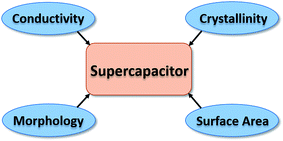
The electrochemical performance of an electrode depends on the structure of the material, which should support fast kinetics of ionic and electronic mobility (Fig. 1). A highly crystalline active material has efficient electronic conductivity and cycling capability.44 In the case of nickel hydroxide synthesized in the presence of aluminum compounds, the crystallinity of the sample increases when treated for 1 h at 140 °C under hydrothermal conditions. The enhancement in crystallinity of the sample increased the electrode's discharge capability.2.2. Morphology
The morphology of the electroactive material on the current collector is an important determinant of the electrochemical properties of the material. Different types of morphologies evolve during layered double hydroxide (LDH) synthesis, such as nanorods, nanosheets, and nanospheres. Chen et al. reported that electrochemical performance increased with an increase in size of CoNi(OH)2 nanosheets, and the growth is composition dependent (Fig. 2).45 Sun et al. evaluated the effect of mixed nickel and cobalt hydroxide materials on morphology evolution of nanosheet, nanoplate–nanosphere, nanorod, and nanoparticle morphologies (Fig. 3).46 Among different morphologies observed, the nanosheets exhibit the best electrochemical performance. Zhu et al. synthesized nickel cobalt bimetallic hydroxide with a nanowire nanoplatelet (NWNP) morphology that showed good electrochemical performance (Fig. 4).47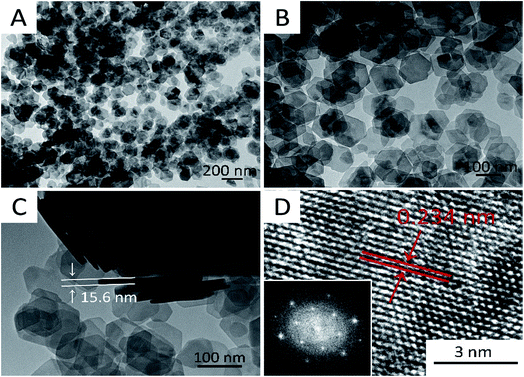 | ||
| Fig. 2 Typical TEM images of the as-prepared Co0.2Ni0.8(OH)2 hexagonal nanosheets at (A) low; (B) middle; (C) high magnification; and (D) HRTEM image. The inset in (D) is the FFT image of the selected area. Reproduced from ref. 45, with permission of Elsevier. | ||
 | ||
Fig. 3 SEM images showing the morphology evolution from nanosheets, nanorods to nanoparticles at Ni![[thin space (1/6-em)]](https://www.rsc.org/images/entities/char_2009.gif) : :![[thin space (1/6-em)]](https://www.rsc.org/images/entities/char_2009.gif) Co ratios: (a) 1 Co ratios: (a) 1![[thin space (1/6-em)]](https://www.rsc.org/images/entities/char_2009.gif) : :![[thin space (1/6-em)]](https://www.rsc.org/images/entities/char_2009.gif) 0, (b) 1 0, (b) 1![[thin space (1/6-em)]](https://www.rsc.org/images/entities/char_2009.gif) : :![[thin space (1/6-em)]](https://www.rsc.org/images/entities/char_2009.gif) 4, and (c) 0 4, and (c) 0![[thin space (1/6-em)]](https://www.rsc.org/images/entities/char_2009.gif) : :![[thin space (1/6-em)]](https://www.rsc.org/images/entities/char_2009.gif) 1. Reproduced from ref. 46, with permission of Elsevier. 1. Reproduced from ref. 46, with permission of Elsevier. | ||
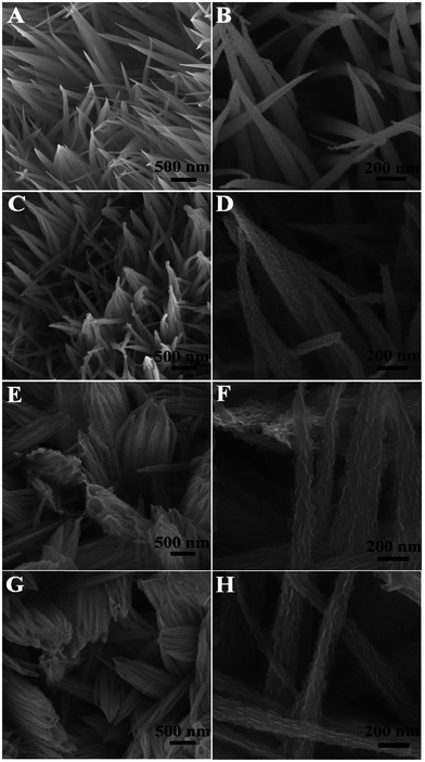 | ||
| Fig. 4 Low and high magnification SEM images of the nanostructure arrays obtained at different immersion times: (A) and (B) NWA; (C) and (D) NWPA-6 h; (E) and (F) NWPA-12 h; (G) and (H) NWPA-18 h. Reproduced from ref. 47, with permission of The Royal Society of Chemistry. | ||
2.3. Surface area
The surface area of the active mass contributes to the electrochemical capacitance of the electrode. Enhancement of the surface area leads to the presence of more active sites, allowing better ionic diffusion and hopping of electrons from the active mass to the current collector. CoNi0.5LDH prepared in situ has a surface area of 212.5 m2 g−1, which decreased to 136 m2 g−1 when the sample is prepared ex situ, and higher electrochemical performance is observed for the electrode with the greater surface area (Fig. 5).48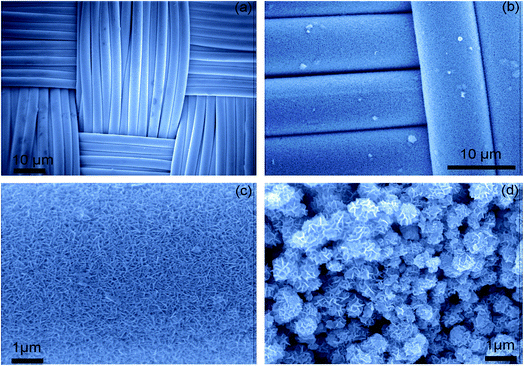 | ||
| Fig. 5 (a) FE-SEM images of (a) carbon cloth (CC), (b and c) conformally coated CoNi0.5LDH nanoflakes and (d) non-conformally coated CoNi0.5LDH nanoflakes. Reproduced from ref. 48, with permission of Elsevier. | ||
2.4. Conductivity
The conductivity of the active material is very important, as it aids in fast electron mobility. The conductivity of cobalt hydroxide is greater than that of nickel hydroxide. Mixtures of hydroxides of nickel and cobalt show better supercapacitive behaviour than either hydroxide type alone. To further enhance conductivity, these hydroxides can be mixed with conducting carbon materials, which can increase the rate and supercapacitive properties drastically. Conductivity can be a more important criterion than the surface area for enhancing the performance (Fig. 6).49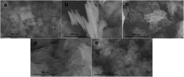 | ||
| Fig. 6 SEM images of (a) Ni0.74Co0.26(OH)2, (b) Ni0.65Co0.35(OH)2, (c) Ni0.47Co0.53(OH)2, (d) Ni0.34Co0.66(OH)2, and (e) Ni0.28Co0.72(OH)2, respectively. Reproduced from ref. 49, with permission of Elsevier. | ||
2.5. Energy storage mechanism
NiCo LDHs follow the redox reactions in the electrochemical storage process which is mentioned as follows.| Co(OH)2 + OH− ↔ CoOOH + H2O + e− | (1) |
| Ni(OH)2 + OH− ↔ NiOOH + H2O + e− | (2) |
Hu et al. reported that binary hydrous Co–Ni oxides are more suitable for electrochemical supercapacitors than for rechargeable batteries50 which is less supported by some of the recent reports.51,52 But the majority of the reports and reviews mention about the supercapacitor nature of NiCo LDH.1,53–60
3. Electrode fabrication
Electrodes can be fabricated either by a one- or two-step process. Active materials can be deposited onto substrates by simple one-step processes involving hydrothermal, electrodeposition, or chemical bath deposition techniques. In two-step processes, the active material is first prepared by precipitation or a hydrothermal process and then deposited onto the substrate by using a binder.3.1. Electrodes with binders
Active materials prepared in the first step by different synthesis routes are mixed with conducting carbon black, a polymeric binder, and solvent at a certain ratio to obtain a slurry. This slurry is deposited on the substrate by drop casting or doctor blading to prepare the electrode. Pristine nickel cobalt hydroxide is prepared by hydrothermal or precipitation processes. NiCo LDH was grown on graphene oxide (GO) or carbon nanotubes (CNTs) to prepare composite material.3.1.1.1. Hydrothermal deposition. The hydrothermal process is one of the simple, one-step processes to prepare the active materials at mild temperatures. The generation of α-phase NiCo hydroxide requires stringent conditions; however, in the presence of N-methylpyrrolidone (NMP), the α-phase can be generated in one simple step.61 An interconnected nanosheet morphology is advantageous for redox electrochemical reactions. The Ni0.67Co0.33 LDH electrode has a specific capacitance of 1337.4 F g−1 at a current density of 1 A g−1 and 60.9% capacitance retention at a very high current density of 50 A g−1. Enhancement of the cobalt ratio in the NiCo hydroxide does not enhance the specific capacitive behavior further, indicating that cobalt does not contribute much to the capacitive behavior. The better performance of the NiCo hydroxide electrode is due to its poorly crystallized state of the α-phase bimetallic hydroxide. This electrode has higher electrochemical activity; ultrathin nanosheets of bimetallic hydroxide have a higher surface area and better contact between the electrode and electrolytic ions than the monometallic electrodes, resulting in better capacitance performance. The optimized feed ratio of nickel to cobalt in terms of maximum contribution from both components was found to be 4
![[thin space (1/6-em)]](https://www.rsc.org/images/entities/char_2009.gif) :
:![[thin space (1/6-em)]](https://www.rsc.org/images/entities/char_2009.gif) 2. NiCo hydroxide in the α-phase is synthesized in ethylene glycol solvent, and the structure was maintained even for different compositions of nickel and cobalt.62 The Ni0.5Co0.5(OH)2 electrode is seen to have interconnected micrometer-sized particles. Numerous nanosheets were present, and the electrode had a specific capacitance of 1600 F g−1 at a current density of 1 A g−1. Compared to other α-phase monometallic hydroxides such as nickel hydroxide63 and cobalt hydroxide,64 composites of nickel hydroxide/r-GO65 showed better performance. The performance of nickel hydroxide/rGO composites is much better than those of NiCo bimetallic hydroxides,46,66 NiCo oxides,67–71 and NiAl hydroxides.72,73 The capacitance retention is 60.16% at a current density of 50 A g−1, which is much higher than that of the monometallic nickel hydroxide (28%). Diffusion kinetics of ions and electrons determine the rate capability, as a result, the path of mobility is also important. Cobalt ions are oxidized to cobalt perhydroxide ions, which are more conducting in nature and enhance electron transfer during the electrochemical reaction. This is one of the reasons why bimetallic hydroxides have a higher rate capability than monometallic hydroxide electrodes. The bimetallic metal hydroxide shows a cycling stability of 100% after 1000 charge–discharge cycles at a current density of 10 A g−1. In the case of monometallic α-phase nickel hydroxide electrodes, transformation into the β-phase during charge–discharge cycling results in a decline of the specific capacitance of the material.
2. NiCo hydroxide in the α-phase is synthesized in ethylene glycol solvent, and the structure was maintained even for different compositions of nickel and cobalt.62 The Ni0.5Co0.5(OH)2 electrode is seen to have interconnected micrometer-sized particles. Numerous nanosheets were present, and the electrode had a specific capacitance of 1600 F g−1 at a current density of 1 A g−1. Compared to other α-phase monometallic hydroxides such as nickel hydroxide63 and cobalt hydroxide,64 composites of nickel hydroxide/r-GO65 showed better performance. The performance of nickel hydroxide/rGO composites is much better than those of NiCo bimetallic hydroxides,46,66 NiCo oxides,67–71 and NiAl hydroxides.72,73 The capacitance retention is 60.16% at a current density of 50 A g−1, which is much higher than that of the monometallic nickel hydroxide (28%). Diffusion kinetics of ions and electrons determine the rate capability, as a result, the path of mobility is also important. Cobalt ions are oxidized to cobalt perhydroxide ions, which are more conducting in nature and enhance electron transfer during the electrochemical reaction. This is one of the reasons why bimetallic hydroxides have a higher rate capability than monometallic hydroxide electrodes. The bimetallic metal hydroxide shows a cycling stability of 100% after 1000 charge–discharge cycles at a current density of 10 A g−1. In the case of monometallic α-phase nickel hydroxide electrodes, transformation into the β-phase during charge–discharge cycling results in a decline of the specific capacitance of the material.
However, in the bimetallic hydroxide, the interlayer space is occupied by ethylene glycol, which inhibits the transformation of the α-phase into the β-phase. The absence of ethylene glycol from the interlayer of the monometallic hydroxide results in easy transformation into the β-phase because of which fast deterioration of the cycling stability occurs. The effect of hydrolyzing agents like urea, KOH, and Na2CO3, in the presence of ethylene glycol has been investigated.49 The use of urea leads to the formation of a flower-like morphology, and the presence of ethylene glycol increases the size of the nanoflowers to more than 500 nm. Complexation between metal ions and ammonia as well as high temperature and pressure conditions in an autoclave has been shown to enhance the solubility of the metal hydroxide, resulting in the formation of large metal hydroxide nanoflakes. When the ratio of nickel to cobalt approaches 1![[thin space (1/6-em)]](https://www.rsc.org/images/entities/char_2009.gif) :
:![[thin space (1/6-em)]](https://www.rsc.org/images/entities/char_2009.gif) 1, dissolution–recrystallization of the metal hydroxide becomes easier, leading to the formation of larger nanoflakes and nanoflowers. Crystallization occurs in the mixed α- and β-phase. Ni0.74Co0.26(OH)2 and Ni0.28Co0.72(OH)2 show the highest surface areas of 162.3 and 122.7 m2 g−1, respectively. The Ni0.28Co0.72(OH)2 electrode has a specific capacitance of 206.7 F g−1 at a scan rate of 1 mV s−1 due to the high electrical conductivity of cobalt, although the surface area is less than that of the Ni0.74Co0.26(OH)2 electrode.
1, dissolution–recrystallization of the metal hydroxide becomes easier, leading to the formation of larger nanoflakes and nanoflowers. Crystallization occurs in the mixed α- and β-phase. Ni0.74Co0.26(OH)2 and Ni0.28Co0.72(OH)2 show the highest surface areas of 162.3 and 122.7 m2 g−1, respectively. The Ni0.28Co0.72(OH)2 electrode has a specific capacitance of 206.7 F g−1 at a scan rate of 1 mV s−1 due to the high electrical conductivity of cobalt, although the surface area is less than that of the Ni0.74Co0.26(OH)2 electrode.
The effect of the surfactant cetyltrimethylammonium bromide (CTAB) on the morphology of NiCo hydroxide has also been studied.74 Addition of CTAB results in the formation of hexagonal nanoplates with smooth surfaces. In the absence of CTAB, the scobinate hexagonal nanoplates have greater surface roughness. Scobinate hexagonal nanoplates have a specific capacitance of 294.32 F g−1 at a current density of 1 A g−1, while that of the smooth nanoplates is 127 F g−1 under the same conditions. This difference is because of the higher surface area of scobinate hexagonal nanoplates (19.32 m2 g−1) than that of smooth nanoplates (12.36 m2 g−1).
The morphologies of NiCo LDHs change with the nickel and cobalt composition, which in turn dictates the electrochemical performance.45 CoNi LDHs crystallize in a hexagonal nanosheet morphology. An increase in the concentration of nickel in LDH composition reduces the size of nanosheets. Co(OH)2, Co0.8Ni0.2(OH)2, Co0.5Ni0.5(OH)2, Co0.2Ni0.8(OH)2, and Ni(OH)2 nanosheets have 1 μm, 400 nm, 200 nm, 100–150 nm, and 160 nm diameters respectively. However, the d-spacing of the (101) lattice plane increases as the cobalt ratio increases in the mixed NiCo hydroxide. The Co0.2Ni0.8(OH)2 electrode has the highest specific capacitance of 1840 F g−1 at a current density of 1 A g−1. The specific capacitance of the electrode is reduced to 1240 F g−1 when the current density increases from 1 to 4 A g−1, which corresponds to a capacitance retention of 67.39%.
Carbonate and nitrate anions intercalated in NiCo LDHs with different nickel and cobalt compositions result in an enhanced interlayer spacing of 9.22 Å.75 The resulting material has a 3D flower morphology comprising nanosheets with a thickness of 30–40 nm. The electrode with high active material loading (6 mg cm−2) has a specific capacitance of 1803 F g−1 at a current density of 1 A g−1 and 40% capacitance retention when the current density is increased to 10 A g−1. For Co7Ni3(OH)2, the capacitance retention is 61.9% under similar conditions, indicating that the higher the cobalt percentage is, the better the rate capability is. However, the electrode with the maximum nickel ratio has the highest capacitance, which might be due to charge hopping between nickel and cobalt ions. The binary hydroxide has binary couples of Co2+/Co3+ and Ni2+/Ni3+ that participate in redox reactions, resulting in better electronic conductivity, which is added by a large surface area of the 3D structure.
Ni(OH)2–Co(OH)2 with a 2![[thin space (1/6-em)]](https://www.rsc.org/images/entities/char_2009.gif) :
:![[thin space (1/6-em)]](https://www.rsc.org/images/entities/char_2009.gif) 1 molar ratio has an urchin-like hollow microsphere morphology with a diameter of 1.5 μm and needle-like nanorods of 400 nm in length and 20 nm in width (Fig. 7).76 This material crystallizes in a mixed α- and β-phase and has a specific capacitance of 2164 F g−1 at a current density of 1 A g−1 due to its BET surface area of 134 m2 g−1.55 It showed good cycling stability of 56.4% capacitance retention after 500 cycles at 20 A g−1. The Ni(OH)2@Co(OH)2 core–shell structure has a nanohexagon morphology and could be tuned by varying the temperature and concentration of hydrazine monohydrate.77 The material has a specific capacitance of 396 F g−1 at a current density of 0.3 A g−1 due to its high surface area of 23.3 m2 g−1. It shows good cycling stability with 95% capacitance retention after 2500 cycles at a current density of 1 A g−1.
1 molar ratio has an urchin-like hollow microsphere morphology with a diameter of 1.5 μm and needle-like nanorods of 400 nm in length and 20 nm in width (Fig. 7).76 This material crystallizes in a mixed α- and β-phase and has a specific capacitance of 2164 F g−1 at a current density of 1 A g−1 due to its BET surface area of 134 m2 g−1.55 It showed good cycling stability of 56.4% capacitance retention after 500 cycles at 20 A g−1. The Ni(OH)2@Co(OH)2 core–shell structure has a nanohexagon morphology and could be tuned by varying the temperature and concentration of hydrazine monohydrate.77 The material has a specific capacitance of 396 F g−1 at a current density of 0.3 A g−1 due to its high surface area of 23.3 m2 g−1. It shows good cycling stability with 95% capacitance retention after 2500 cycles at a current density of 1 A g−1.
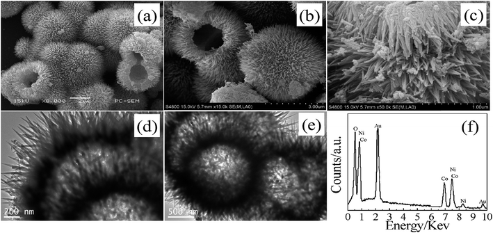 | ||
| Fig. 7 SEM (a), FESEM (b) and (c), TEM (d) and (e) images, and EDS (f) pattern of the Ni(OH)2–Co(OH)2 composite. | ||
Nickel hydroxide crystallized in the α-phase was deposited with cobalt hydroxide, which did not change the phase.78 This material has a specific capacitance of 2193 F g−1 at a current density of 2 A g−1 with a good capacitance retention of 63.33% when the current density is increased to 20 A g−1. Nickel hydroxide under similar conditions has 45.7% capacitance retention and good cycling stability with 69.1% capacitance retention after 1000 cycles at a current density of 5 A g−1. These studies revealed that, whether hydroxides of nickel and cobalt are in LDH form or trace of one present in other hydroxide, they act in tandem, which enhances the electrochemical performance of an electrode.
3.1.1.2. Precipitation. A precipitation method is a simple and cost-effective method that can be performed at lower temperatures with minimal energy input. The presence of ethylene glycol leads to intercalated NiCo LDH that crystallizes in the α-phase.53 The general formula of the LDH is [M2+M2+(OH)2][Az−]·mH2O, where Az− is the charge compensation inorganic or organic anion and M is Ni2+ or Co2+. The intercalated LDH has a (003) interlamellar distance of 9.64 Å, which is higher than that of the LDH without intercalation (7.9 Å). The electronegative hydroxyl group of the EG interacts with the Co/Ni LDH and bonded chemically. The thickness of the EG Co/Ni LDH nanosheets is around 5 nm with poor crystallinity. The BET surface area of EG Co/Ni LDH is 168 m2 g−1, while without intercalation, it is 60 m2 g−1. The specific capacitance of the EG Co/Ni LDH electrode is 4160 F g−1 at a current density of 1 A g−1 with a capacitance retention of 31.5% at a current density of 50 A g−1. The electrode has good cycling stability with a capacitance retention of 96% after 100 cycles at a current density of 1 A g−1. LDH without EG intercalation has a specific capacitance of 3020 F g−1 at a current density of 1 A g−1. Its cycling stability is 72%, which is much lower than that of the EG Co/Ni LDH due to the lower gallery space (Fig. 2). When the loading mass of the electrode is increased, the specific capacitance decreases to 774 F g−1 at a current density of 0.2 A g−1.79 The cycling stability of the electrode measured after 500 charge discharge cycles is 75% at a current density of 1 A g−1.
When polyvinyl pyrrolidone (PVP) is used instead of EG in the solution for precipitation of NiCo LDH, the binary hydroxide crystallizes in the α-phase with a porous structure, and the diameters of nanoparticles ranged from 10 to 30 nm.80 The electrode prepared with 3 mg cm−2 mass loading has a BET surface area of 109.8 m2 g−1 with a porosity of 1.5–5 nm; it was easy for solvated ions with diameters of 0.6–0.76 nm to penetrate the inter-gallery spacing. The electrode has a specific capacitance of 2614 F g−1 at a current density of 1 A g−1 with a capacity retention of 85.9%, even at 10 A g−1. The percentage of cobalt between 0.570% and 0.443% gave the optimum capacitance.
Epoxide propylene was used to prepare a NiCo LDH with ammonium persulfate as a hydrolyzing agent.81 This crystallizes in a hydrotalcite-like structure. Sulfate group intercalation in the LDH structure increased the inter-gallery spacing and the material has a nanosheet-like morphology. The specific capacitance of the electrode made up of this material is 2548 F g−1 at a current density of 0.9 A g−1, and it showed a good capacitance retention of 76.9% at a current density of 23.2 A g−1.
NiCo LDHs synthesized by varying the composition ratio, reaction time, and pH of the reactant crystallize in microsphere form with an average size of 2.5 μm. A three-dimensional flower with a hierarchical architecture comprising numerous interconnected nanosheets is observed (Fig. 8).82 Reproducing LDH morphologies is always very difficult when scaling up synthesis; in this case, it remained intact during the scaling-up process. LDH crystallizes in the hydrotalcite α-Ni(OH)2 phase. The strongest (003) diffraction peak is very high and narrow, indicating good crystallinity, with a d-spacing value of 0.89 nm, which is higher than those of α-Ni(OH)2 (0.72 nm) and α-Co(OH)2 (0.46 nm). Intercalation of inorganic anions, such as CO32−, NO3−, and OH−, which functions as electroactive species in the redox reaction, enhanced the d-spacing. The material has a BET surface area of 70.78 m2 g−1, and the effect of the cobalt concentration on the morphology of the NiCo LDH was studied in detail. In the absence of cobalt, the thickness of the nanosheets in the nanoflowers is 50 nm; this decreased to 30 nm as the Ni![[thin space (1/6-em)]](https://www.rsc.org/images/entities/char_2009.gif) :
:![[thin space (1/6-em)]](https://www.rsc.org/images/entities/char_2009.gif) Co ratio was increased to 4
Co ratio was increased to 4![[thin space (1/6-em)]](https://www.rsc.org/images/entities/char_2009.gif) :
:![[thin space (1/6-em)]](https://www.rsc.org/images/entities/char_2009.gif) 6. NiCo LDH with this higher cobalt ratio has a more uniform and porous structure because of the transformation of the crystal structure from β-Ni(OH)2 into the hydrotalcite phase. A further increase in the cobalt ratio (2
6. NiCo LDH with this higher cobalt ratio has a more uniform and porous structure because of the transformation of the crystal structure from β-Ni(OH)2 into the hydrotalcite phase. A further increase in the cobalt ratio (2![[thin space (1/6-em)]](https://www.rsc.org/images/entities/char_2009.gif) :
:![[thin space (1/6-em)]](https://www.rsc.org/images/entities/char_2009.gif) 8, Ni/Co) resulted in structural collapse because of the poor crystallinity of Co(OH)2. The optimized reaction time and pH are 15 h and 8.72, respectively. Electrodes prepared with 5–8 mg cm−2 of active materials show a specific capacitance of 2228 F g−1 at 1 A g−1, with 32% capacitance retention.
8, Ni/Co) resulted in structural collapse because of the poor crystallinity of Co(OH)2. The optimized reaction time and pH are 15 h and 8.72, respectively. Electrodes prepared with 5–8 mg cm−2 of active materials show a specific capacitance of 2228 F g−1 at 1 A g−1, with 32% capacitance retention.
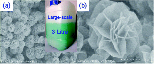 | ||
| Fig. 8 (a) Typical and (b) partial SEM images of LDH nanosheets based on 3D flower-like hierarchical Ni/Co-LDH microspheres; the inset part in (a) displays the actual sight of a large-scale preparation strategy of the Ni/Co-LDH microsphere material. Reproduced from ref. 82, with the permission of American Chemical Society. | ||
3.1.2.1. Hydrothermal. NiCo-LDH/r-GO composites are prepared in the presence of CTAB surfactants, allowing LDH to coat r-GO uniformly without any agglomeration.83 The nanocomposite has a higher surface area (27.4 m2 g−1) than the pristine LDH (7.5 m2 g−1). The composite electrode has a specific capacitance of 1911.1 F g−1 at a current density of 2 A g−1 along with a capacitance retention of 55.7% when the current density increases to 20 A g−1. Pristine LDH has a very low supercapacitance of 342.9 F g−1 at a scan rate of 20 mV s−1. Enhancement of the electrochemical performance of the composite electrode occurred because r-GO itself has some specific capacitance and the higher conductivity of r-GO enhanced redox reactions by facilitating fast electron and ion transfer. Furthermore, a r-GO effective matrix for the growth of LDH nanosheets prevented the agglomeration of the LDH, which is good for ionic mobility. The composite electrode has good cycling behavior, with 74% capacitance retention after 1000 cycles at a current density of 20 A g−1, while the pristine LDH has a capacitance retention of only 51% under the same conditions.
The composite of LDH and r-GO prepared in the presence of L-ascorbic acid (LAA) resulted in crystallization in the β-phase.84 The presence of LAA lowers the agglomeration of exfoliated r-GO, which enhances the mobility of the electrolyte ions. The NiCo–OH/r-GO electrode has a specific capacitance of 1691 F g−1 at a current density of 0.5 A g−1, with a capacitance retention of 82.6% when the current density is increased to 10 A g−1. The capacitance retention after 1000 charge–discharge cycles was 100% for NiCo–OH/r-GO electrodes, indicating good conductivity. This is attributed to the intimate contact between NiCo–OH and r-GO, which provided good electron mobility, as well as the large interface between the metal hydroxide and r-GO. The CoNi(OH)2/r-GO composite was prepared in the presence of ammonium hydroxide (hydrolyzing agent) and hydrazine.85 A high mass loaded (4.5–5.5 mg cm−2) electrode has a specific capacitance of 1294 F g−1 at a current density of 0.5 A g−1 with a good rate capacitance of 68.8% at a current density of 2 A g−1. When the hydrothermal reaction time increases from 10 to 12 h, the rate capability of the resulting electrode increased to 76% because of the higher crystallinity of the active material. However, specific capacitance decreased with the enhancement of crystallinity. This indicates a trade-off between crystallinity, rate capability, and specific capacitance, indicating that it would be difficult to enhance both specific capacitance and rate capability simultaneously.
3.1.2.2. Precipitation. The NiCo hydroxide/r-GO composite was prepared in the presence of potassium ferrocynate and hydrazine hydrate which formed a nanosheet-like morphology.86 The BET surface area of the composite is 240 m2 g−1, compared to 204 m2 g−1 for pristine LDH. The composite electrode has a specific capacitance of 835 F g−1 at a current density of 1 A g−1, with a capacitance retention of 49.1% at a current density of 5 A g−1. It displayed 92% capacitance retention after 5000 cycles at a current density of 5 A g−1. The NiCo LDH/graphene composite has a 3D flower cluster morphology with interconnected nanoflakes of 8 nm in thickness.87 The basal spacing for the pure LDH is 0.72 nm, which increases to 0.86 nm for the composite, which crystallizes in the α-phase. The composite intercalated with CO32−, NO3−, or CN− anions has a BET surface area of 408.5 m2 g−1. The specific capacitance of the composite electrode is 1980.7 F g−1 at a current density of 1 A g−1 and it showed a good capacitance retention of 92.6% at a current density of 4 A g−1. The cycling stability of the composite is much better than that of the pristine LDH.
The NiCo LDH/CNT composite with 16–17% CNTs has a hydrotalcite-like structure with an enlarged d-spacing of 9.5 Å due to the intercalation of CO32− and SO42− anions in the crystalline lattice.88 Composite nickel cobalt LDH with a 1![[thin space (1/6-em)]](https://www.rsc.org/images/entities/char_2009.gif) :
:![[thin space (1/6-em)]](https://www.rsc.org/images/entities/char_2009.gif) 2 molar ratio of nickel
2 molar ratio of nickel![[thin space (1/6-em)]](https://www.rsc.org/images/entities/char_2009.gif) :
:![[thin space (1/6-em)]](https://www.rsc.org/images/entities/char_2009.gif) cobalt has a specific capacitance of 1151 F g−1 at a current density of 1 A g−1 with a good capacitance retention of 61% at a very high current density of 70 A g−1. The electrode has 77% capacitance retention after 10
cobalt has a specific capacitance of 1151 F g−1 at a current density of 1 A g−1 with a good capacitance retention of 61% at a very high current density of 70 A g−1. The electrode has 77% capacitance retention after 10![[thin space (1/6-em)]](https://www.rsc.org/images/entities/char_2009.gif) 000 cycles at a current density of 10 A g−1. This might be due to the generation of conducting CoOOH during the charge–discharge process, which increases the overall performance of the electrode. Intercalated SO42− ions enhance the interlayer spacing as well as the conductivity. CNTs enhance the electron mobility and reduce the electrochemical polarization. The presence of the carbon material in the composite LDH electrode enhances electronic conductivity, which results in good capacitance retention and enhances the cycling life of the electrode.
000 cycles at a current density of 10 A g−1. This might be due to the generation of conducting CoOOH during the charge–discharge process, which increases the overall performance of the electrode. Intercalated SO42− ions enhance the interlayer spacing as well as the conductivity. CNTs enhance the electron mobility and reduce the electrochemical polarization. The presence of the carbon material in the composite LDH electrode enhances electronic conductivity, which results in good capacitance retention and enhances the cycling life of the electrode.
3.2. In situ growth of active materials
Here, we discuss electrodes prepared with binders. Binders in active materials act as dead volume and affect the electrochemical performance of the electrode. In the case of in situ growth, the contact between the active material and current collector is considerably improved, leading to better electrochemical performance. To remove the binder, the active material is grown directly on the substrate by a hydrothermal, precipitation, chemical bath deposition, or electrochemical deposition method. This section is divided according to the method of deposition of the active material on the substrate.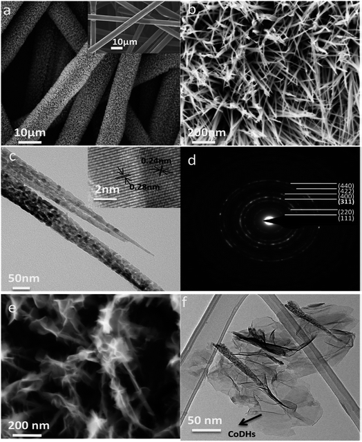 | ||
| Fig. 9 (a) SEM image of CFP before (inset) and after the growth of NiCo2O4 nanowires. (b) High-magnification SEM image of NiCo2O4 nanowires grown on CFP. (c) TEM image and HRTEM image (inset) of 2 NiCo2O4 nanowires. (d) Diffraction pattern of a NiCo2O4 nanowire. (e) SEM image of a CoDH coating on NiCo2O4 nanowires grown on CFP. (f) TEM image of CoDHs/NiCo2O4 nanowires grown on CFP. Reproduced from ref. 9, with the permission of American Chemical Society. | ||
NiCo LDHs were deposited on zinc oxide nanoflake (ZnONF) and zinc oxide nanowire (ZnONW) current collectors.92 The porosity of ZnONF was around 25 m2 g−1 which is about 12 times higher than that of ZnONW (1.75 m2 g−1). When the scan rate is increased from 20 to 100 mV s−1, the shape of the redox peak remains intact, indicating the good electronic conductivity of the current collector. The specific capacitance of the nanoflake structure is 1624 F g−1 at a current density of 10 A g−1 which is about 1.6 times higher than the specific capacitance of the nanowire structure and 5 times higher than that of the pristine NiCo LDH. The electrode has a capacitance retention of 71.4% when the current density is increased to 100 A g−1. A nanoflake structure shows good cycling behavior, with 94% capacitance retention after 2000 cycles at a current density of 40 A g−1. The better performance of the nanoflake structure than the nanowire is due to the higher surface area and lower internal resistance. In situ-grown structures show better performance than the electrode prepared with the use of binders.
NiCo LDH nanoflakes were deposited on a NiCo2S4 (NCS) current collector with a nanorod morphology by electrodeposition.93 This electrode has a high capacity of 2.31 C cm−2 at a current density of 0.5 mA cm−2 and a good capacitance retention of 69.9% when the current density is increased to 20 mA cm−2. The electrode has an excellent cycling stability of 78% after 4000 cycles at a scan rate of 50 mV s−1. The advantage of the core–shell structure is an increase in electron mobility at the electrode and plenty of space for deposition of the shell material. Core–shell electrodes made using NiCo LDHs show good electric conductivity, high specific surface area, suitable mesoporosity, and a good electrochemical response.
NiCo LDH prepared in the presence of CTAB as a surfactant crystallizes in the hydrotalcite phase with a nanoplate-array-like morphology.94 The pH of the medium dictates the size of the nanoplates, below 5.5 pH, the thickness of the nanoplate is less than 500 nm and above 5.5 pH the thickness is 500 nm. At the optimized pH of 5.5, the porosity of the sample is 3–5 nm with a BET surface area of 92.4 m2 g−1. The material has the best specific capacity of 178.8 mA h g−1 at a current density of 10 A g−1 with a capacitance retention of 63.78% at a very high current density of 40 A g−1. NiCo LDH that was deposited in the presence of CTAB as a surfactant has an ultrathin-sheet-like morphology and a BET surface area of 84.7 m2 g−1.95 The electrode exhibits good electrochemical performance with a specific capacitance of 2654.9 F g−1 at a current density of 1 A g−1 and a good capacitance retention of 33.69% when the current density is increased to 20 A g−1. It showed 77% capacitance retention after 1500 cycles at a current density of 10 A g−1. NiCo LDH was prepared in the presence of hexamethylenetetramine (HMTA) as a hydrolyzing agent.96 It has a specific capacitance of 1734 F g−1 at a current density of 6 A g−1 and a capacitance retention of 66.1% when the current density is increased to 30 A g−1, which are higher than those reported by Salunkhe et al.97
Zheng et al. prepared a NiCo LDH on a nickel sheet; a nickel/cobalt ratio of 1![[thin space (1/6-em)]](https://www.rsc.org/images/entities/char_2009.gif) :
:![[thin space (1/6-em)]](https://www.rsc.org/images/entities/char_2009.gif) 2 yielded the optimum performance.98 Porous LDH nanosheets are aligned vertically on the nickel sheet. The resulting electrode has a specific capacitance of 2184 F g−1 at a current density of 1 A g−1 with a good capacitance retention of 68.4% when the current density is increased to 20 A g−1. It too showed good cycling performance (88.5% capacity retention after 2000 cycles at a current density of 1 A g−1).
2 yielded the optimum performance.98 Porous LDH nanosheets are aligned vertically on the nickel sheet. The resulting electrode has a specific capacitance of 2184 F g−1 at a current density of 1 A g−1 with a good capacitance retention of 68.4% when the current density is increased to 20 A g−1. It too showed good cycling performance (88.5% capacity retention after 2000 cycles at a current density of 1 A g−1).
Ni0.5Co1.5(OH)2CO3 nanowires prepared on a nickel foam substrate and converted to Ni0.5Co1.5(OH)2 by dipping in an alkaline solution for extended period exhibited a nanowire nanoplate (NWNP) morphology and a brucite crystal structure in the β-phase.47 The obtained material has a BET surface area of 24.97 m2 g−1 and a specific capacitance of 928.4 F g−1 at a current density of 5 mA cm−2, as well as good capacity retention (81.1%) when the current density is increased to 50 mA cm−2. The electrode showed 82–85% capacitance retention after 1000 cycles at a current density of 30 mA cm−2. The unusual penetration depth of the electrode is 20 nm, and its thickness is around 10 nm, which is sufficient for full penetration.
NiCo LDH was deposited onto carbon fabric in situ and its properties were compared with the same material prepared ex situ.48 The in situ structure has a nanoflake morphology with a surface area of 212.5 m2 g−1 and a porosity of 3 nm, whereas the ex situ prepared material has a surface area of 136 m2 g−1. The nanoflake material has a specific capacitance of 1938 F g−1 at a current density of 1 A g−1 and a capacity retention of 80% at 50 A g−1 and a good capacitance retention of 95.4% after 3000 cycles at 20 A g−1. The ex situ electrode has a specific capacitance of 1292 F g−1 and lower capacitance retention and cycling stability than the in situ electrode. In other words, the in situ grown electrode shows better electrochemical performance than the electrode prepared with the use of a binder.
Titanium nitride nanotubes (TiN NTA) with length of 100–120 nm were electrodeposited with a NiCo LDH that has a nanosheet-like rippled silk morphology.54 The resulting material has a specific capacitance of 2543 F g−1 at a scan rate of 5 mV s−1 and showed 26% capacitance retention when the scan rate is increased to 500 mV s−1. The electrode showed excellent cycling stability (95.75% capacitance retention after 5000 cycles at a scan rate of 100 mV s−1 in CV tests).
CNTs were grown on a nickel foam substrate and electrodeposited with a NiCo LDH. Both Ni(OH)2 and Co(OH)2 crystallize in the rhombohedral phases, with bands appearing in the (003), (100), and (001) planes.102 An electrode prepared with an active mass of 0.9 mg cm−2 has a specific capacitance of 2170 F g−1 at 1 mA cm−2 and 80.9% capacitance retention when the scan rate is increased to 20 mA cm−2. It has 61.5% retention after 5000 charge discharge cycles at a scan rate of 20 mA cm−2. An electrode without CNTs has a three-fold lower BET surface area than the electrode with CNTs, and the former has a specific capacitance of 1136 F g−1 at a current density of 1 A g−1 with a capacitance retention of 55.9% when the current density is increased to 20 A g−1. Density functional theory (DFT) calculations revealed that Ni(OH)2 shows semiconductor behavior with a band gap of 3.43 eV; this gap reduced to 3.06 eV for Ni0.5Co0.5(OH)2 with an increase in the cobalt concentration, resulting in a better energy storage device.
Another group grew CNTs on nickel foam and electrodeposited NiCo LDH with CNT diameters of 20–250 nm, a length of 10 μm, and density around 16 mg cm−2 (Fig. 10).103 The sp2 carbons of the CNTs resulted in the sp2-C–Ni covalent bond formation, and hence better interaction between the CNTs and the nickel foam. Advantages of this current collector are its high intrinsic electrical conductivity, strong interfacial adhesion, and large specific surface area. It functioned as a good template for the preparation of 3D hierarchical core–shell structures of NiCo LDH@CNT with a thickness around 27 nm. An electrode with an active mass of 8.5 mg cm−2 has a specific capacitance of 2046 F g−1 at a current density of 1 A g−1 with 65.2% capacitance retention when the current density is increased to 15 A g−1. The NiCo LDH electrode without CNTs exhibits similar behavior when the mass loading is 0.54 mg cm−2; when the mass loading is increased to 2.29 mg cm−2, electrochemical performance is reduced to less than half of the original performance. This indicates that the presence of CNTs supports good performance, even with higher mass loading.
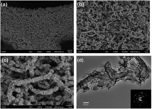 | ||
| Fig. 10 (a) Over-view, (b and c) high magnification FESEM images of the NiCo-LDH@CNT electrode and (d) HRTEM image of the NiCo-LDH@CNT core–shell structure. The inset (d) is the corresponding SAED pattern taken from NiCo-LDH nanoflakes. Reproduced from ref. 105, with permission of The Royal Society of Chemistry. | ||
NiCo LDH electrodeposited onto nickel foam and annealed at a high temperature for conversion to oxide was used to prepare LDH@NiCo2O4 electrodes.104 In the NiCo2O4@NiCo(OH)2 core–shell nanostructure, mesoporous NiCo2O4 nanosheets with good electrical conductivity provided electron superhighways for charge storage and delivery. The open spaces in this structure can act as ion reservoirs to reduce the diffusion length, resulting in a reduction in transport resistance. Enhancement of intercalation/deintercalation of ions in turn enhanced the utility of the active mass. The NiCo2O4@Co0.33Ni0.67(OH)2 electrode prepared with an active mass of 5.5 mg cm−2 has a specific capacitance of 1045 F g−1 at a current density of 1 A g−1, which is about three times higher than the pristine nickel cobalt oxide. The electrode showed a capacitance retention of 83.7% when the current density is increased to 50 A g−1.
The Ni structured film was deposited on nickel foam grown by electrodeposition, and then NiCo LDH was deposited using the same method.105 The amount of active mass deposited varied from 0.67 to 4.01 mg cm−2. Optimum electrode behavior was obtained with an active mass of 0.67 mg cm−2. The specific capacitance of the electrode is 2294 F g−1 at a current density of 5 A g−1, and it has a capacitance retention of 68% at a very high current density of 100 A g−1. It also showed good cyclability (89.7% capacitance retention after 5000 charge discharge cycles). The specific capacitance of the electrode is reduced to 1560 F g−1 when the active mass of the electrode increased to 2.01 mg cm−2 with a capacitance retention of 37% under similar conditions. The good electrochemical behavior of the electrode is attributed to the absence of aggregation in the NiCo(OH)6 nanosheets, the stable 3D layered structure, and good conductivity of the dual 3D Ni current collectors.
NiCo LDH electrodeposited step-by-step with different compositions of nickel and cobalt precursors was used to obtain a concentration gradient of LDH to avoid aggregation of different phases.106 The nickel-rich inner layer ensures high capacitance and the cobalt-rich outer layer facilitated electron transportation, resulting in considerably increased cycling stability and rate performance. An LDH electrode with an active mass of 0.23 mg cm−2 had two typical pairs of redox peaks in cyclic voltammetry. One pair of redox peaks was obtained from the Ni(OH)2 electrode pair of Ni2+/Ni3+, and two redox pairs of peaks were obtained for the Co(OH)2 electrode pair of Co2+/Co3+ and Co3+/Co4+. The electrode has a specific capacitance of 1760 F g−1 at a current density of 1 A g−1 and a capacitance retention of 62.5% when the current density is increased to 100 A g−1.
NiCo LDH electrodeposited on a carbon textile has a nanosheet thickness of 10–15 nm with a vertical height of 1.2 μm and showed good surface roughness.107 The electrode prepared with an active mass of 0.3 mg cm−2 has a specific capacitance of 2105 F g−1 at a current density of 2 A g−1 and a capacitance retention of 56.5% when the current density is increased to 20 A g−1. The electrode showed good cycling stability (89.5% capacitance retention after 2000 charge discharge cycles at a current density of 10 A g−1). The performance of the electrode remains intact after bending.
NiCo LDH electrodeposited on Ni foam in electrolyte solution containing nitrates of cobalt and nickel at a 2![[thin space (1/6-em)]](https://www.rsc.org/images/entities/char_2009.gif) :
:![[thin space (1/6-em)]](https://www.rsc.org/images/entities/char_2009.gif) 1 ratio.108 Nanosheet thickness increased with increasing deposition time. The NiCo LDH electrode with an active mass loading of 1.23 mg cm−2 has a specific capacitance of 1767.0 F g−1 at a scan rate of 5 mV s−1.
1 ratio.108 Nanosheet thickness increased with increasing deposition time. The NiCo LDH electrode with an active mass loading of 1.23 mg cm−2 has a specific capacitance of 1767.0 F g−1 at a scan rate of 5 mV s−1.
Nanoflake-structured electrodeposited NiCo LDH has a d-spacing value of 7.67 Å, which is in between the d-spacing values for Ni(OH)2 and Co(OH)2 (7.56 and 7.75 Å, respectively).109 The electrode has a high BET surface area of 355 m2 g−1, a specific capacitance of 1372 F g−1 at a current density of 1 A g−1, and a capacitance retention of 67.7% when the current density is increased to 30 A g−1. NiCo LDH was grown on a stainless-steel substrate by electrodeposition.110 Co0.66Ni0.34 LDH has a specific capacitance of 1313 F g−1 at a scan rate of 5 mV s−1 and 88.6% capacitance retention when the scan rate is increased to 100 mV s−1. The specific capacitance retention was 77% after 10![[thin space (1/6-em)]](https://www.rsc.org/images/entities/char_2009.gif) 000 CV cycles at a scan rate of 100 mV s−1.
000 CV cycles at a scan rate of 100 mV s−1.
3.3. Current collectors with simultaneously grown active materials
In this section, we describe direct growth of the active material on the current collector to enhance synergistic effect between active materials. Current collectors are mainly graphene oxides, graphene sponges, or carbon nanotubes. Active materials are deposited by methods like precipitation, chemical bath deposition, or electrodeposition.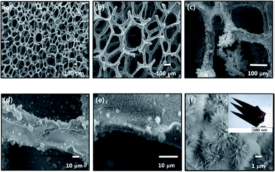 | ||
| Fig. 11 (a–f) SEM micrographs of CoxNi1−x(OH)2 on the graphene foam at different magnifications. The inset of panel f shows TEM of the CoxNi1−x(OH)2 material. Reproduced from ref. 112, with the permission of American Chemical Society. | ||
MWCNT paper was prepared by a floating catalyst chemical vapor deposition method (Fig. 12).113 NiCo LDH deposited onto the MWCNT paper has a nanoflake morphology with a thickness of 200 nm and a width of 3 nm. For Ni/Co at a 3/1 mole ratio, resulting in Co0.4Ni0.6(OH)2, uniform deposition was observed. CNTs with a larger diameter are good for uniform LDH deposition. The CNT/Co0.4Ni0.6(OH)2 electrode prepared with an active mass of 9.3 mg cm−2 has a specific capacitance of 2633 F g−1 at a current density of 0.7 A g−1 with a capacitance retention of 63.2% when the current density is increased to 14 A g−1. The specific capacitance of the CNT/Co0.4Ni0.6(OH)2 electrode reaches 107% after 500 charge discharge cycles at a current density of 2 A g−1.
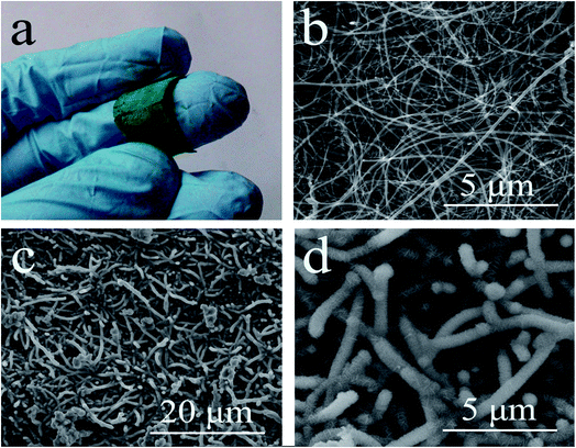 | ||
| Fig. 12 Optical image of CNT/Co0.4Ni0.6(OH)2 hybrid paper (a); surface morphology of pristine CNT paper (b); and CNT/Co0.4Ni0.6(OH)2 hybrid paper (c, d). Reproduced from ref. 113, with the permission of American Chemical Society. | ||
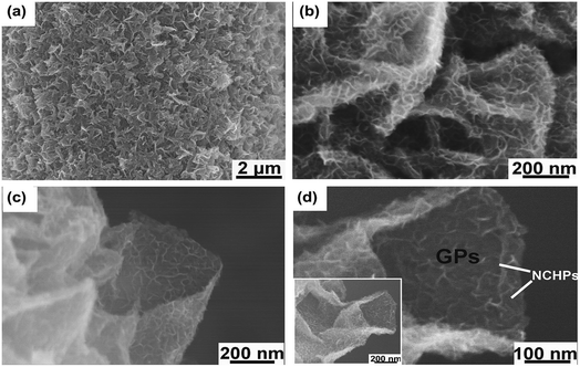 | ||
| Fig. 13 (a) GP foam uniformly covered by NCHPs at low magnification. (b) Smaller vertical NCHPs densely grown on relatively larger GPs (NCHP electrodeposition duration of 0.5 min). (c and d) Close-ups of a GP decorated by a large amount of smaller NCHPs. Reproduced from ref. 114, with permission of John Wiley and Sons. | ||
Exfoliated graphite foil (FEG) was prepared by an electrochemical exfoliation method, stuck to polyimide tape, and then NiCo LDH was deposited on the foil by chemical bath deposition.121 An electrode with an active mass of 0.44 mg cm−2 has a specific capacitance of 2442 F g−1 at a current density of 1 A g−1 with a capacitance retention of 85.5% at a high current density of 50 A g−1. When the active mass is increased to 1 mg cm−2, the specific capacitance decreases to 2011 F g−1. This is similar to what was observed for an electrode of CoNi(OH)2 integrated graphene foam, with a specific capacitances of 1847 F g−1 at 5 A g−1 and 1268 F g−1 at 60 A g−1 with 68.6% retention at a mass loading of 0.09 mg cm−2.112 NiCo LDH on ZnO nanowires with a mass loading of 0.9 mg cm−2 shows specific capacitances of 1624 F g−1 at a current density of 10 A g−1 and 1331 F g−1 at a current density of 50 A g−1, retention of 82%.92 NiCo LDH nanoflakes grown on ZnO nanowires integrated into carbon cloth with a mass loading of 0.98 g cm−2 show a specific capacitance of 1927 F g−1 at 2 A g−1 and 1546 F g−1 at 30 A g−1, with 81% capacitance retention.122
4. Conclusion
LDHs are an important class of materials for electrochemical storage applications. Numerous approaches, with various advantages and disadvantages, have been applied to fabricate electrodes with enhanced electrochemical performance. For example, when electrodes are prepared with a binder, it is easy to increase the amount of active material loading, which is useful for practical applications. In contrast, when electrodes are prepared using in situ methods, there may be limitations on increasing the active material loading.To improve the electrochemical performance of electrodes, a minimum active mass loading is required. The performance of electrodes needs to be at higher discharge current densities for practical applications. To realize enhanced electrode efficiency, the conductivity of the electrode also needs to be enhanced. It is possible to enhance the rate capability of an electrode either by modifying the current collector or by preparing a composite active material. The cycling stability of the electrode is another important factor that must be considered from an application point of view.
Conflicts of interest
There are no conflicts to declare.Acknowledgements
This research was supported by a National Research Foundation of Korea (NRF) grant funded by the Ministry of Science, ICT & Future Planning (NRF-2017R1C1B2010776 and NRF-2017R1A4A1014569).Notes and references
- J. P. Cheng, J. Zhang and F. Liu, RSC Adv., 2014, 4, 38893–38917 RSC.
- P. Simon and Y. Gogotsi, Nat. Mater., 2008, 7, 845–854 CrossRef CAS PubMed.
- G. Wang, L. Zhang and J. Zhang, Chem. Soc. Rev., 2012, 41, 797–828 RSC.
- C. Yuan, H. B. Wu, Y. Xi and X. W. Lou, Angew. Chem., Int. Ed., 2014, 53, 1488–1504 CrossRef CAS PubMed.
- K. Watanabe, T. Kikuoka and N. Kumagi, J. Appl. Electrochem., 1995, 25, 219–226 CrossRef CAS.
- J. Che, D. H. Bradhust, S. X. Dou and H. K. Liu, J. Electrochem. Soc., 1999, 146, 3606–3612 CrossRef.
- A. M. Elshahawy, K. H. Ho, Y. Hu, Z. Fan, Y. W. B. Hsu, C. Guan, Q. Ke and J. Wang, CrystEngComm, 2016, 18, 3256–3264 RSC.
- H. Du, Y. Wang, H. Yuan and L. Jiao, Electrochim. Acta, 2016, 196, 84–91 CrossRef CAS.
- Z. Jia, W. Lu, Y. Wang, Y. Liang, Y. Li and S. Feng, Electrochim. Acta, 2015, 159, 35–39 CrossRef CAS.
- Y. Tao, C. Jinfei, Y. Tingting and L. Zaijun, Mater. Res. Bull., 2014, 60, 612–620 CrossRef CAS.
- H. Jiang, T. Zhao, C. Li and J. Ma, J. Mater. Chem., 2011, 21, 3818–3823 RSC.
- X. Zhou, D. Cao, J. Huang, K. Ye, S. Yang, T. Liu, X. Liu, J. Yin and G. Wang, J. Electroanal. Chem., 2014, 720–721, 115–120 CrossRef CAS.
- Z. Lu, Z. Chang, W. Zhu and X. Sun, Chem. Commun., 2011, 47, 9651–9653 RSC.
- L. Hu, Z. Yu, Z. Hu, Y. Song, F. Zhang, H. Zhua and S. Jiao, Electrochim. Acta, 2015, 174, 273–281 CrossRef CAS.
- H. Niu, D. Zhou, X. Yang, X. Li, Q. Wang and F. Qu, J. Mater. Chem. A, 2015, 3, 18413–18421 CAS.
- Y.-Z. Su, K. Xiao, N. Li, Z.-Q. Liu and S.-Z. Qiao, J. Mater. Chem. A, 2014, 2, 13845–13853 CAS.
- I.-C. Chang, T.-T. Chen, M.-H. Yang, H.-T. Chiu and C.-Y. Lee, J. Mater. Chem. A, 2014, 2, 10370–10374 CAS.
- K. Wang, X. Zhang, X. Zhang, D. Chen and Q. Lin, J. Power Sources, 2016, 333, 156–163 CrossRef CAS.
- J. Kim, Y. Kim, S.-J. Park, Y. Jung and S. Kim, J. Ind. Eng. Chem., 2016, 36, 139–146 CrossRef CAS.
- L.-L. Zhang, H.-H. Li, C.-Y. Fan, K. Wang, X.-L. Wu, H.-Z. Sun and J.-P. Zhang, J. Mater. Chem. A, 2015, 3, 19077–19084 CAS.
- Z. Wu, X.-L. Huang, Z.-L. Wang, J.-J. Xu, H.-G. Wang and X.-B. Zhang, Sci. Rep., 2014, 4, 3669 CrossRef PubMed.
- X. Wang, J. Liu, Y. Wang, C. Zhao and W. Zheng, Mater. Res. Bull., 2014, 52, 89–95 CrossRef CAS.
- F. Zhang, D. Zhu, X. Chen, X. Xu, Z. Yang, C. Zou, K. Yang and S. Huang, Phys. Chem. Chem. Phys., 2014, 16, 4186–4192 RSC.
- Z. Yang, C. Fang, Y. Fang and F. Zhu, Int. J. Electrochem. Sci., 2015, 10, 1574–1581 CAS.
- C. Jiang, B. Zhao, J. Cheng, J. Li, H. Zhang, Z. Tang and J. Yang, Electrochim. Acta, 2015, 173, 399–407 CrossRef CAS.
- Y. Tang, Y. Liu, W. Guo, T. Chen, H. Wang, S. Yu and F. Gao, J. Phys. Chem. C, 2014, 118, 24866–24876 CAS.
- S. Min, C. Zhao, Z. Zhang, G. Chen, X. Qian and Z. Guo, J. Mater. Chem. A, 2015, 3, 3641–3650 CAS.
- H. Yi, H. Wang, Y. Jing, Y. Wang and J. Guo, J. Mater. Chem. A, 2015, 3, 19545–19555 CAS.
- V. Pralong, A. Delahaye-Vidal, B. Beaudoin, J.-B. Leriche and J.-M. Tarascon, J. Electrochem. Soc., 2000, 147, 1306–1313 CrossRef CAS.
- C. Yuan, L. Hou, L. Shen, D. Li, F. Zhang, C. Fan, J. Li and X. Zhang, Electrochim. Acta, 2010, 56, 115–121 CrossRef CAS.
- R. R. Salunkhe, B. P. Bastakoti, C.-T. Hsu, N. Suzuki, J. H. Kim, S. X. Dou, C.-C. Hu and Y. Yamauchi, Chem.–Eur. J., 2014, 20, 3084–3088 CrossRef CAS PubMed.
- L.-B. Kong, M. Liu, J.-W. Lang, Y.-C. Luo and L. Kang, J. Electrochem. Soc., 2009, 156(12), A1000–A1004 CrossRef CAS.
- W.-J. Zhou, M.-W. Xu, D.-D. Zhao, C.-L. Xu and H.-L. Li, Microporous Mesoporous Mater., 2009, 117, 55–60 CrossRef CAS.
- J.-K. Chang, C.-M. Wub and I.-W. Sun, J. Mater. Chem., 2010, 20, 3729–3735 RSC.
- C. Yuan, X. Zhang, L. Hou, L. Shen, D. Li, F. Zhang, C. Fan and J. Li, J. Mater. Chem., 2010, 20, 10809–10816 RSC.
- A.-A. M. Barmi, M. Aghazadeh, B. Arhami, H. M. Shiri, A. A. Fazl and E. Jangju, Chem. Phys. Lett., 2012, 541, 65–69 CrossRef.
- M.-J. Deng, C.-Z. Song, C.-C. Wang, Y.-C. Tseng, J.-M. Chen and K.-T. Lu, ACS Appl. Mater. Interfaces, 2015, 7, 9147–9156 CAS.
- T. Xue, X. Wang and J.-M. Lee, J. Power Sources, 2012, 201, 382–386 CrossRef CAS.
- Q. Huang, J. Wang, F. Liu, X. Chang, H. Chen, H. Lin and S. Han, RSC Adv., 2016, 6, 16745–16750 RSC.
- J. Xue, W. Ma, F. Zhang, M. Wang and H. Cui, Solid State Ionics, 2015, 281, 38–42 CrossRef CAS.
- G. X. Pan, X. Xia, F. Cao, P. S. Tang and H. F. Chen, Electrochim. Acta, 2012, 63, 335–340 CrossRef CAS.
- D. Tai Dam and J.-M. Lee, Nano Energy, 2013, 2, 1186–1196 CrossRef CAS.
- J. Tang, D. Liu, Y. Zheng, X. Li, X. Wang and D. He, J. Mater. Chem. A, 2014, 2, 2585–2591 CAS.
- H. B. Liu, L. Xiang and Y. Jin, Cryst. Growth Des., 2006, 6, 283–286 CAS.
- G. Chen, S. S. Liaw, B. Li, Y. Xu, M. Dunwell, S. Deng, H. Fan and H. Luo, J. Power Sources, 2014, 251, 338–343 CrossRef CAS.
- X. Sun, G. Wang, H. Sun, F. Lu, M. Yu and J. Lian, J. Power Sources, 2013, 238, 150–156 CrossRef CAS.
- W. Zhu, Z. Lu, G. Zhang, X. Lei, Z. Chang, J. Liu and X. Sun, J. Mater. Chem. A, 2013, 1, 8327–8331 CAS.
- M. F. Warsi, I. Shakir, M. Sahid, M. Sarfraz, M. Nadeem and Z. A. Gilani, Electrochim. Acta, 2014, 135, 513–518 CrossRef CAS.
- Y. Tang, Y. Liu, S. Yu, W. Guo, S. Mu, H. Wang, Y. Zhao, L. Hou, Y. Fan and F. Gao, Electrochim. Acta, 2015, 161, 279–289 CrossRef CAS.
- C.-C. Hu and C.-Y. Cheng, Electrochem. Solid-State Lett., 2002, 5(3), A43–A46 CrossRef CAS.
- T. Brousse, D. B'elanger and J. W. Long, J. Electrochem. Soc., 2015, 162, A5185–A5189 CrossRef CAS.
- P. Simon, Y. Gogosti and B. Dunn, Science, 2014, 343, 1210–1211 CrossRef CAS PubMed.
- C. Wang, X. Zhang, Z. Xu, X. Sun and Y. Ma, ACS Appl. Mater. Interfaces, 2015, 7, 19601–19610 CAS.
- C. Shang, S. Dong, S. Wang, D. Xiao, P. Han, X. Wang, L. Gu and G. Cui, ACS Nano, 2013, 7, 5430–5436 CrossRef CAS PubMed.
- Y. Tao, L. Zaijun, L. Ruiyi, N. Qi, K. Hui, N. Yulian and L. Junkang, J. Mater. Chem., 2012, 22, 23587–23592 RSC.
- X. Liu, R. Ma, Y. Bando and T. Sasaki, Adv. Mater., 2012, 24, 2148–2153 CrossRef CAS PubMed.
- Z. A. Hu, Y. L. Xie, Y. X. Wang, H. Y. Wu, Y. Y. Yang and Z. Y. Zhang, Electrochim. Acta, 2009, 54, 2737–2741 CrossRef CAS.
- V. Gupta, S. Gupta and N. Miura, J. Power Sources, 2008, 175, 680–685 CrossRef CAS.
- D. P. Dubal, P. Gomez-Romero, B. R. Sankapal and R. Holze, Nano Energy, 2015, 11, 377–399 CrossRef CAS.
- G. P. Wang, L. Zhang, J. Kim and J. J. Zhang, J. Power Sources, 2012, 217, 554–561 CrossRef CAS.
- H. Chen, J. Jiang, L. Zhang, Y. Zhao, D. Guo, Y. Ruan and D. Xia, ChemPlusChem, 2015, 80, 181–187 CrossRef CAS.
- D. Xia, H. Chen, J. Jiang, L. Zhang, Y. Zhao, D. Guo and J. Yu, Electrochim. Acta, 2015, 156, 108–114 CrossRef CAS.
- L. Wang, Z. H. Dong, Z. G. Wang, F. X. Zhang and J. Jin, Adv. Funct. Mater., 2013, 23, 2758–2764 CrossRef CAS.
- B. P. Bastakoti, H. S. Huang, L. C. Chen, K. C.-W. Wu and Y. Yamauchi, Chem. Commun., 2012, 48, 9150–9152 RSC.
- J. W. Lee, T. Ahn, D. Soundararajan, J. M. Ko and J. D. Kim, Chem. Commun., 2011, 47, 6305–6307 RSC.
- J. Han, K. C. Roh, M. R. Jo and Y.-M. Kang, Chem. Commun., 2013, 49, 7067–7069 RSC.
- H. Chen, J. Jiang, L. Zhang, T. Qi, D. Xia and H. Wan, J. Power Sources, 2014, 248, 28–36 CrossRef CAS.
- X. Y. Liu, Y. Q. Zhang, X. H. Xia, S. J. Shi, Y. Lu, X. L. Wang, C. D. Gu and J. P. Tu, J. Power Sources, 2013, 239, 157–163 CrossRef CAS.
- H. Wang, Q. Gao and L. Jiang, Small, 2011, 7, 2454–2459 CAS.
- J. Xiao and S. Yang, RSC Adv., 2011, 1, 588–595 RSC.
- H.-W. Wang, Z.-A. Hu, Y.-Q. Chang, Y.-L. Chen, H.-Y. Wu, Z.-Y. Zhang and Y.-Y. Yang, J. Mater. Chem., 2011, 21, 10504–10511 RSC.
- J. Wang, Y. C. Song, Z. S. Li, Q. Liu, J. D. Zhou, X. Y. Jing, M. L. Zhang and Z. H. Jiang, Energy Fuels, 2010, 24, 6463–6467 CrossRef CAS.
- X. Zhu, H. Dai, J. Hu, L. Ding and L. Jiang, J. Power Sources, 2012, 203, 243–249 CrossRef CAS.
- X. Su, Y. Xu, J. Liu and R. Wang, CrystEngComm, 2015, 17, 4859–4865 RSC.
- J. Zhang, J. P. Cheng, M. Li, L. Liu and X. B. Zhang, J. Electroanal. Chem., 2015, 743, 38–45 CrossRef CAS.
- J. Xu, Y. Dong, J. Cao, B. Guo, W. Wang and Z. Chen, Electrochim. Acta, 2013, 114, 76–82 CrossRef CAS.
- D. Zhou, X. Su, M. Boese, R. Wang and H. Zhang, Nano Energy, 2014, 5, 52–59 CrossRef CAS.
- J. Li, M. Yang, J. Wei and Z. Zhou, Nanoscale, 2012, 4, 4498–4503 RSC.
- C. Wang, X. Zhang, X. Sun and Y. Ma, Electrochim. Acta, 2016, 191, 329–336 CrossRef CAS.
- L. Xie, Z. Hu, C. Lv, G. Sun, J. Wang, Y. Li, H. He, J. Wang and K. Li, Electrochim. Acta, 2012, 78, 205–211 CrossRef CAS.
- M. Wang, J. Xue, F. Zhang, W. Ma and H. Cui, J. Nanopart. Res., 2015, 17, 106 CrossRef.
- T. Li, G. H. Li, L. H. Li, L. Liu, Y. Xu, H. Y. Ding and T. Zhang, ACS Appl. Mater. Interfaces, 2016, 8, 2562–2572 CAS.
- X. Cai, X. Shen, L. Ma, Z. Ji, C. Xu and A. Yuan, Chem. Eng. J., 2015, 268, 251–259 CrossRef CAS.
- H. Ma, J. He, D.-B. Xiong, J. Wu, Q. Li, V. Dravid and Y. Zhao, ACS Appl. Mater. Interfaces, 2016, 8, 1992–2000 CAS.
- S. N. Tiruneh, B. K. Kang, Q. T. Ngoc and D. H. Yoon, RSC Adv., 2016, 6, 4764–4769 RSC.
- K. Subramani, N. Lakshminarasimhan, P. Kamaraj and M. Sathish, RSC Adv., 2016, 6, 15941–15951 RSC.
- Y. Tao, L. Ruiyi and L. Zaijun, Mater. Res. Bull., 2014, 51, 97–104 CrossRef.
- M. Li, K. Y. Ma, J. P. Cheng, D. Lv and X. B. Cheng, J. Power Sources, 2015, 286, 438–444 CrossRef CAS.
- L. Huang, D. Chen, Y. Ding, S. Feng, Z. L. Wang and M. Liu, Nano Lett., 2013, 13, 3135–3139 CrossRef CAS PubMed.
- J. Liu, C. Cheng, W. Zhou, H. Li and H. J. Fan, Chem. Commun., 2011, 47, 3436–3438 RSC.
- H. Chen, L. Hu, M. Chen, Y. Yan and L. Wu, Adv. Funct. Mater., 2014, 24, 934–942 CrossRef CAS.
- N. T. H. Trang, H. V. Ngoc, N. Lingappan and D. J. Kang, Nanoscale, 2014, 6, 2434–2439 RSC.
- W. Zhou, K. Yu, D. Wang, J. Chu, J. Li, L. Zhao, C. Ding, Y. Du, X. Jia, H. Wang and G. Wen, Nanotechnology, 2016, 27, 235402 CrossRef PubMed.
- W. Quan, Z. Tang, Y. Hong, S. Wang and Z. Zhang, Electrochim. Acta, 2015, 182, 445–451 CrossRef CAS.
- L. Ye, L. Zhao, H. Zhang, B. Zhang and H. Wang, J. Mater. Chem. A, 2016, 4, 9160–9168 CAS.
- J. Pu, Y. Tong, S. Wang, E. Sheng and Z. Wang, J. Power Sources, 2014, 250, 250–256 CrossRef CAS.
- R. R. Salunkhe, K. Jang, S.-W. Lee and H. Ahn, RSC Adv., 2012, 2, 3190–3193 RSC.
- X. Zheng, Z. Gu, Q. Hu, B. Geng and X. Zhang, RSC Adv., 2015, 5, 17007–17013 RSC.
- R. R. Salunkhe, K. Jang, S.-W. Lee, S. Yu and H. Ahn, J. Mater. Chem., 2012, 22, 21630–21635 RSC.
- X. Liu, J. Huang, X. Wei, C. Yuan, T. Liu, D. Cao, J. Yin and G. Wang, J. Power Sources, 2013, 240, 338–343 CrossRef CAS.
- L. Wan, J. Xiao, F. Xiao and S. Wang, ACS Appl. Mater. Interfaces, 2014, 6, 7735–7742 CAS.
- J. Wu, W.-W. Liu, Y. X. Wu, T.-C. Wei, D. Geng, J. Mei, H. Liu, W.-M. Lau and L.-M. Liu, Electrochim. Acta, 2016, 203, 21–29 CrossRef CAS.
- X. Li, J. Shen, W. Sun, X. Hong, R. Wang, X. Zhao and X. Yan, J. Mater. Chem. A, 2015, 3, 13244–13253 CAS.
- K. Xu, R. Zou, W. Li, Q. liu, X. Liu, L. An and J. Hu, J. Mater. Chem. A, 2014, 2, 10090–10092 CAS.
- Z.-Q. Liu, G.-F. Chen, P.-L. Zhou, N. Li and Y.-Z. Su, J. Power Sources, 2016, 317, 1–9 CrossRef CAS.
- M. Yang, H. Cheng, Y. Gu, Z. Sun, Z. Sun, J. Hu, L. Cao, F. Lv, M. Li, W. Wang, Z. Wang, S. Wu, H. Liu and Z. Lu, Nano Res., 2015, 8, 2744–2754 CrossRef CAS.
- G. Nagaraju, G. S. R. Raju, Y. H. Ko and J. S. Yu, Nanoscale, 2016, 8, 812–825 RSC.
- J. Chen, J. Xu, S. Zhou, N. Zhao and C.-P. Wong, Nano Energy, 2016, 21, 145–153 CrossRef CAS.
- M. Jing, H. Hou, C. E. Banks, Y. Ynag, Y. Zhang and X. Ji, ACS Appl. Mater. Interfaces, 2015, 7, 22741–22744 CAS.
- S. B. Kulkarni, A. D. Jagadale, V. S. Kumbhar, R. N. Bulakhe, S. S. Joshi and C. D. Lokhande, Int. J. Hydrogen Energy, 2013, 38, 4046–4053 CrossRef CAS.
- Y. Cheng, H. Zhang, C. V. Varanasi and J. Liu, Energy Environ. Sci., 2013, 6, 3314–3321 CAS.
- U. M. Patil, J. S. Sohn, S. B. Kulkarni, S. C. Lee, H. G. Park, K. V. Gurav, J. H. Kim and S. C. Jun, ACS Appl. Mater. Interfaces, 2014, 6, 2450–2458 CAS.
- H. Chen, L. Hu, M. Chen, Y. Yan and L. Wu, ACS Appl. Mater. Interfaces, 2014, 6, 19630–19637 CAS.
- G. Xiong, P. He, D. Wang, Q. Zhang, T. Chen and T. S. Fisher, Adv. Funct. Mater., 2016, 26, 5460–5470 CrossRef CAS.
- J. Y. Ji, L. L. Zhang, H. X. Ji, Y. Li, X. Zhao, X. Bai, X. B. Fan, F. B. Zhang and R. S. Ruoff, ACS Nano, 2013, 7, 6237–6243 CrossRef CAS PubMed.
- G. P. Xiong, C. Z. Meng, R. G. Reifenberger, P. P. Irazoqui and T. S. Fisher, Adv. Energy Mater., 2014, 4, 1300515 CrossRef.
- C. Emmenegger, P. Mauron, P. Sudan, P. Wenger, V. Hermann, R. Gallay and A. Zuttel, J. Power Sources, 2003, 124, 321–329 CrossRef CAS.
- D. W. Wang, F. Li, J. P. Zhao, W. C. Ren, Z. G. Chen, J. Tan, Z. S. Wu, I. Gentle, G. Q. Lu and H. M. Cheng, ACS Nano, 2009, 3, 1745–1752 CrossRef CAS PubMed.
- M. Heon, S. Lofland, J. Applegate, R. Nolte, E. Cortes, J. D. Hettinger, P. L. Taberna, P. Simon, P. H. Huang, M. Brunet and Y. Gogotsi, Energy Environ. Sci., 2011, 4, 135–138 CAS.
- M. Q. Zhao, C. E. Ren, Z. Ling, M. R. Lukatskaya, C. F. Zhang, K. L. Van Aken, M. W. Barsoum and Y. Gogotsi, Adv. Mater., 2015, 27, 339–345 CrossRef CAS PubMed.
- Y. Song, X. Cai, X. Xu and X. X. Lui, J. Mater. Chem. A, 2015, 3, 14712–14720 CAS.
- I. Shakir, M. Shahid, U. A. Rana, I. M. A. Nashef and R. Hussain, Electrochim. Acta, 2014, 129, 28–32 CrossRef CAS.
| This journal is © The Royal Society of Chemistry 2018 |


