
3D hierarchical CoO@MnO2 core–shell nanohybrid for high-energy solid state asymmetric supercapacitors†
Chao
Li
a,
Jayaraman
Balamurugan
a,
Tran Duy
Thanh
a,
Nam Hoon
Kim
*a and
Joong Hee
Lee
*ab
aAdvanced Materials Institute of BIN Convergence Technology (BK21 Plus Global), Dept. of BIN Convergence Technology, Chonbuk National University, Jeonju, Jeonbuk 54896, Republic of Korea. E-mail: jhl@chonbuk.ac.kr; nhk@chonbuk.ac.kr; Fax: +82 832702341; Tel: +82 832702301
bCarbon Composite Research Centre, Department of Polymer Nano Science and Technology, Chonbuk National University, Jeonju, Jeonbuk 54896, Republic of Korea
First published on 21st November 2016
Abstract
A unique morphology, high specific surface area, extraordinary porosity, and excellent conductive networks are typical favorable properties of pseudocapacitors; however, fully comprehending and interpreting this substantive topic still remains a great challenge. Herein, we present a new strategy for the direct growth of a cobalt monoxide@manganese oxide core–shell nanostructure on 3D Ni foam (CoO@MnO2/Ni foam). This is accomplished by simple, scalable, in situ fabrication methods to produce a material that can be employed as an advanced electrode material for high-energy solid state asymmetric supercapacitors (ASCs). The cost-effective, binder-free 3D CoO@MnO2 core–shell nanostructure delivers excellent electrochemical properties with an ultra-high specific capacitance (1835 F g−1 at a current density of 1 A g−1), tremendous rate capabilities with an extraordinary capacitance of 1198 F g−1 at a current density of 20 A g−1, and outstanding stability (97.7% capacitance retention after 10![[thin space (1/6-em)]](https://www.rsc.org/images/entities/char_2009.gif) 000 cycles). ASCs with a maximum potential window of 1.8 V are fabricated by using a 3D CoO@MnO2 core–shell nanohybrid as the positive electrode and N-doped graphene (NG) as the negative electrode in order to validate the outstanding performance for practical energy storage devices. Impressively, the ASCs delivered a high specific capacitance (191 F g−1 at 1 A g−1), excellent energy density (∼85.9 W h kg−1), an ultra-high power density (∼16769 W kg−1 at 51.7 W h kg−1), and remarkable cycle stability (86.8% capacitance retention after 10000 cycles). These findings provide a new method to design 3D CoO@MnO2 core–shell nanostructures that are cost-effective and binder-free electrode materials for the development of high-performance energy storage devices.
000 cycles). ASCs with a maximum potential window of 1.8 V are fabricated by using a 3D CoO@MnO2 core–shell nanohybrid as the positive electrode and N-doped graphene (NG) as the negative electrode in order to validate the outstanding performance for practical energy storage devices. Impressively, the ASCs delivered a high specific capacitance (191 F g−1 at 1 A g−1), excellent energy density (∼85.9 W h kg−1), an ultra-high power density (∼16769 W kg−1 at 51.7 W h kg−1), and remarkable cycle stability (86.8% capacitance retention after 10000 cycles). These findings provide a new method to design 3D CoO@MnO2 core–shell nanostructures that are cost-effective and binder-free electrode materials for the development of high-performance energy storage devices.
Introduction
Extensive research efforts have been dedicated to the exploration of cost-effective, high-energy, high power density, and environmentally friendly energy storage devices in order to meet the increasing demands of portable electronic devices and electrical vehicles.1–3 Among electrochemical energy storage devices, supercapacitors have received extensive attention in view of their excellent features, including their high power density (>10 kW kg−1), fast charge–discharge rate, long cycle life, and excellent safety.4–7 However, even though they have these benefits, their large-scale applications are constrained by their limited energy density.8 Subsequently, in order to continue to expand their applications, it is imperative to obtain advanced supercapacitors with higher energy densities while also maintaining the power density and cycling stability.9 In recent years, asymmetric supercapacitors (ASCs), which typically consist of electrical double layers and pseudocapacitive materials, have gained increased interest due to their improved energy densities.10 The novel structures of ASCs lead to their enhanced energy storage performance (due to the pseudocapacitive electrode materials) and a wider operating potential window, both of which can lead to higher energy densities.11–13 Furthermore, it is well-known that the performance of ASCs directly depends upon the structure and properties of the supercapacitive electrode materials.14 Depending upon the synthesis of high-quality electrode materials, high energy density ASCs have been developed.In attempts to improve the performance of ASCs, several efforts have been funded to develop pseudocapacitive transition metal oxides. These materials are attractive due to their distinct properties, which can enhance the specific capacitance and energy density when combined with carbon-based materials that possess electrical double layer capacitance.15 Specifically, transition metal oxides, including RuO2, Co3O4, NiO, Fe2O3, and MnO2, have shown promise as advanced electrodes for ASCs because of their achievable oxidation states, superior electrical conductivity, and high electrocatalytic activity. These characteristics are crucial for the production of practical ASCs.16–19 Among these transition metal oxides, MnO2 and Co3O4 are particularly attractive due to their easy fabrication, low cost, desirable pseudocapacitive properties, tunable surface and structural properties, abundance in nature, environmental friendliness, and high theoretical capacitance.20,21 Nevertheless, MnO2 has poor electrical conductivity (10−5 to 10−6 S cm−1) and low surface area. Additionally, Co3O4 suffers from deprived capacity retention and rate capacity, which can significantly impede its practical application in ASCs.22,23 To solve these problems, designs based on MnO2 nanohybrids have been employed by utilizing highly conducting supports such as carbon nanotubes,24,25 graphene,26–28 and polymer matrices.29,30 Alternatively, assimilation of the Co3O4/MnO2 nanohybrid via smart fabrication enhances the electrochemical performance because of the synergistic interactions between components. For example, Liu et al.31 showed that Co3O4 nanowire@MnO2 ultrathin nanosheet core-shells on Ni foam presented higher electrochemical performance (with a specific capacitance of 480 F g−1 at 2.67 A g−1). Kong et al.32 reported that Co3O4@MnO2 hierarchical nanoneedles on Ni foam showed enhanced electrochemical performance (with a specific capacitance of 1693.2 F g−1 at 1 A g−1). However, to the best of our knowledge, cobalt monoxide (CoO; a relatively new type of cobalt oxide) has never been employed as the core material (with a MnO2 shell) for the fabrication of pseudocapacitors. This material has proven to be quite difficult to synthesize. However, CoO possesses an extraordinary theoretical capacitance (∼4292 F g−1) and has been used as a conductive interlayer material to intensify the conductivity of Ni–H batteries in a KOH aqueous electrolyte.33,34 To enhance the active surface area, we found another method that facilitates the formation of Co–O sites; this relies on the active atoms at the interface of the second phase of MnO2 and can be used to form a super structure. A key challenge is the fabrication of CoO@MnO2 with an integrated smart 3D architecture that can be used to replace the Co3O4@MnO2 core–shell structure in energy storage devices.
To the best of our knowledge, the direct growth of the 3D CoO@MnO2 core–shell nanohybrid on Ni foam for high-performance ASCs has not been reported until now. Here, a simple, scalable, and cost-effective in situ fabrication method is effectively established to control the synthesis of the 3D CoO@MnO2 core–shell nanohybrid on Ni foam conductive substrates. It is found that the nature of the metal oxide can be easily controlled to be CoO or Co3O4 by altering the reaction conditions. As anticipated, two different nanostructures can be combined to create binder-free electrodes for supercapacitors that ensure high pseudocapacitance properties. Furthermore, ASCs based on the as-synthesized 3D CoO@MnO2 core–shell nanohybrid (as the positive electrode) and nitrogen-doped graphene (NG) (as the negative electrode) have been successfully assembled. The fabricated ASCs deliver an excellent energy density of 85.9 W h kg−1 at a power density of 852.4 W kg−1. They also demonstrated outstanding cycling stability with capacitance retention of 86.8% after 10000 cycles at a wide operating potential of 1.8 V.
Experimental
Synthesis of the 3D CoO@MnO2 core–shell nanohybrid
All of the purchased chemicals were analytical grade and used without further purification. In a typical procedure, 1.45 g of Co(NO3)2·6H2O was dissolved in 50 mL of deionized (DI) water. 1.51 g of CO(NH2)2 was then added into the mixture and the solution was stirred for 10 min to obtain a clear, pink-red solution. The precursor solution was transferred into a 100 mL Teflon-lined stainless steel autoclave. A piece of Ni foam (2 cm × 5 cm) was treated with 3 M HCl, DI water, absolute ethanol, and acetone (30 min each), respectively, to remove the oxidized layer and other organic impurities prior to use as a substrate. For in situ CoO NWs growth, the cleaned Ni foam was immersed into the solution. Subsequently, the autoclave was sealed, maintained at 100 °C for 8 h, and then cooled down to the room temperature naturally. Then, the as-prepared material was rinsed with DI water and ethanol several times to remove any weakly attached material. The product was then dried at 60 °C for 6 h in an electrical oven. The as-synthesized materials were annealed at 450 °C under an argon atmosphere for 4 h to obtain CoO NWs/Ni foam. The as-prepared CoO NWs/Ni foam was directly used as the scaffold to grow the MnO2 nanosheet array via a carbon-assisted reaction process. In a typical process, a piece of CoO NWs/Ni foam was immersed into a 0.04 M aqueous glucose solution for 24 h. This was followed by carbonization at 450 °C under an argon atmosphere for 2 h. After carbon deposition, the CoO NW array was put inside the Teflon-lined stainless steel autoclave in a 0.03 M KMnO4 solution. This was sealed and held at 160 °C for 5 h. The final as-synthesized materials were washed with DI water and ethanol alternately and then dried at 60 °C for 8 h to obtain the 3D CoO@MnO2 core–shell nanohybrid.Material characterizations
The morphology and structure of the as-synthesized materials were characterized by field emission scanning electron microscopy (FE-SEM) and transmission electron microscopy (TEM). The FE-SEM images, energy dispersive X-ray analysis (EDAX) and FESEM-EDS mapping were recorded by using a JSM-6701F instrument (JEOL Co., Japan) installed in the Center for University-Wide Research Facilities (CURF) at Chonbuk National University. The TEM images, high-resolution TEM (HR-TEM) images and energy dispersive X-ray spectroscopy (EDS) mapping were recorded using an H-7650 (Hitachi Ltd, Japan) in the Jeonju center at KBSI. Powder X-ray diffraction (XRD) patterns were obtained on a D/Max 2500V/PC (Rigaku Corporation, Japan, Cu Kα radiation (λ = 0.154 nm)). The surface states of the materials were analyzed by X-ray photoelectron spectroscopy (XPS; Thermo Fisher Scientific, UK), and using N2 sorption isotherms (Micromeritics Tristar 3000 analyzer).Electrochemical characterizations
Electrochemical studies of individual fabricated CoO NWs and 3D CoO@MnO2 core–shell electrodes as the working electrode using aqueous 6 M KOH as the electrolyte, Pt foil as the counter electrode, and Ag/AgCl as the reference electrode were executed in a three-electrode system. The as-synthesized CoO NWs and 3D CoO@MnO2 core–shell nanohybrid on Ni foam (Selectrode = 1.5 cm × 1.5 cm, mCoO ≈ 2.8 mg, mCoO@MnO2 ≈ 4.8 mg) were used directly as the working electrode. The ASCs were measured with a two-electrode system, which included two slices of electrode material with the same size, NKK TF40 (40 μm thickness, Nippon Kodoshi Corporation) as the separator, and KOH/PVA gel as the solid state electrolyte. In the two-electrode system, the hierarchical 3D CoO@MnO2 core–shell nanohybrid was the positive electrode, and NG was the negative electrode, which we have used in previous work.35 The KOH/PVA gel electrolyte was prepared using the following procedure: 3 g KOH and 6 g PVA (Mw = 15000) were dissolved in 60 mL DI water and then heated at 85 °C for 1 h under vigorous stirring. The electrodes and separator were soaked in the electrolyte for 10 min and then allowed to solidify at room temperature for 6 h. Finally, the assembled ASCs were heated at 45 °C for 12 h in an oven to remove the excess of water. The operating current densities of the three-electrode system and ASCs were calculated based on the mass of active materials (i.e. mass of CoO NWs or 3D CoO@MnO2 core–shell nanohybrid for the three-electrode system; total weight of 3D CoO@MnO2 core–shell nanohybrid with NG for the two electrode system). Electrochemical characterization, including cyclic voltammetry (CV) and galvanostatic charge–discharge (GCD), was carried out using an electrochemical work station (CHI 660D, USA). Electrochemical impedance spectroscopy (EIS) was accomplished using the same electrochemical work station using an open-circuit potential in the frequency range between 100 kHz and 0.01 Hz under ambient conditions. The specific capacitances of as-synthesized CoO NWs and 3D CoO@MnO2 core–shell nanohybrid in the three-electrode system and ASC devices were calculated using the following eqn (1).36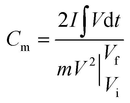 | (1) |
 is the area under the experimental curve, V is the potential with initial and final values of Vi and Vf, respectively.
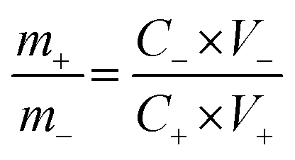
The ASCs were fabricated using the 3D CoO@MnO2 core–shell nanohybrid as the positive electrode material and NG as the negative electrode. In order to achieve high electrochemical performance for ASCs, the mass ratio of the 3D CoO@MnO2 core–shell nanohybrid to NG and the voltage window were optimized to ∼0.33 and 1.8 V, respectively. The optimal mass ratio of the 3D CoO@MnO2 core–shell nanohybrid to NG was calculated according to their capacitance values obtained from eqn (2):
 | (2) |
The electrochemical performance of the ASCs was evaluated by CV and GCD testing to verify the practical energy storage device applications. The energy density (E) and power density (P) were calculated with eqn (3) and (4):
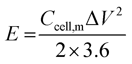 | (3) |
 | (4) |
Results and discussion
The 3D CoO@MnO2 core–shell nanohybrid supported on Ni foam was fabricated by a simple, in situ, two-step method, as illustrated in Scheme 1. For the first step, CoO NWs are directly grown on Ni foam via a facile hydrothermal method with a successive post-annealing process. After hydrothermal treatment at 100 °C for 8 h, the cobalt precursor is uniformly grown on Ni foam, establishing the nanowire structure. Subsequently, the CoO architecture was formed by a post-annealing treatment at 450 °C under an argon atmosphere for 4 h. | ||
| Scheme 1 Schematic illustration for the fabrication and application of the 3D CoO@MnO2 core–shell nanohybrid. | ||
The proposed mechanism for the CoO NWs, which were formed via a hydrothermal reaction with a post-annealing treatment, can be expressed as follows:37,38
| CO(NH2)2 + H2O → NH3 + CO2 | (5) |
| CO2 + H2O → CO32− + H+ | (6) |
| NH3·H2O → NH4+ + OH− | (7) |
| Co2+ + 0.5CO32− + OH− + 0.11H2O→ Co(CO3)0.5(OH)·0.11H2O | (8) |
| 2Co(CO3)0.5(OH)·0.11H2O → 2CoO + 1.22H2O + CO2 | (9) |
When the reaction temperature increases to around 70 °C, the urea in the precursor solution starts to hydrolyze, which generates large amounts of OH− and CO32−. When the temperature ramps up to 100 °C, the hydrolysis rate of urea will be accelerated and the concentration of OH− and CO32− will be increased. Further reaction of Co2+, CO32−, and OH− controls the formation of nuclei on the Ni foam surface. During the hydrothermal process, nuclei begin to assemble and form the nanowire superstructure. After the annealing treatment at 450 °C for 4 h in an Ar atmosphere, CoO NWs are fully converted into a highly porous architecture. In the next step, the MnO2 nanosheet array grows over the surface of the CoO NWs. The as-prepared, porous, highly ordered CoO NWs/Ni foam are then impregnated with a glucose aqueous solution and successively post-annealed in an Ar atmosphere.
The carbon coatings over the CoO NWs are analysed by FE-SEM and EDS colour mapping (Fig. S1†). The FE-SEM and EDS colour mapping revealed that the carbon layers are uniformly coated over the CoO NWs. The coated carbon layers act as templates to decorate the MnO2 nanosheets on the surface of CoO NWs. This process relies on the fact that MnO2 can be formed by an interfacial reaction between amorphous carbon and KMnO4 at ambient temperatures without any acidic or basic media (4MnO4− + 3C + H2O = 4MnO2 + CO32− + 2HCO3−).39,40 After the treatment with MnO2, the CoO NWs maintained their original structure and the 3D hierarchical CoO@MnO2 core–shell nanohybrid on Ni foam can be synthesized.
FE-SEM and TEM studies are employed to investigate the surface morphology and intrinsic morphology of the as-synthesized CoO NWs and 3D CoO@MnO2 core–shell nanohybrid. The FE-SEM image of CoO NWs (Fig. 1a) shows that slim NWs with sharp tips are uniformly grown on the skeleton of Ni foam. From the high-resolution FE-SEM image (Fig. 1b), we observe that grass-like CoO NWs form a large-scale, highly open, porous architecture with a diameter of ∼60–100 nm and a length of ∼2–3 μm. Furthermore, it is observed that individual CoO NWs are composed of many small nanoparticles that accumulate to form the porous architecture (inset of Fig. 1b); this behaviour is attributed to the spill of the CO2 and H2O during the heat treatment. For comparison, the FE-SEM images of bare Ni foam and CoO NWs on Ni foam are shown in Fig. S2.† The FE-SEM image of CoO NWs shows that the highly ordered, grass-like NWs are uniformly grown on the Ni foam. This confirms that there were no structural defects created by the hydrothermal and post-annealing treatments. In the case of the 3D CoO@MnO2 core–shell nanohybrid, typical FE-SEM images (Fig. 1c and d) show that the highly interconnected ultrathin MnO2 nanosheets fully cover the CoO NWs. During the hydrothermal reaction, KMnO4 is fully converted into MnO2 nanosheets, which cover the core CoO NWs. Also, the CoO NW architecture was retained, even after being covered by the MnO2 nanosheets. Furthermore, the FE-SEM image reveals that CoO@MnO2 core–shell structures are uniformly grown over Ni foam in the 3D CoO@MnO2 core–shell nanohybrid. Consequently, the MnO2 nanosheets are interconnected with each other to form a highly porous surface morphology, which directly enlarges the effective contact area between the electrode materials and the electrolyte. This allows the electrolyte to easily access the core CoO NWs during GCD cycling in energy storage devices. This feature originates from the diameter of the 3D CoO@MnO2 core–shell nanohybrid, which increases to 250–300 nm after MnO2 nanosheets are decorated over CoO NWs (inset of Fig. 1d).
 | ||
| Fig. 1 Low and high-magnification FE-SEM images of (a, b) CoO NWs and (c, d) 3D CoO@MnO2 core–shell nanohybrid. | ||
The detailed intrinsic structural morphologies of the as-prepared CoO NWs and 3D CoO@MnO2 core–shell nanohybrid were further evaluated by TEM and HR-TEM analyses. For TEM analysis, the samples were prepared by scratching the CoO NWs and the 3D CoO@MnO2 core–shell nanohybrid from the Ni foam; these were dispersed in ethanol and coated on a Cu grid. Fig. 2a and b show that the CoO NWs are composed of many nanoparticles that are interconnected with each other to form a highly porous architecture. This was consistent with the FE-SEM analysis. Also, the diameter of a single CoO NW is ∼52.3 nm, as shown in Fig. 2b. The corresponding SAED pattern of CoO NWs (inset of Fig. 2a) shows the highly ordered multi-crystalline structure of the CoO NWs. The noticeable lattice fringes display an interplanar spacing of ∼0.49 nm (Fig. 2c), which corresponds to the (111) plane of cubic CoO.41Fig. 2d displays clusters of the CoO@MnO2 core–shell nanohybrid, which are separated from each other. Also, TEM images indicate that the highly porous CoO NWs are uniformly covered by the MnO2 nanosheet array. Ultra-thin MnO2 nanosheets with a thickness of ∼108 nm are grown over the CoO NWs (Fig. 2d). The SAED pattern of the 3D CoO@MnO2 core–shell nanohybrid shows a multi-crystalline superstructure with a highly crystalline nature. From this study, we observed that the diameter of the nanohybrid architecture increased to ∼268.2 nm after the shell MnO2 nanosheets were decorated over the core CoO NWs; this is clearly shown in Fig. 2e. This also confirms that the core–shell architecture was well-formed by the current synthesis protocol. The HR-TEM images (Fig. 2f) of the 3D CoO@MnO2 core–shell nanohybrid clearly reveal that the lattice spacing is ∼0.67 nm for nanosheets, which corresponds to the (001) plane of birnessite-type MnO2 (inset of Fig. 2d).31 The EDAX analysis shows the atomic weight percentages of Co, Mn, and O in the 3D CoO@MnO2 core–shell nanohybrid (Fig. S3†). The STEM-energy dispersive X-ray spectroscopy (EDS) mapping analysis (Fig. 3a–d) shows that the single nanohybrid is composed of a CoO core and a MnO2 shell hierarchical architecture. It is revealed that the 3D CoO@MnO2 core–shell nanohybrid is comprised of Co, Mn, and O. Remarkably, Fig. 3a shows the distinct contrast between the core and shell, allowing us to easily distinguish these two regions in this study. Fig. 3b shows that cobalt is concentrated in the middle area, indicating the existence of CoO (the core); however, as can be seen in Fig. 3c, manganese is uniformly distributed in the outer layer of the CoO NWs. This demonstrates that thin nanosheets of MnO2 act as a shell that surrounds the CoO NW core. Fig. 3d shows that a noticeable amount of oxygen is present throughout the nanohybrid; this is ascribed to both the CoO NW core and the thin MnO2 nanosheet shell. Here, the MnO2 nanosheet array can serve as the shell of the nanohybrid as well as the electron transport medium for CoO NWs. Therefore, the 3D CoO@MnO2 core–shell nanohybrid, with good contact between MnO2 nanosheets and porous CoO NWs, can be fabricated by the suggested synthesis procedure. Such synergetic interactions can enhance the pseudocapacitive performance and prevent the electrolyte solution from degrading the CoO NWs during the GCD process. For comparison, CoO NWs were analyzed by EDS mapping, as shown in Fig. S4.† The EDS mapping reveals that the cobalt and oxygen are uniformly distributed over single CoO NWs.
 | ||
| Fig. 2 (a, b) TEM images with different magnifications of CoO NWs [inset of (a) is the corresponding SAED pattern of CoO NWs]. (c) HR-TEM image of CoO NWs [inset of (c) is the enlarged image of the CoO NWs crystal lattice]. (d, e) TEM images with different magnifications of the 3D CoO@MnO2 core–shell nanohybrid [inset of (d) is the corresponding SAED pattern]. (f) HR-TEM image of the 3D CoO@MnO2 core–shell nanohybrid [inset of (f) is an enlarged image of the MnO2 nanosheet crystal lattice in the nanohybrid]. | ||
 | ||
| Fig. 3 (a) Dark-field TEM image showing the area from which the elemental maps were obtained, (b) STEM/EDS Co–K map, (c) STEM/EDS Mn–K map, and (d) STEM/EDS O–K map. | ||
The crystalline phase purity and structure of the as-prepared CoO NWs and 3D CoO@MnO2 core–shell nanohybrid were investigated by powder XRD (Fig. 4a). The CoO NW shows three diffraction peaks at 36.5°, 42.4° and 61.5°, corresponding to the (111) (200), and (220) planes of cubic CoO, respectively (JCPDS card no. 48-1719). This is consistent with previous reports.42 In the case of the 3D CoO@MnO2 core–shell nanohybrid, the diffraction peaks at ∼2θ = 12.6°, 25.2°, and 65.5° are consistent with the (001), (002), and (020) standard planes of birnessite-type MnO2, respectively (JCPDS card no. 80-1098).43,44 Additional strong peaks (marked with “#”) were observed in both materials; these are attributed to the Ni foam. Fig. 4b shows the N2 adsorption–desorption isotherm of the 3D CoO@MnO2 core–shell nanohybrid. It shows a typical type IV isotherm with H3-type hysteresis loops (P/P0 > 0.4) which indicates the presence of the mesoporous structure, consistent with a previous report.45 The calculated Brunauer–Emmett–Teller (BET) specific surface area is ∼154.95 m2 g−1, which indicates that the formation of thin MnO2 nanosheets provides the core–shell architecture with high specific surface area. The pore size distribution of the 3D CoO@MnO2 core–shell nanohybrid was further investigated by the Barrett–Joyner–Halenda (BJH) method and the results are illustrated in Fig. 4c. The results reveal that the CoO@MnO2 core–shell nanostructure is comprised of highly mesoporous architecture. However, the pore volume of the 3D CoO@MnO2 core–shell nanohybrid is calculated to be ∼0.197 cm3 g−1. The high specific surface area and porous architecture of the 3D CoO@MnO2 core–shell nanostructures have benefits for electrolyte diffusion and offer more active sites for redox reactions, hence provide improved energy storage properties.
 | ||
| Fig. 4 (a) XRD patterns of the CoO NWs and 3D CoO@MnO2 core–shell nanohybrid, (b) N2 adsorption–desorption isotherm of the 3D CoO@MnO2 core–shell nanohybrid, (c) pore size distribution of the 3D CoO@MnO2 core–shell nanohybrid, (d) XPS survey for the 3D CoO@MnO2 core–shell nanohybrid, high-resolution (e) Co 2p spectrum and (f) Mn 2p spectrum of the 3D CoO@MnO2 core–shell nanohybrid. | ||
The chemical environment and metal oxidation states of the as-prepared 3D CoO@MnO2 core–shell nanohybrid were further investigated by X-ray photoelectron spectroscopy (XPS), which is a powerful tool that can be used to monitor the structural changes in nanohybrids. Fig. 4d shows the XPS survey scan of the 3D CoO@MnO2 core–shell nanohybrid. The XPS scan of the 3D CoO@MnO2 core–shell nanohybrid showed the presence of Co, Mn, and O. The surface composition of the 3D CoO@MnO2 core–shell nanohybrid was determined by analysing the Co 2p, Mn 2p, and O 1s spectra; their atomic sensitivity factors were taken into account. The Co 2p spectrum (Fig. 4e) of the nanohybrid was deconvoluted into two peaks at 780.1 and 795.9 eV, which are consistent with Co 2p3/2 and Co 2p1/2 respectively. Additionally, the excitation satellites can be considered as evidence of the CoO phase in the 3D CoO@MnO2 core–shell nanohybrid.46,47 The Mn 2p spectrum (Fig. 4f) of the 3D CoO@MnO2 core–shell nanohybrid was deconvoluted into two peaks at binding energies of 641.9 and 653.1 eV, corresponding to the Mn 2p3/2 and Mn 2p1/2 spin–orbit peaks, respectively. This reveals the appearance of Mn4+ in the 3D CoO@MnO2 core–shell nanohybrid.48 Additionally, the O 1s spectrum of the 3D CoO@MnO2 core–shell nanohybrid was deconvoluted into two peaks at ∼530.1 and 531.3 eV (Fig. S5†). The lower binding energy is attributed to O2−, indicating the formation of oxides with cobalt and manganese. Alternatively, the higher binding energy oxygen peak corresponds to OH−. Fabricating a high-quality 3D MO@MnO2 core–shell is a challenging task because of the controlled synthesis process. The oxidation states of the metal oxides typically need to be controlled via a chemical process, which results in higher costs and extra processing steps. For the first time, we have developed a method for the fabrication of a 3D CoO@MnO2 core–shell nanohybrid; this achieves the anticipated 3D hierarchical core–shell architecture via a simple hydrothermal method without requiring any complicated instruments.
When evaluating the suitability of an electrode, it is necessary to determine its catalytic activity towards the electrochemical performance in supercapacitors.49 CV studies are carried out to investigate the electrocatalytic activity of the as-prepared CoO NWs and 3D CoO@MnO2 core–shell nanohybrid using a three-electrode system in a 6 M KOH electrolyte at a scan rate of 10 mV s−1. The typical CV curves of bare Ni foam, as-prepared CoO NWs, and the 3D CoO@MnO2 core–shell nanohybrid with a voltage window from −0.1 to 0.7 V (vs. Ag/AgCl) are shown in Fig. 5a. Impressively, the integral area of the 3D CoO@MnO2 core–shell nanohybrid is larger than that of the as-prepared CoO NWs, which reveals the higher specific capacitance of the 3D CoO@MnO2 core–shell nanohybrid. The bare Ni foam displays a negligible CV curve area. Fig. 5b displays the typical CV curves of the 3D CoO@MnO2 core–shell nanohybrid at different scan rates from 5 to 50 mV s−1. All of the CV curves are comprised of a pair of strong redox peaks, demonstrating that the capacitance features are mainly directed by faradaic redox reactions; this is highly remarkable in electric double layer capacitors, which typically produce a CV curve that is close to an ideal rectangular shape. The anodic and cathodic peaks were observed around ∼0.4 V and 0.2 V, respectively, which correspond to the faradaic reactions. These also showed the reversibility of the 3D CoO@MnO2 core–shell nanohybrid electrode. Additionally, the CV curve shapes are all similar with no major changes when the scan rate is increased from 10 to 50 mV s−1. This indicates the improved mass and electron transport, which reduces the charge transfer resistance of the electrode materials. When the scan rate was increased from 10 to 50 mV s−1, the oxidation and reduction peaks shifted in the positive and negative directions, respectively. This behaviour is predominantly correlated with the internal resistance of the electrode materials. Also, the CV curve area of the 3D CoO@MnO2 core–shell nanohybrid is higher than that of the CoO NWs (Fig. 5a). Furthermore, the CV curves of the 3D CoO@MnO2 core–shell nanohybrid exhibited typical pseudocapacitance behaviour for both low and high scan rates. For comparison, the CV curves of CoO NWs at different scan rates are shown in Fig. S6.†
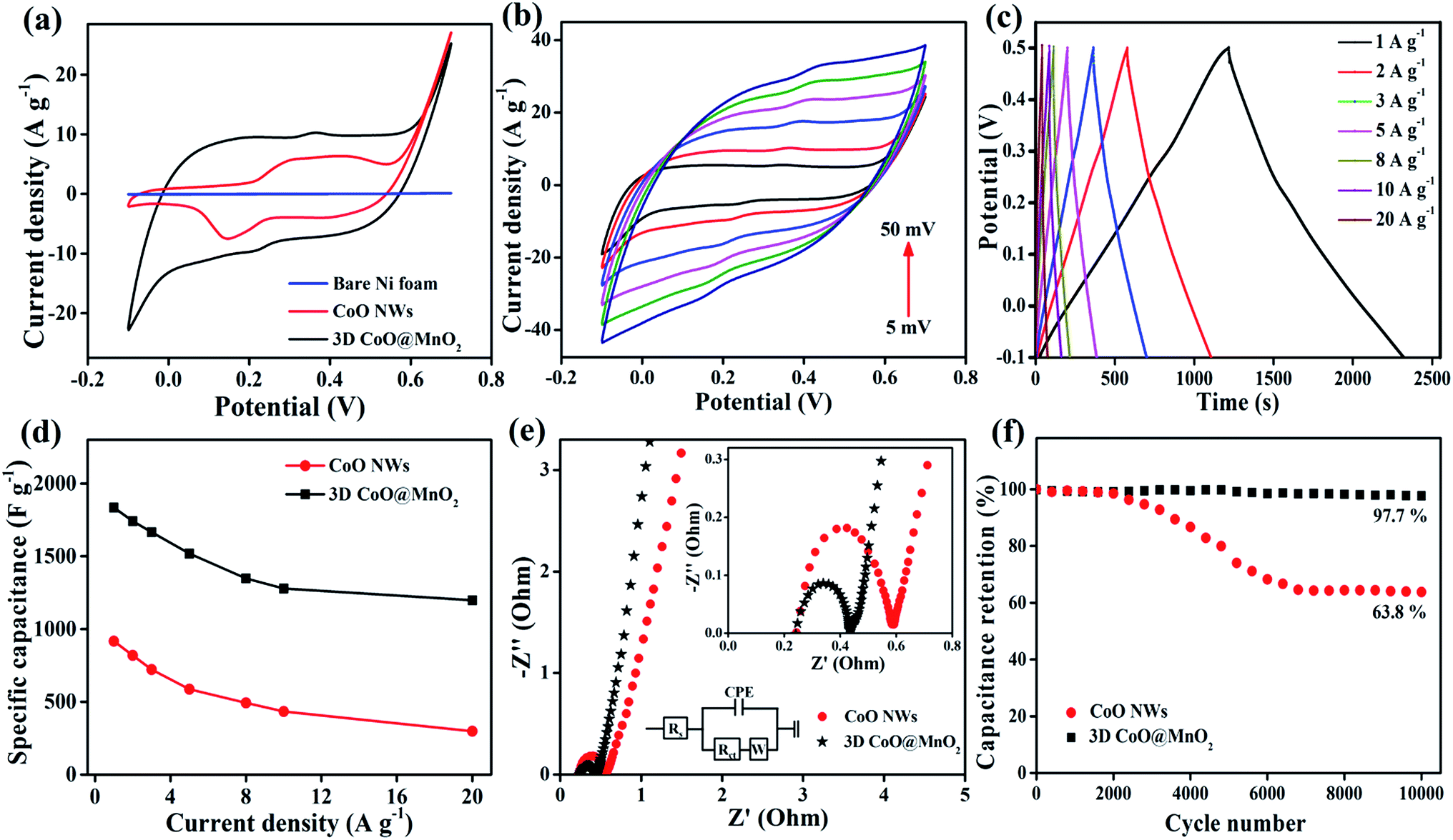 | ||
| Fig. 5 (a) CV curves of bare Ni foam, CoO NWs, and the 3D CoO@MnO2 core–shell nanohybrid at 10 mV s−1. (b) CV curves of the 3D CoO@MnO2 core–shell nanohybrid at different scan rates. (c) GCD curves of the 3D CoO@MnO2 core–shell nanohybrid at different current densities. (d) Specific capacitance vs. current density of the CoO NWs and the 3D CoO@MnO2 core–shell nanohybrid. (e) EIS spectra of CoO NWs and the 3D CoO@MnO2 core–shell nanohybrid (inset shows the enlarged area of the EIS spectra and the equivalent circuit diagram). (f) Cycle stabilities of the CoO NWs and 3D CoO@MnO2 core–shell nanohybrid as a function of the cycle number (the capacitance retention measurement was determined by GCD at a current density of 5 A g−1 for 10000 cycles). | ||
The electrochemical performance and rate capability of the 3D CoO@MnO2 core–shell nanohybrid were further investigated by GCD studies. The GCD characteristics of the 3D CoO@MnO2 core–shell nanohybrid at different current densities with a potential window of −0.1 to 0.5 V are shown in Fig. 5c. At discharge current densities of 1, 2, 3, 5, 8, 10, and 20 A g−1, the calculated specific capacitances of the 3D CoO@MnO2 core–shell nanohybrid are 1835, 1742, 1666, 1519, 1348, 1279, and 1198 F g−1, respectively. The GCD characteristics of CoO NWs are also shown in Fig. S7† for comparison. The calculated specific capacitance of CoO NWs are 917, 819, 722, 587, 493, 434, and 298 F g−1 at discharge current densities of 1, 2, 3, 5, 8, 10, and 20 A g−1, respectively. The GCD curves of the CoO NWs and 3D CoO@MnO2 core–shell nanohybrid at a current density of 1 A g−1 are shown in Fig. S8.† Impressively, the 3D CoO@MnO2 core–shell nanohybrid showed a maximum specific capacitance of 1835 F g−1 at 1 A g−1, which is superior to the capacitance performance of the as-prepared CoO NWs (917 F g−1 at 1 A g−1) and other cobalt-based nanohybrids (Table S1†). These excellent electrochemical properties are due to the exceptional properties of the hierarchical 3D CoO@MnO2 core–shell nanohybrid, including its high specific surface area, excellent conductivity, and extraordinary porosity. We also examine the relationship between the specific capacitances and current densities of the CoO NWs and the 3D CoO@MnO2 core–shell nanohybrid, as shown in Fig. 5d. These results show that the specific capacitance decreases as the current density increases. The hierarchical 3D CoO@MnO2 core–shell nanohybrid electrode shows an excellent rate capability, where 65.3% of its initial capacitance is sustained when the current density increases to 20 A g−1. The decrease in the specific capacitance at high current densities is due to the decrease in the effectiveness of the active material. The high specific capacitance may be due to the prodigious hierarchical 3D porous nanostructure features of the core–shell CoO@MnO2 as well as the synergistic interactions between CoO NWs (core) and the ultra-thin MnO2 nanosheet (shell) arrays.50–53 The CoO NWs encapsulated by MnO2 nanosheets can effectively improve the pseudocapacitive performance and form a unique porous architecture with an extraordinary active surface area. These features improve the electron transport properties in supercapacitor devices.
Here, the MnO2 nanosheet arrays not only prevent the CoO NWs from being exposed to the electrolyte solution during the GCD process, but they also improve the electrical conductivity and catalytic activity of the overall electrode material.54,55 Analyzing the EIS results is a basic method that can be used to observe the basic behaviour of energy storage devices. The EIS results of the as-prepared CoO NWs and 3D CoO@MnO2 core–shell nanohybrid are analyzed in the frequency range of 0.01–100 kHz, as illustrated in Fig. 5e. The EIS results revealed that the charge transfer resistance (Rct) of the 3D core–shell CoO@MnO2 was ∼0.32 Ω, which is lower than that of the as-prepared CoO NWs (0.41 Ω). The Nyquist plot of the 3D CoO@MnO2 core–shell nanohybrid on Ni foam exhibits a smaller semicircle in the high-frequency region. It also displays a vertical line in the low-frequency region, which indicates its fast electron transport properties. The EIS results further confirm that the binder-free, hierarchical 3D CoO@MnO2 core–shell nanohybrid has superior electrical conductivity and is a promising electrode material for high-performance energy storage devices. Additionally, the stability of the electrode materials is an essential requirement for practical energy storage devices. Thus, we also measured the long-term cycling stability of the as-prepared CoO NWs and 3D CoO@MnO2 core–shell nanohybrid by GCD analysis at a current density of 5 A g−1 for 10000 cycles (Fig. 5f). Remarkably, the specific capacitance of the 3D CoO@MnO2 core–shell nanohybrid electrode retains 97.7% of its original value, even after 10000 cycles; conversely, the specific capacitance of the CoO NWs only retains 63.8% of its original capacitance. This demonstrates the excellent cycling stability of the 3D CoO@MnO2 core–shell nanohybrid. The GCD curves obtained at a current density of 5 A g−1, both before and after 10000 cycles, were analyzed to confirm the outstanding cycling stability of the 3D CoO@MnO2 core–shell nanohybrid electrode (Fig. S9†). The GCD curves are still symmetric after cycling, indicating that no major structural changes occurred in the 3D CoO@MnO2 core–shell nanohybrid electrode during the GCD test. It is worth mentioning that the capacitance retention of the 3D CoO@MnO2 core–shell nanohybrid after the 10000th cycle is 97.7% (specific capacitance of 1519 F g−1 at the 1st cycle and 1484 F g−1 at the 10000th cycle). This value is significantly higher than that of the as-prepared CoO NWs (capacitance retention ∼ 63.8%). To the best of our knowledge, such outstanding capacitance retention has not been reported to date. Such long-term cycling stability is attributed to the coupling between the CoO NW core and the MnO2 shell in the nanohybrid. The MnO2 nanosheet arrays not only increase the surface area but also act as diffusion pathways for the transfer of electrolyte ions within the porous CoO NWs, thereby improving the energy storage properties of the nanohybrid. Thus, excellent coupling is achieved between the CoO NWs and thin MnO2 nanosheets in the nanohybrid. This coupling effect is beneficial for the electrocatalytic activity in supercapacitors. Furthermore, the EIS of the 3D CoO@MnO2 core–shell nanohybrid was measured before and after stability testing, as shown in Fig. S10.† The EIS curve was very similar before and after the stability test, indicating that no morphological defects were created in the 3D CoO@MnO2 core–shell nanohybrid. Therefore, due to its high specific capacitance and outstanding cycling stability, the 3D CoO@MnO2 core–shell nanohybrid can be used as a high-performance positive electrode material in supercapacitor applications. Additionally, to ensure the high capacitive performance of the 3D CoO@MnO2 core–shell nanohybrid, it is necessary to obtain a negative electrode material with a high capacitive performance.
These materials can be combined to design practical ASC devices with a wide potential window to yield a higher energy density than either of the components by themselves. When compared to activated carbon, as-prepared NG has superb electrical conductivity and specific surface area, which enhance the capacitive performance for practical energy device applications (as the negative potential electrode). The as-prepared NG was characterized by TEM and detailed discussions are provided in the ESI (Fig. S11†). We evaluated the capacitive performance of the as-prepared NG as a negative potential electrode. To do this, we used a basic CV study with the three-electrode system in the potential window of −1.0 to 0 V at different scan rates from 10 to 50 mV s−1 (Fig. S12†). The CV curves of the as-prepared NG maintained rectangular shapes up to higher scan rates without any changes, indicating the ideal capacitive behaviour and ultra-fast diffusion of K+ ions into the electrodes. The GCD curves of the NG were obtained at different current densities from 1 to 20 A g−1 and the potential window was maintained from −1.0 to 0 V. The specific capacitances of NG are 395, 376, 354, 320, 301, 291, and 282 at charge–discharge current densities of 1, 2, 3, 5, 8, 10, and 20 A g−1, respectively. The NG showed an ultra-high specific capacitance of 395 F g−1 at 1 A g−1. Even at a high current density of 20 A g−1, the specific capacitance of the NG was still 282 F g−1.
The specific capacitance vs. current density results based on the discharging curves are shown in Fig. S13.† Thus, the as-prepared NG is an excellent negative electrode that provides wonderful capacitive performance in supercapacitors. To further examine the practical energy storage of the devices consisting of the 3D CoO@MnO2 core–shell nanohybrid for supercapacitors, solid-state ASCs were designed by employing the 3D CoO@MnO2 core–shell nanohybrid as a positive electrode and the as-prepared NG as a negative electrode. CV studies of the as-prepared NG electrode were conducted between −1.0 and 0 V, demonstrating the characteristic features of an EDLC. Also, the 3D CoO@MnO2 core–shell nanohybrid electrode exhibited wonderful pseudocapacitive performance in the potential window of −0.1 to 0.7 V (Fig. S14†). The working potential window of ASCs can be extended because of their overpotential, which is related to the reversible hydrogen electrosorption in negative-potential, carbon-based electrode materials.56
In device experiments, 3D core–shell CoO@MnO2//NG ASCs were tested at different potential windows at a scan rate of 50 mV s−1 (Fig. 6a). When the operation potential window is increased up to 1.2 V, a triangular CV curve is observed, suggesting the incomplete pseudocapacitive character of the ASCs. When the operation potential window is increased to 1.4 V, oxidation and reduction peaks appear in the CV results, indicating the pseudocapacitive character. Furthermore, when increasing the operation potential window up to 1.8 V, separate redox peaks appear in the CV results. These correspond to strong redox reactions on the surface of the 3D CoO@MnO2 core–shell nanohybrid electrode. The GCD curves at different operating potential windows (from 0.8 to 1.8 V) with a current density of 2 A g−1 are shown in Fig. 6b. This study reveals that the fabricated ASCs display excellent capacitive performance with quasi-symmetrical triangular GCD characteristics, even at a high potential voltage window of 1.8 V. When the potential window increases from 0.8 to 1.8 V, the specific capacitance also increases from 88.4 to 179 F g−1; however, no obvious IR drop was observed in the GCD curves. It clearly reveals that an increase in the operating potential window from 0.8 to 1.8V causes a dramatic enhancement in the performance of supercapacitors.57,58
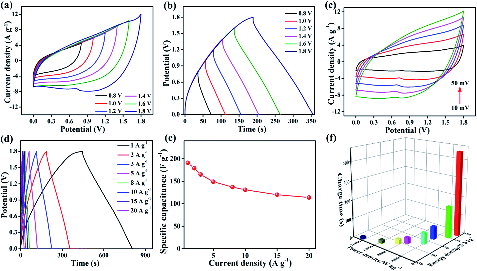 | ||
| Fig. 6 (a) CV curves (scan rate 50 mV s−1) of the optimized 3D core–shell CoO@MnO2//NG ASCs measured at different scan voltage windows, (b) GCD curves (at a current density of 2 A g−1) collected at different potential windows, (c) CV curves of 3D core–shell CoO@MnO2//NG ASCs at different scan rates (10−50 mV s−1), (d) GCD curves of 3D core–shell CoO@MnO2//NG ASCs at different current densities, (e) specific capacitance vs. current density of 3D core–shell CoO@MnO2//NG ASCs, and (f) Ragone plot (energy density vs. power density vs. charge time) of 3D core–shell CoO@MnO2//NG ASCs. | ||
This study confirms that an operation potential window of 1.8 V is optimal and leads to good capacitive performance in ASCs. The performance is also enhanced by using a KOH/PVA gel electrolyte. The CV curves of the optimized ASCs at various scan rates from 10 to 50 mV s−1 and potential windows from 0 to 1.8 V are presented in Fig. 6c. A combination of electrical double layers and pseudocapacitive characteristic peaks is observed, which are derived from the NG and 3D CoO@MnO2 core–shell nanohybrid, respectively. Similar characteristics were observed in all of the CV curves, even those taken at higher scan rates. The characteristic peaks of these CV curves are virtually the same, demonstrating the outstanding rate capability of the ASCs. The specific capacitance and rate capability of the 3D core–shell CoO@MnO2//NG ASCs were examined by GCD measurements. The GCD curves of the 3D core–shell CoO@MnO2//NG ASCs at different current densities (ranging from 1 to 20 A g−1) are shown in Fig. 6d. The 3D core–shell CoO@MnO2//NG ASCs exhibited a high specific capacitance of 191 F g−1 at a current density of 1 A g−1 (based on the total mass of the 3D CoO@MnO2 core–shell nanohybrid with NG). At a higher current density of 20 A g−1, the specific capacitance is only 114 F g−1. The 3D core–shell CoO@MnO2//NG ASC device demonstrates excellent rate capability with a capacitance retention of 59.7% at 20 A g−1.
The outstanding capacitive performance of our ASCs is related to the individual properties of the electrode materials and the high synergistic interactions between the 3D CoO@MnO2 core–shell nanohybrid (positive electrode) and NG (negative electrode). The 3D CoO@MnO2 core–shell nanohybrid (which demonstrates pseudocapacitive behaviour) as well as the as-prepared NG (which demonstrates electrical double layer behaviour) showed high specific capacitance values. The remarkable porous architecture of the 3D CoO@MnO2 core–shell nanohybrid and the high surface area of the as-prepared NG enhance the ion transport properties and reduce the length of ion and electron pathways significantly. This leads to an increase in the capacitive performance and rate capability of the ASCs. The relationship between the specific capacitance and the current density, based on the discharge curves, is shown in Fig. 6e. The specific capacitance of 3D core–shell CoO@MnO2//NG ASCs gradually decreased as the GCD current densities increased, which is attributed to the increase of the potential drop. The cycling performance of 3D core–shell CoO@MnO2//NG ASCs measured at a current density of 10 A g−1 up to 10000 cycles is shown in Fig. S15.† The specific capacitance retained 97.2% of its original value after 5000 cycles. Moreover, the total specific capacitance was reduced to just ∼86.8%, even after 10000 cycles, which reveals the outstanding cycle life of the ASCs. The stability performance of our ASCs is compared with devices found in the literature and illustrated in Table S2.† The EIS results of 3D core–shell CoO@MnO2//NG ASCs are shown in Fig. S16.† The Rct of the 3D core–shell CoO@MnO2//NG ASC device was calculated to be ∼1.57Ω. A slight increase in the Rct was observed (from ∼1.57 to ∼2.16 Ω) after 10000 cycles for this device. Therefore, the 3D CoO@MnO2 core–shell nanohybrid and as-prepared NG are superb electrode materials for designing ASC devices that can deliver high capacitive performance and long cycling stability.
Fig. 6f shows the Ragone plots (energy density vs. power density vs. charge time) for the 3D core–shell CoO@MnO2//NG ASC device. Most importantly, the 3D core–shell CoO@MnO2//NG ASCs demonstrate a maximum energy density of 85.9 W h kg−1 at a power density 852.4 W kg−1; the corresponding charge time is only ∼448 s. The energy density and power density results are compared with other ASCs found in the literature and are illustrated in Table S2.† Remarkably, the energy densities of the current fabricated ASCs are higher than those of similar types of reported materials, indicating that our device is useful for practical energy storage applications. Even at a high power density of 16769 W kg−1, our ASCs still reach an energy density of about ∼51.7 W h kg−1, clearly demonstrating their superior power capabilities. The high energy density and high power density of our ASCs, which also require a short charge time, should be useful for energy storage industries. The current 3D core–shell CoO@MnO2//NG ASCs demonstrate superior energy and power densities and a very short charge time, which make them quite promising for application in hybrid electric vehicles and modern electronics.
Conclusions
In summary, we have successfully developed a novel 3D CoO@MnO2 core–shell nanohybrid by using a facile two-step method. The 3D CoO@MnO2 core–shell nanohybrid, deposited on Ni foam, is directly evaluated as an advanced electrode material in a binder-free electrode for high-performance supercapacitors. The 3D CoO@MnO2 core–shell nanohybrid reveals higher specific capacitance (1835 F g−1 at a current density of 1 A g−1) and outstanding cycling stability (97.7% capacitance retention after 10000 cycles) when compared with other core–shell based nanohybrids. ASCs were fabricated using the hierarchical 3D CoO@MnO2 core–shell nanohybrid as the positive electrode and as-prepared NG as the negative electrode, and the practical energy storage of this device was investigated. The 3D core–shell CoO@MnO2//NG ASCs exhibit a high specific capacitance of 191 F g−1 at a current density of 1 A g−1, exceptional cycling stability in a wide potential window of 1.8 V (86.8% of its original capacitance after 10000 cycles), and also provide an excellent energy density of 85.9 W h kg−1 at a power density of 852.4 W kg−1. The greater electrochemical performance of the 3D core–shell CoO@MnO2//NG ASCs is likely related to the distinctive structural features of the 3D CoO@MnO2 core–shell nanohybrid electrode, such as its high surface area, hierarchical nanoarchitecture, extraordinary porosity, and highly assimilated electrode pattern. Due to the anticipated electrode configuration, cost-effective fabrication, and favorable electrochemical performance, this approach can be utilized to fabricate other novel nanostructured electrode materials that may be useful in a variety of energy storage and conversion device industries.
Acknowledgements
The work was supported by research funds for newly appointed professors of Chonbuk National University in 2015. It was also supported by the Basic Research program (2014R1A1A2056213) through the National Research Foundation (NRF) funded by the Ministry of Education and the Basic Research Laboratory Program (2014R1A4A1008140) through the Ministry of Science, ICT & Future Planning of Korea.Notes and references
- P. Simon and Y. Gogotsi, Nat. Mater., 2008, 7, 845–854 CrossRef CAS PubMed.
- H. Xia, C. Y. Hong, B. Li, B. Zhao, Z. X. Lin, M. B. Zheng, S. V. Savilov and S. M. Aldoshin, Adv. Funct. Mater., 2015, 25, 627–635 CrossRef CAS.
- L. F. Chen, Z. H. Huang, H. W. Liang, Q. F. Guan and S. H. Yu, Adv. Mater., 2013, 25, 4746–4752 CrossRef CAS PubMed.
- D. Shan, J. Yang, W. Liu, J. Yan and Z. Fan, J. Mater. Chem. A, 2016, 4, 13589–13602 CAS.
- X. Z. Yu, B. G. Lu and Z. Xu, Adv. Mater., 2014, 26, 1044–1051 CrossRef CAS PubMed.
- J. Balamurgan, G. Karthikeyan, T. D. Thanh, N. H. Kim and J. H. Lee, J. Power Sources, 2016, 308, 149–157 CrossRef.
- X. Wang, C. Yang and G. Wang, J. Mater. Chem. A, 2016, 4, 14839–14848 CAS.
- Y. Zhao, S. Huang, M. Xia, S. Rehman, S. Mu, Z. Kou, Z. Zhang, Z. Chen, F. Gao and Y. Hou, Nano Energy, 2016, 28, 346–355 CrossRef CAS.
- P. Wen, P. Gong, J. Sun, J. Wang and S. Yang, J. Mater. Chem. A, 2015, 3, 13874–13883 CAS.
- J. T. Zhang, J. W. Jiang, H. L. Li and X. S. Zhao, Energy Environ. Sci., 2011, 4, 4009–4015 CAS.
- C. R. Zhu, P. H. Yang, D. L. Chao, X. L. Wang, X. Zhang, S. Chen, B. K. Tay, H. Huang, H. Zhang, W. J. Mai and H. J. Fan, Adv. Mater., 2015, 27, 4566–4571 CrossRef CAS PubMed.
- F. M. Guo, R. Q. Xu, X. Cui, L. Zhang, K. L. Wang, Y. W. Yao and J. Q. Wei, J. Mater. Chem. A, 2016, 4, 9311–9318 CAS.
- M. Guo, J. Balamurugan, T. D. Thanh, N. H. Kim and J. H. Lee, J. Mater. Chem. A, 2016, 4, 17560–17571 CAS.
- S. G. Mohamed, C. J. Chen, C. K. Chen, S. F. Hu and R. S. Liu, ACS Appl. Mater. Interfaces, 2014, 6, 22701–22708 CAS.
- Q. L. Zhou, X. K. Ye, Z. Q. Wan and C. Y. Jia, J. Power Sources, 2015, 296, 186–196 CrossRef CAS.
- W. C. Jiang, D. S. Yu, Q. Zhang, K. L. Goh, L. Wei, Y. L. Yong, R. R. Jiang, J. Wei and Y. Chen, Adv. Funct. Mater., 2015, 25, 1063–1073 CrossRef CAS.
- Z. Q. Niu, W. Y. Zhou, X. D. Chen, J. Chen and S. S. Xie, Adv. Mater., 2015, 27, 6002–6008 CrossRef CAS PubMed.
- W. Q. Ma, H. H. Nan, Z. X. Gu, B. Y. Geng and X. J. Zhang, J. Mater. Chem. A, 2015, 3, 5442–5448 CAS.
- C. P. Fu, A. Mahadevegowda and P. S. Grant, J. Mater. Chem. A, 2016, 4, 2597–2604 CAS.
- H. N. Zhang, Y. J. Chen, W. W. Wang, G. H. Zhang, M. Zhuo, H. M. Zhang, T. Yang, Q. H. Li and T. H. Wang, J. Mater. Chem. A, 2013, 1, 8593–8600 CAS.
- Y. M. He, W. J. Chen, X. D. Li, Z. X. Zhang, J. C. Fu, C. H. Zhao and E. Q. Xie, ACS Nano, 2013, 7, 174–182 CrossRef CAS PubMed.
- Z. P. Li, Y. J. Mi, X. H. Liu, S. Liu, S. R. Yang and J. Q. Wang, J. Mater. Chem., 2011, 21, 14706–14711 RSC.
- W. F. Wei, X. W. Cui, W. X. Chen and D. G. Ivey, Chem. Soc. Rev., 2011, 40, 1697–1721 RSC.
- J. Balamurugan, R. Thangamuthu and A. Pandurangan, J. Mater. Chem. A, 2013, 1, 5070–5080 CAS.
- Z. J. Fan, J. Yan, L. J. Zhi, Q. Zhang, T. Wei, J. Feng, M. L. Zhang, W. Z. Qian and F. Wei, Adv. Mater., 2010, 22, 3723–3728 CrossRef CAS PubMed.
- C. G. Liu, Z. N. Yu, D. Neff, A. Zhamu and B. Z. Jang, Nano Lett., 2010, 10, 4863–4868 CrossRef CAS PubMed.
- J. Balamurugan, T. D. Thanh, N. H. Kim and J. H. Lee, Adv. Mater. Interfaces, 2016, 3, 1500348 CrossRef.
- P. Chen, J. J. Yang, S. S. Li, Z. Wang, T. Y. Xiao, Y. H. Qian and S. H. Yu, Nano Energy, 2013, 2, 249–256 CrossRef CAS.
- J. Cherusseri and K. K. Kar, J. Mater. Chem. A, 2016, 4, 9910–9922 CAS.
- F. Grote and Y. Lei, Nano Energy, 2014, 10, 63–70 CrossRef CAS.
- J. P. Liu, J. Jiang, C. W. Cheng, H. X. Li, J. X. Zhang, H. Gong and H. J. Fan, Adv. Mater., 2011, 23, 2076–2081 CrossRef CAS PubMed.
- D. Z. Kong, J. S. Luo, Y. L. Wang, W. N. Ren, T. Yu, Y. S. Luo, Y. P. Yang and C. W. Cheng, Adv. Funct. Mater., 2014, 24, 3815–3826 CrossRef CAS.
- J. C. Deng, L. T. Kang, G. L. Bai, Y. Li, P. Y. Li, X. G. Liu, Y. Z. Yang, F. Gao and W. Liang, Electrochim. Acta, 2014, 132, 127–135 CrossRef CAS.
- Q. S. Song, G. K. Aravindaraj, H. Sultana and S. L. I. Chan, Electrochim. Acta, 2007, 53, 1890–1896 CrossRef CAS.
- J. Balamurugan, T. D. Thanh, N. H. Kim and J. H. Lee, J. Mater. Chem. A, 2016, 4, 9555–9565 CAS.
- S. Roldan, D. Barreda, M. Granda, R. Menendez, R. Santamaria and C. Blanco, Phys. Chem. Chem. Phys., 2015, 17, 1084–1092 RSC.
- X. H. Xia, J. P. Tu, Y. Q. Zhang, J. Chen, X. L. Wang, C. D. Gu, C. Guan, J. S. Luo and H. J. Fan, Chem. Mater., 2012, 24, 3793–3799 CrossRef CAS.
- C. X. Peng, B. D. Chen, Y. Qin, S. H. Yang, C. Z. Li, Y. H. Zuo, S. Y. Liu and J. H. Yang, ACS Nano, 2012, 6, 1074–1081 CrossRef CAS PubMed.
- P. H. Yang, X. Xiao, Y. Z. Li, Y. Ding, P. F. Qiang, X. H. Tan, W. J. Mai, Z. Y. Lin, W. Z. Wu, T. Q. Li, H. Y. Jin, P. Y. Liu, J. Zhou, C. P. Wong and Z. L. Wang, ACS Nano, 2013, 7, 2617–2626 CrossRef CAS PubMed.
- Y. S. Luo, J. Jiang, W. W. Zhou, H. P. Yang, J. S. Luo, X. Y. Qi, H. Zhang, D. Y. W. Yu, C. M. Li and T. Yu, J. Mater. Chem., 2012, 22, 8634–8640 RSC.
- C. Zhou, Y. W. Zhang, Y. Y. Li and J. P. Liu, Nano Lett., 2013, 13, 2078–2085 CrossRef CAS PubMed.
- C. Guan, J. P. Liu, C. W. Cheng, H. X. Li, X. L. Li, W. W. Zhou, H. Zhang and H. J. Fan, Energy Environ. Sci., 2011, 4, 4496–4499 CAS.
- K. W. Qiu, Y. Lu, D. Y. Zhang, J. B. Cheng, H. L. Yan, J. Y. Xu, X. M. Liu, J. K. Kim and Y. S. Luo, Nano Energy, 2015, 11, 687–696 CrossRef CAS.
- J. Chen, X. H. Xia, J. P. Tu, Q. Q. Xiong, Y. X. Yu, X. L. Wang and C. D. Gu, J. Mater. Chem., 2012, 22, 15056–15061 RSC.
- J. Zhao, J. Chen, S. Xu, M. Shao, Q. Zhang, F. Wei, J. Ma, M. Wei, D. G. Evans and X. Duan, Adv. Funct. Mater., 2014, 24, 2938–2946 CrossRef CAS.
- K. Z. Cao, L. F. Jiao, Y. C. Liu, H. Q. Liu, Y. J. Wang and H. T. Yuan, Adv. Funct. Mater., 2015, 25, 1082–1089 CrossRef CAS.
- J. H. Shi, X. C. Li, G. H. He, L. Zhang and M. Li, J. Mater. Chem. A, 2015, 3, 20619–20626 CAS.
- Y. B. He, G. R. Li, Z. L. Wang, C. Y. Su and Y. X. Tong, Energy Environ. Sci., 2011, 4, 1288–1292 CAS.
- S. H. Cho, K. H. Shin and J. S. Jang, ACS Appl. Mater. Interfaces, 2013, 5, 9186–9193 CAS.
- Y. Zhao, W. Ran, J. He, Y. Huang, Z. Liu, W. Liu, Y. Tang, L. Zhang, D. Gao and F. Gao, Small, 2015, 11, 1310–1319 CrossRef CAS PubMed.
- H. Ma, J. He, D. B. Xiong, J. Wu, Q. Li, V. Dravid and Y. Zhao, ACS Appl. Mater. Interfaces, 2016, 8, 1992–2000 CAS.
- Y. Zhao, Z. Zhang, Y. Ren, W. Ran, X. Chen, J. Wu and F. Gao, J. Power Sources, 2015, 286, 1–9 CrossRef CAS.
- Z. Chen, D. B. Xiong, X. Zhang, H. Ma, M. Xia and Y. Zhao, Nanoscale, 2016, 8, 6636–6645 RSC.
- Y. W. Cheng, S. T. Lu, H. B. Zhang, C. V. Varanasi and J. Liu, Nano Lett., 2012, 12, 4206–4211 CrossRef CAS PubMed.
- J. Balamurugan, T. D. Thanh, S. B. Heo, N. H. Kim and J. H. Lee, Carbon, 2015, 94, 962–970 CrossRef CAS.
- K. Fic, E. Frackowiak and F. Beguin, J. Mater. Chem., 2012, 22, 24213–24223 RSC.
- F. Luan, G. M. Wang, Y. C. Ling, X. H. Lu, H. Y. Wang, Y. X. Tong, X. X. Liu and Y. Li, Nanoscale, 2013, 5, 7984–7990 RSC.
- B. Wang, J. S. Chen, Z. Y. Wang, S. Madhavi and X. W. Lou, Adv. Energy Mater., 2012, 2, 1188–1192 CrossRef CAS.
Footnote |
| † Electronic supplementary information (ESI) available: FE-SEM, EDAX, STEM, EDS colour mapping, CV, GCD, EIS studies, and energy density comparison table. See DOI: 10.1039/c6ta08532f |
| This journal is © The Royal Society of Chemistry 2017 |