 Open Access Article
Creative Commons Attribution 3.0 Unported Licence
Swimming with a cage: low-Reynolds-number locomotion inside a droplet
Shang Yik
Reigh†
 *ab,
Lailai
Zhu†‡§
 *c,
François
Gallaire
*c and
Eric
Lauga
 *a
*a
aDepartment of Applied Mathematics and Theoretical Physics, Center for Mathematical Science, University of Cambridge, Wilberforce Road, Cambridge CB3 0WA, UK. E-mail: e.lauga@damtp.cam.ac.uk
bMax-Plank-Institut für Intelligente Systeme, Heisenbergstraße 3, 70569 Stuttgart, Germany. E-mail: reigh@is.mpg.de
cLaboratory of Fluid Mechanics and Instabilities, Ecole Polytechnique Fédérale de Lausanne, Lausanne, CH-1015, Switzerland. E-mail: lailaizhu00@gmail.com; francois.gallaire@epfl.ch
First published on 10th March 2017
Abstract
Inspired by recent experiments using synthetic microswimmers to manipulate droplets, we investigate the low-Reynolds-number locomotion of a model swimmer (a spherical squirmer) encapsulated inside a droplet of a comparable size in another viscous fluid. Meditated solely by hydrodynamic interactions, the encaged swimmer is seen to be able to propel the droplet, and in some situations both remain in a stable co-swimming state. The problem is tackled using both an exact analytical theory and a numerical implementation based on a boundary element method, with a particular focus on the kinematics of the co-moving swimmer and the droplet in a concentric configuration, and we obtain excellent quantitative agreement between the two. The droplet always moves slower than a swimmer which uses purely tangential surface actuation but when it uses a particular combination of tangential and normal actuations, the squirmer and droplet are able to attain the same velocity and stay concentric for all times. We next employ numerical simulations to examine the stability of their concentric co-movement, and highlight several stability scenarios depending on the particular gait adopted by the swimmer. Furthermore, we show that the droplet reverses the nature of the far-field flow induced by the swimmer: a droplet cage turns a pusher swimmer into a puller, and vice versa. Our work sheds light on the potential development of droplets as self-contained carriers of both chemical content and self-propelled devices for controllable and precise drug deliveries.
1 Introduction
Droplets have recently been used as small, isolated, aqueous compartments to encapsulate, incubate and manipulate cells for biological assays.1 Such droplet-based cell encapsulation is commonly accomplished in microfluidic devices which are able to precisely produce and manipulate microdroplets of adjustable sizes.2,3 Current microfluidic technology allows a high-throughput and controllable analysis to be performed on individual cells in their own discrete microenvironments.In related work, droplets have been used to cage motile organisms such as the nematode Caenorhabditis elegans (C. elegans)4,5 in order to carry out developmental work. In these studies, the size of an encaged adult C. elegans is comparable to the droplet radius. Despite their mobility, the worms failed to propel their liquid cages, because they were immobilized. In the work of ref. 4, the droplet was tightly squeezed inside a capillary tube, forming a plug thus immobilized hydrodynamically by the lubrication film while in the work of ref. 5, the droplet was anchored mechanically by a microfluidic trap.
Motivated by these droplet-based encapsulations of motile organisms, we raise in this paper a simple question: is it possible for a microswimmer encaged in a droplet to propel its viscous cage and co-swim with it? One could envision setups of this type of interest to the drug delivery community using droplets as small self-contained units propelled and steered by their internal synthetic swimmers.
Recently, microrobots propelled by a magnetically-rotated helical appendage mimicking the flagella of bacteria such as Escherichia coli (E. coli) were fabricated,6,7 encapsulated and operated inside a water-in-oil droplet in microfluidic chips.8 In this case, the droplets were not mobile, presumably for two reasons: the swimmer was much smaller than the droplet and the droplet was large compared to the height of the micro-fluidic chips so that it was tightly squeezed and thus anchored hydrodynamically.4 Excitingly, the same group managed however to use their microrobots to push a droplet of a comparable size from the exterior when the droplet was unbounded or loosely bounded. From the theoretical point of view, the locomotion of a droplet driven by the internal release of a surfactant was previously considered.9
In this paper, we conduct a combined theoretical and numerical study of a three-dimensional (3D) model microswimmer encapsulated in a droplet in free space. The size of the swimmer is of the same order as the radius of the droplet and we attempt to answer the following fundamental questions: will the droplet co-swim with the swimmer? What is the swimming velocity of the droplet compared to that of the swimmer? How are the kinematics and energetics of the microswimmer affected by the confinement due to the presence of the droplet? How stable is the co-movement of the concentric pair of the swimmer and droplet?
2 Problem description
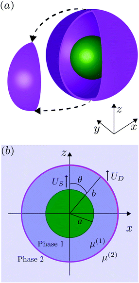
We consider, in the creeping-flow regime, the locomotion of a 3D microswimmer encapsulated in a droplet. Due to hydrodynamic interactions, the motion of the swimmer is influenced by the presence of the droplet interface. The geometrical setup is shown in Fig. 1a. We use a spherical, axisymmetric squirmer10,11 as our model swimmer. It achieves locomotion by squirming, i.e. by generating tangential and/or normal velocities on its fixed spherical surface. This is a classical model for physical actuation of microorganisms continuously deforming their bodies or beating their densely-packed cilia, and has been employed in the past to address a variety of biophysical aspects of locomotion.12–19 The shape of the droplet is maintained as spherical by maintaining a sufficiently large surface tension γ on its interface, i.e. we assume to remain in the low-Capillary number limit. The radius of the squirmer is denoted by a while that of the droplet is b > a, respectively, and χ = b/a > 1 is the size ratio. The fluid phases inside and outside the droplet are marked as phase 1 and 2. Both are Newtonian, with dynamic viscosities of μ(1) and μ(2), and λ = μ(2)/μ(1) denotes the viscosity ratio. Both Cartesian (x,y,z) and spherical (r,θ,ϕ) coordinate systems are used, shown in Fig. 1b.We then solve the steady Stokes equations for fluid phase 1 and 2,
| ∇p(i) = μ(i)∇2v(i), ∇·v(i) = 0, | (1) |
In the laboratory frame of reference, the fluid velocity components v(1) = (v(1)r,v(1)θ) on the swimmer surface, r = a, are given by
 | (2) |
![[thin space (1/6-em)]](https://www.rsc.org/images/entities/char_2009.gif) θ, Vn = − 2P1n(ξ)/(n2 + n), and P1n is the associated Legendre function of the first kind of order 1. In eqn (2), US is the value of the unknown swimming velocity of the swimmer, and UD is the unknown swimming speed of the droplet.
θ, Vn = − 2P1n(ξ)/(n2 + n), and P1n is the associated Legendre function of the first kind of order 1. In eqn (2), US is the value of the unknown swimming velocity of the swimmer, and UD is the unknown swimming speed of the droplet.
On the droplet interface r = b, the normal velocities in the droplet frame vanish because the droplet does not deform. In addition, the tangential velocities and tangential stresses are continuous across the interface. These boundary conditions formulated in the laboratory frame are written as
 | (3) |
Finally, the total hydrodynamic forces exerted on both the swimmer and on the droplet interface are zero, which will be used to determine the values of both swimming velocities, US and UD. For an unbounded squirmer in a single-phase fluid, the velocity US ≡ UD is given by10,11
 | (4) |
3 Analytical theory
We first solve the problem analytically. The methodology is based on Lamb's general solution of the Stokes equations in spherical coordinates.20,21 For a single-phase fluid with viscosity μ, the fluid velocity field v can be expanded in spherical harmonics as | (5) |
pn(r,ξ) = ![[p with combining tilde]](https://www.rsc.org/images/entities/i_char_0070_0303.gif) nrnPn(ξ), ϕn(r,ξ) = nrnPn(ξ), ϕn(r,ξ) = ![[small phi, Greek, tilde]](https://www.rsc.org/images/entities/i_char_e0e2.gif) nrnPn(ξ), nrnPn(ξ), |
![[p with combining tilde]](https://www.rsc.org/images/entities/i_char_0070_0303.gif) n and
n and ![[small phi, Greek, tilde]](https://www.rsc.org/images/entities/i_char_e0e2.gif) n are constants independent of r and ξ.
n are constants independent of r and ξ.
The radial and tangential velocity components vr and vθ are then obtained as
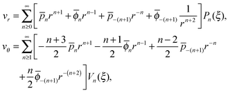 | (6) |
Note that the solution for the flow in region 1 may contain all terms in the brackets of eqn (6) while those in region 2 only contain the last two terms due to the boundary condition at infinity.
Applying this framework to our case, we use eqn (6) for both the inner and outer fluid, solving for the unknown constants ![[p with combining macron]](https://www.rsc.org/images/entities/i_char_0070_0304.gif) (i)n,
(i)n, ![[small phi, Greek, macron]](https://www.rsc.org/images/entities/i_char_e0d6.gif) (i)n,
(i)n, ![[p with combining macron]](https://www.rsc.org/images/entities/i_char_0070_0304.gif) (i)−(n+1) and
(i)−(n+1) and ![[small phi, Greek, macron]](https://www.rsc.org/images/entities/i_char_e0d6.gif) (i)−(n+1) (i = 1, 2) using the boundary conditions, eqn (2) and (3), together with the condition at infinity. Taking the n = 0, 1 terms in the series expansion of eqn (6) with the use of eqn (2) and (3) leads to the system for the inner fluid
(i)−(n+1) (i = 1, 2) using the boundary conditions, eqn (2) and (3), together with the condition at infinity. Taking the n = 0, 1 terms in the series expansion of eqn (6) with the use of eqn (2) and (3) leads to the system for the inner fluid
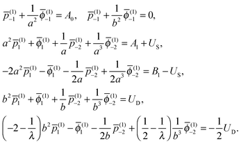 | (7) |
![[p with combining macron]](https://www.rsc.org/images/entities/i_char_0070_0304.gif) (1)n and
(1)n and ![[small phi, Greek, macron]](https://www.rsc.org/images/entities/i_char_e0d6.gif) (1)n (n = −2, −1 and 1) are obtained explicitly in terms of both US and UD. The constants in the outer fluid are then given by
(1)n (n = −2, −1 and 1) are obtained explicitly in terms of both US and UD. The constants in the outer fluid are then given by | (8) |
![[p with combining macron]](https://www.rsc.org/images/entities/i_char_0070_0304.gif) (2)−1 = 0 and
(2)−1 = 0 and ![[small phi, Greek, macron]](https://www.rsc.org/images/entities/i_char_e0d6.gif) (2)−1 = 0.
(2)−1 = 0.
Applying the force-free condition for the swimmer, we have
 | (9) |
![[p with combining macron]](https://www.rsc.org/images/entities/i_char_0070_0304.gif) (1)−2 = 0. Applying the same condition for the droplet, we obtain
(1)−2 = 0. Applying the same condition for the droplet, we obtain ![[p with combining macron]](https://www.rsc.org/images/entities/i_char_0070_0304.gif) (2)−2 = 0. Plugging the two constants into eqn (7), we obtain the values of all underdetermined constants together with the velocity of the swimmer, US, and that of the droplet, UD, as,
(2)−2 = 0. Plugging the two constants into eqn (7), we obtain the values of all underdetermined constants together with the velocity of the swimmer, US, and that of the droplet, UD, as, | (10) |
 | (11) |
 | (12) |
In order to complete the calculation and characterize the flow in both fluids, we need to calculate the values of the constants ![[p with combining macron]](https://www.rsc.org/images/entities/i_char_0070_0304.gif) n,
n, ![[small phi, Greek, macron]](https://www.rsc.org/images/entities/i_char_e0d6.gif) n,
n, ![[p with combining macron]](https://www.rsc.org/images/entities/i_char_0070_0304.gif) −(n+1) and
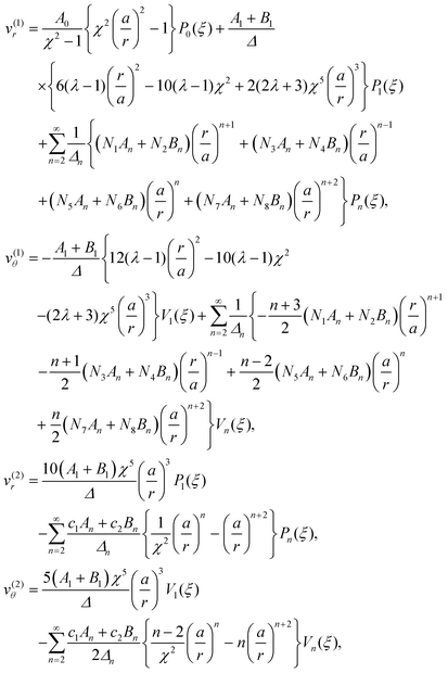
−(n+1) and ![[small phi, Greek, macron]](https://www.rsc.org/images/entities/i_char_e0d6.gif) −(n+1) for n ≥ 2 in the series expansion from eqn (6). The velocities inside and outside the droplet in the laboratory frame are then obtained to be
−(n+1) for n ≥ 2 in the series expansion from eqn (6). The velocities inside and outside the droplet in the laboratory frame are then obtained to be
 | (13) |
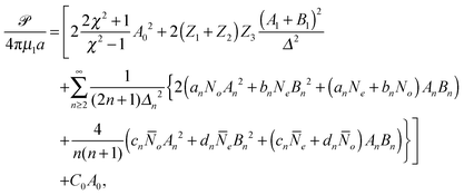
We can finally calculate the power consumption of the squirmer, ![[scr P, script letter P]](https://www.rsc.org/images/entities/char_e52f.gif) , which is equal to the rate of work done by the squirmer on the fluid,
, which is equal to the rate of work done by the squirmer on the fluid,
 | (14) |
 | (15) |
4 Numerical simulations
In parallel with our theoretical approach, we use numerical simulations based on a 3D boundary element method. By choosing the characteristic length, velocity, and stress as b, λγ/{μ(2)(1 + λ)}, and γ/b respectively, the nondimensional boundary integral formulation for the matching-viscosity case (λ = 1) can be obtained. The nondimensional velocity u(x0) at position x0 everywhere in the domain is classically written as | (16) |
![[S with combining tilde]](https://www.rsc.org/images/entities/i_char_0053_0303.gif) and Ŝ denote the surface of the droplet and swimmer respectively, n the normal vector on
and Ŝ denote the surface of the droplet and swimmer respectively, n the normal vector on ![[S with combining tilde]](https://www.rsc.org/images/entities/i_char_0053_0303.gif) towards the outer fluid,
towards the outer fluid,  the mean curvature of
 ![[S with combining tilde]](https://www.rsc.org/images/entities/i_char_0053_0303.gif) , and q the density of the single-layer potential on Ŝ. The tensor G is the free-space Green's function, also known as the Stokeslet or the Oseen–Burgers tensor,
, and q the density of the single-layer potential on Ŝ. The tensor G is the free-space Green's function, also known as the Stokeslet or the Oseen–Burgers tensor, | (17) |
The surfaces of the swimmer and droplet are discretized using zero-order flat quadrilateral and second-order curved triangular elements respectively. For the spherical swimmer, a six-patch structured mesh23,24 consisting of 600 (before mesh refinement) elements is constructed. The number of elements on the droplet interface is around 2500 (∼5000 discretized points). Gauss–Legendre quadrature is applied on the quadrilateral elements to compute nonsingular integrations; on triangular elements, we compute the integrations using a symmetric Gaussian quadrature rule.25 When x0 is on the surfaces ![[S with combining tilde]](https://www.rsc.org/images/entities/i_char_0053_0303.gif) or Ŝ, the surface integrals become singular and different desingularization strategies are chosen: on the droplet interface
or Ŝ, the surface integrals become singular and different desingularization strategies are chosen: on the droplet interface ![[S with combining tilde]](https://www.rsc.org/images/entities/i_char_0053_0303.gif) , the well-known integral identity for G is exploited and hence the first integral in eqn (16) becomes
, the well-known integral identity for G is exploited and hence the first integral in eqn (16) becomes
 | (18) |
![[scr O, script letter O]](https://www.rsc.org/images/entities/char_e52e.gif) (r−1) singularity of the original integrand is removed; on the squirmer surface
(r−1) singularity of the original integrand is removed; on the squirmer surface ![[S with combining tilde]](https://www.rsc.org/images/entities/i_char_0053_0303.gif) , each quadrilateral element is divided into four triangular sub-elements, where the transformation of polar coordinates26 with Gauss–Legendre quadrature is adopted to desingularize the integral. Both integrals in eqn (16) tend to be nearly singular when the distance between the two surfaces
, each quadrilateral element is divided into four triangular sub-elements, where the transformation of polar coordinates26 with Gauss–Legendre quadrature is adopted to desingularize the integral. Both integrals in eqn (16) tend to be nearly singular when the distance between the two surfaces ![[S with combining tilde]](https://www.rsc.org/images/entities/i_char_0053_0303.gif) and Ŝ is too small. Desingularizing measures are hence taken for them: on the droplet interface
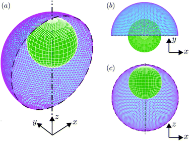
and Ŝ is too small. Desingularizing measures are hence taken for them: on the droplet interface ![[S with combining tilde]](https://www.rsc.org/images/entities/i_char_0053_0303.gif) , a high-order near-singularity subtraction is implemented by following ref. 27 and on the swimmer surface Ŝ, adaptive mesh refinement is utilized. Fig. 2 presents a schematic view of the adaptively-refined mesh.
, a high-order near-singularity subtraction is implemented by following ref. 27 and on the swimmer surface Ŝ, adaptive mesh refinement is utilized. Fig. 2 presents a schematic view of the adaptively-refined mesh.
A crucial numerical difficulty arising from droplet/bubble simulations based on Lagrangian interface representation is to maintain the quality of the mesh of the interface. In order to guarantee the smoothness and orthogonality of the triangle mesh over a long time evolution, we implement a so-called ‘passive mesh stabilization’ scheme.28,29 At each time step, the scheme searches the optimal tangential field that is added to the normal velocity to update the Lagrangian points, minimizing a global kinetic-energy-like norm that quantifies the clustering and distortion of the mesh. This scheme significantly slows down mesh degradation. Its effectiveness was proved in the previous study on a squeezed pancake droplet in a microfluidic chip based on an accelerated boundary integral implementation.30
In contrast to the infinite-surface tension assumed in the theory, a large but finite surface tension is adopted in the simulations and hence the numerical droplet is not strictly spherical but slightly deformable. The strength of the typical ratio of viscous stresses to surface tension forces is measured by the capillary number, Ca ≡ μ(2)B1/γ, and Ca = 0 corresponds to the theoretical limit of infinite surface tension. We vary Ca numerically from 10−3 to 10−2, without detecting significant changes in the kinematics of the swimmer. We hence use Ca = 10−3 throughout our study, and are able to approximate well the Ca = 0 limit from our a posteriori comparison with the theory.
5 Results
5.1 Squirming with purely tangential velocities
In this section, we start by investigating the instantaneous dynamics of a droplet encapsulating a squirmer using solely tangential surface velocities, i.e. with An = 0. If one further sets the Bn (n ≥ 3) modes to zero, as is classically done for the squirmer model,13 the swimming gait consists of only B1 and B2 modes: the B1 mode determines the swimming velocity while the B2 mode captures the leading order disturbance flow induced by the swimmer, namely a stresslet (or force dipole). We define β ≡ B2/B1 to measure the relative strength of the stresslet. The squirmer is said to be neutral when β = 0, while it is a pusher (respectively a puller) when β is negative (respectively positive). Varying the value of β allows modeling the majority of swimming microorganisms and synthetic microswimmers: pushers model flagellated bacteria such as E. coli31 while biflagellated green algae such as C. reinhardtii32–34 are pullers. Neutral swimmers may be considered as special cases of synthetic swimmers such as Janus particles self-propelling owing to various phoretic mechanisms or some active droplets driven by Marangoni stresses.35–42 | (19) |
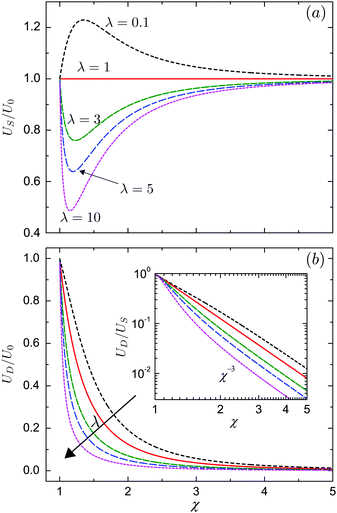
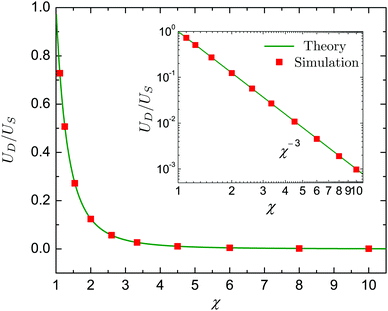
We plot in Fig. 3a the dependence of the swimmer velocity on χ and λ. The velocity decreases monotonically with λ. When the outer and inner phase have matching viscosities (λ = 1), US is not affected by the presence of the droplet, and is thus equal to the unbounded velocity U0 for all values of χ. The squirmer swims faster than the unbounded one when the outer phase is less viscous than the inner (λ < 1), and swims slower in the opposite limit, λ > 1. When λ ≠ 1, the velocity US varies with the size ratio χ non-monotonically, reaching its maximum value for λ < 1 when the swimmer is tightly confined, χ ≈ 1.1–1.2, namely when the droplet is slightly larger than the swimmer. The result is similar when λ > 1 and the minimum is reached. For any viscosity ratios, US = U0 in the limit of χ = 1 and χ → ∞. The former corresponds to the situation when the droplet exactly encompasses the swimmer and the latter to when the droplet is much larger than the swimmer. In Fig. 3b, we further show that the velocity of the droplet decreases monotonically with χ, as well as with λ. The inset of Fig. 3b presents the ratio UD/US of the droplet velocity over the swimmer velocity as a function of χ in a log–log form, this ratio decays as χ−3 for large χ. It is important to note that for any values of χ or λ the swimmer is always faster than the droplet, US > UD. The concentric configuration is thus not a steady state if the swimmer only applies tangential forcing.
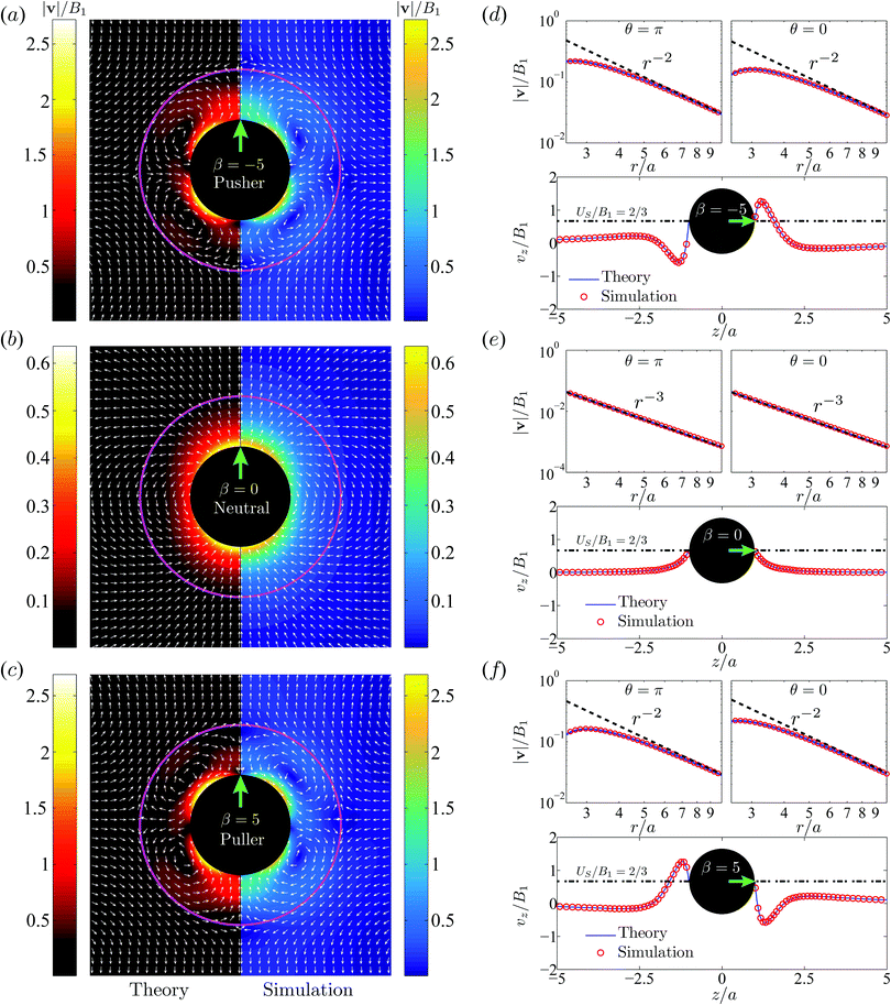
Next in Fig. 5a–c, we plot the flow velocity field, v/B1, in the laboratory frame for the pusher (a), neutral (b) and puller (c) swimmers respectively. The size ratio is χ = 2. Theoretical results are shown on the left panel and numerical data on the right. The numerical predictions show good agreement with the theoretical data in most of the flow domain except very close to the droplet interface where numerical errors arise from the nearly-singular integration.
For the neutral swimmer, note that the velocity field is not affected at all by the presence of the droplet. This is corroborated by the fact that neither the swimming velocity nor the power are impacted by the droplet, as implied by eqn (10) and (15). This results from the vanishing radial velocity in the droplet frame, such that the spherical droplet interface introduces no perturbation and hence does not influence the swimming dynamics.
For the pusher in a drop, similar to a pusher in free space, fluid is locally pushed away from the anterior (θ = 0) and posterior (θ = π) parts of the swimmer and comes to the lateral directions (θ = π/2). Due to the non-penetrating nature of the droplet interface, two counter-rotating toroidal vortices form inside. Outside the droplet the fluid is drawn towards its poles and expelled away on the equatorial plane. Interestingly the flow signature of a local pusher turns therefore into a puller in a far field. More quantitatively one can show that the velocity fields of a puller with β > 0 and a pusher with −β satisfy the relation
| vr|β(r,π − θ) + vr|−β(r,θ) = 0, |
| vθ|β(r,π − θ) − vθ|−β(r,θ) = 0, | (20) |
We next investigate the spatial variation of v(z)/B1 along the z axis in Fig. 5d–f, for the three swimmers. Here again, numerical data (empty red circles) agree very well with the theoretical predictions (solid blue line). The velocity magnitude, |v|/B1, decays in the far-field from the swimmer center as r−2 for the pusher/puller and r−3 for the neutral swimmer. The velocity distribution v(z) over z for the pusher and that for the puller are symmetric about z = 0, as implied by eqn (20). For both swimmers, two stagnation points appear near the droplet interface r = b, one close to the frontal interface and the other close to the rear. They can be observed in Fig. 5.
It is worth emphasizing the result that the presence of a droplet reverses the direction of the far-field flow with respect to that of a pusher/puller in free space (Fig. 5a and c). This can be made more precise by an analysis of the theoretical predictions in eqn (13). With only B1 and B2 modes, the leading-order contribution to the radial velocity v(2)r in the outer phase is
 | (21) |
 | (22) |
![[scr P, script letter P]](https://www.rsc.org/images/entities/char_e52f.gif) based on eqn (15) is simplified to
based on eqn (15) is simplified to | (23) |
![[d with combining macron]](https://www.rsc.org/images/entities/i_char_0064_0304.gif) n = 4χ2n+3 − (2n + 3)χ4 + (2n − 1), n = 4χ2n+3 − (2n + 3)χ4 + (2n − 1), |
![[capital Delta, Greek, macron]](https://www.rsc.org/images/entities/i_char_e135.gif) n = 8χ2n+3 − (2n + 1)(2n + 3)χ4 + 2(2n − 1)(2n + 3)χ2 − (2n − 1)(2n + 1). n = 8χ2n+3 − (2n + 1)(2n + 3)χ4 + 2(2n − 1)(2n + 3)χ2 − (2n − 1)(2n + 1). | (24) |
Restricting then our attention to the simplest squirmer with Bn = 0 for n ≥ 3, the power becomes
 | (25) |
 | (26) |
Theoretical and numerical values of ![[scr P, script letter P]](https://www.rsc.org/images/entities/char_e52f.gif) show excellent agreement, as shown in Fig. 6. The power of an encapsulated squirmer,
show excellent agreement, as shown in Fig. 6. The power of an encapsulated squirmer, ![[scr P, script letter P]](https://www.rsc.org/images/entities/char_e52f.gif) , always exceeds that of an unbounded one,
, always exceeds that of an unbounded one, ![[scr P, script letter P]](https://www.rsc.org/images/entities/char_e52f.gif) 0. From a practical standpoint,
0. From a practical standpoint, ![[scr P, script letter P]](https://www.rsc.org/images/entities/char_e52f.gif) approximately doubles when the radius of the droplet is 50% larger than that of the swimmer. We further observe that
approximately doubles when the radius of the droplet is 50% larger than that of the swimmer. We further observe that ![[scr P, script letter P]](https://www.rsc.org/images/entities/char_e52f.gif) is negatively correlated with χ, and the swimmer expends more energy due to a stronger confinement. The inset log–log plot indicates that scaled excessive power
is negatively correlated with χ, and the swimmer expends more energy due to a stronger confinement. The inset log–log plot indicates that scaled excessive power ![[scr P, script letter P]](https://www.rsc.org/images/entities/char_e52f.gif) /
/![[scr P, script letter P]](https://www.rsc.org/images/entities/char_e52f.gif) 0 − 1 decreases with the size ratio as χ−3.
0 − 1 decreases with the size ratio as χ−3.
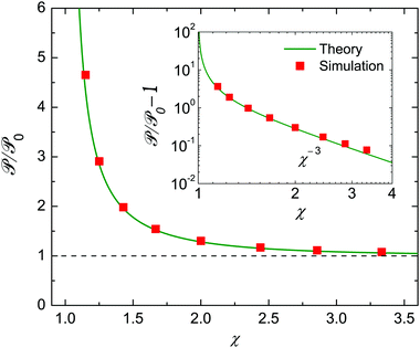 | ||
Fig. 6 Similar to Fig. 4, but for the power consumption of the squirmer, ![[scr P, script letter P]](https://www.rsc.org/images/entities/char_e52f.gif) , scaled by the unbounded value, , scaled by the unbounded value, ![[scr P, script letter P]](https://www.rsc.org/images/entities/char_e52f.gif) 0. In contrast to the velocities, 0. In contrast to the velocities, ![[scr P, script letter P]](https://www.rsc.org/images/entities/char_e52f.gif) depends also on modes |Bn| (n ≥ 2). Here |β| = |B2/B1| = 5 and Bn = 0 (n ≥ 3). The inset shows the χ−3 scaling of the nondimensional excess power depends also on modes |Bn| (n ≥ 2). Here |β| = |B2/B1| = 5 and Bn = 0 (n ≥ 3). The inset shows the χ−3 scaling of the nondimensional excess power ![[scr P, script letter P]](https://www.rsc.org/images/entities/char_e52f.gif) / /![[scr P, script letter P]](https://www.rsc.org/images/entities/char_e52f.gif) 0 − 1. 0 − 1. | ||
5.2 Co-swimming by combining tangential and normal squirming
We have shown in the previous sections that a swimmer employing solely tangential squirming modes, Bn, is always faster than the droplet, i.e. US > UD. Thus, the swimmer and droplet cannot remain concentric. With the idea of using artificial swimmers encapsulated in a droplet for controllable cargo delivery, it is attempting to try and tune the squirming gait such that the swimmer and droplet co-move with the same velocity US = UD and maintain a concentric configuration. We find that a squirmer combining both tangential and normal velocities is able to accomplish this, as shown below.The results in eqn (10) and (11) imply that the swimming velocities US and UD only depend on the first modes, A1 and B1. We define α ≡ A1/B1 to indicate the relative strength of the modes. By comparing eqn (10) and (11), we find that a particular value of α, denoted by αco, allows obtaining equal velocities, namely
 | (27) |
 | (28) |
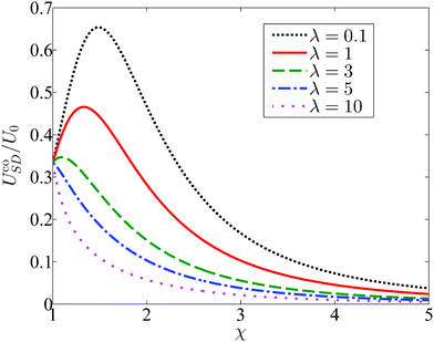
The influence of confinement χ and viscosity ratio λ on the resulting co-swimming speed is depicted in Fig. 7 by plotting the scaled co-moving speed UcoSD/U0, where U0 = 2B1/3 is the velocity of an unbounded squirmer with pure tangential modes. Even for a small viscosity ratio (λ = 0.1), the co-moving velocity UcoSD of the pair remains below 0.7U0. Simulations have been performed to determine the values of αco and UcoSD for the λ = 1 case, and here again the numerical results show excellent agreement with the theory (not shown).
The relation between the mode strength α and the size ratio χ required to achieve concentric co-swimming is given by eqn (27) for arbitrary viscosity ratio λ. When λ is fixed, the particular value αco ensuring co-swimming is easily chosen as a function of χ. Conversely, one may determine a particular size ratio χco as a function of α by solving the quintic equation. In the case of λ = 1, the required size ratio χco is simply given by
 | (29) |
5.3 Stability of the co-swimming state: axisymmetric configuration
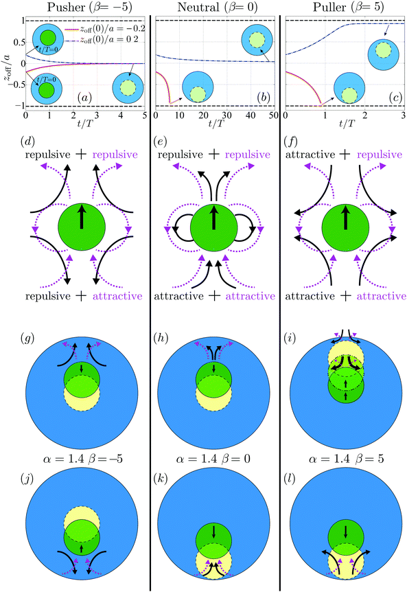
While the analysis above shows that co-swimming is possible, it is not clear a priori if such a configuration would be stable. In order to address the stability of swimmers, we perform numerical simulations for a swimmer–droplet pair, which is initially off-center but axisymmetric. The stability problem depends on many parameters including the size ratio χ, the viscosity ratio λ, the value of the mode ratio αco, the stresslet strength β, and the initial offset distance zoff. In order to make the problem tractable, we restrict the parameter values as χ = 0.5, λ = 1, αco = 1.4 and β = −5, 0, 5. We use zoff = zsq − zdp to denote the offset distance in the axial direction, where zsq and zdp are the axial positions of the swimmer and droplet, respectively, and all simulations start with zoff(t = 0) = ±0.2a.Fig. 8 (top row) displays the time evolution of zoff for a swimmer which starts initially ahead (blue dot-dashed lines) or behind (red solid lines) using a tangential squirming of β = −5 (pusher, a), β = 0 (neutral, b) and β = 5 (puller, c). The physical characteristic time T = b/B1 is used to scale the time t. For the co-moving pusher as shown in Fig. 8a, the offset zoff(0) decays to zero regardless of its sign: the concentric co-moving state is recovered and remains stable. The influence of zoff(0) for the co-moving neutral swimmer is shown in Fig. 8b. The concentric co-movement is seen to be stable if the swimmer is initially ahead of the droplet, but it is unstable and yields a finite-time collision between the swimmer and the droplet interface, when the swimmer is initially behind. In contrast, for the puller illustrated in Fig. 8c, the swimmer eventually touches the rear interface indicating instability when zoff(0) < 0, while when zoff(0) > 0, the pair reaches an eccentric co-moving state that is asymptotically stable. In the latter case, the swimmer is close to the front droplet interface but separated by a thin lubrication film which acts to stabilize their co-movement via hydrodynamic interactions. The asymptotically steady thickness of the film is about 0.08a.
The stability properties of the co-moving state seen in Fig. 8 may be interpreted physically by examining the disturbance flow field induced by the swimmer. We plot in Fig. 8 (middle row) the disturbance flow patterns corresponding to the co-moving swimming gaits which consist of normal squirming αco (dashed magenta lines) and tangential squirming β (solid black lines). The disturbance flow of the pusher and puller is characterized by a stresslet oriented in the swimming direction, decaying as 1/r2; that of the neutral swimmer resembles a source dipole along the same direction, decaying faster as 1/r3. The analysis of ref. 11 shows that the flow induced by the A1 mode squirming is equivalent to that by a neutral swimmer with B1 = A1. The details of this disturbance flow dictate hydrodynamic interactions between the swimmer and its environment. As can be seen in Fig. 8d, a body located in front of or behind a pusher tends to be repelled by it while it will tend to be attracted for a puller. In contrast for a neutral swimmer with A1 > 0, ahead of the swimmer will be repulsive while it will tend to be attractive behind it.
We then link in Fig. 8 (bottom row) the disturbance flow of the swimmer and its relative movement with respect to the droplet, where solid/dashed circles denote the swimmer's initial/final location (the dot-dashed circles denote an intermediate position). As seen in Fig. 8g, for a co-moving pusher initially ahead of the droplet center, the repulsive flow in front of the swimmer, consisting of both repulsive flows from tangential squirming of β = −5 and normal squirming of α = 1.4, is stronger than its rear counterpart and brings the swimmer back to the center (stable). For the same swimmer but initially closer to the rear of the droplet as depicted in Fig. 8j, the rear flows dominate. While the flows induced by the two squirming modes are of opposite sign, the repulsive flow arising from tangential squirming is likely to overcome the attractive one of the normal squirming due to the faster-decaying and shorter-ranged disturbance flow of the latter (1/r3vs. 1/r2).
The behavior of the co-moving neutral swimmer can be understood along the same vein, as illustrated in Fig. 8h and k, and similarly for the puller when its is initially located behind that of the droplet (Fig. 8l). The only non-intuitive result is the asymptotically-stable eccentric location of the co-moving puller that is originally closer to the droplet front as illustrated in Fig. 8i. Initially, the gap between the swimmer and interface is relatively large, therefore the longer-ranged attractive flow from the tangential squirming will outweigh the shorter-ranged repulsive one from the normal squirming, and the swimmer will be attracted towards the interface. As the gap width decreases, the repulsive short-range flow becomes stronger, eventually dominating and preventing the swimmer from further approaching the interface. This explains, at least qualitatively, why hydrodynamic interactions lead in this situation to a stable eccentric configuration.
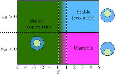
Additional simulations were then performed with 1/χ ranging from 0.3 to 0.7 and β ranging from −5 to 5. These simulations show that the stability properties of the co-moving state are independent of the size ratio χ and depend only on β. As shown in Fig. 9, when β ≤ 0, the concentric co-movement state is stable regardless of the sign of the initial offset zoff. When β ≥ 1, the eccentric co-moving state is stable if the swimmer is initially ahead (zoff > 0) while no stable co-moving configuration is observed otherwise (zoff < 0).
5.4 Stability of the co-swimming state: non-axisymmetric configuration
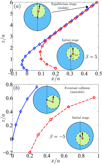
We next address the issue of stability when the initial position of the swimmer center is not aligned with the droplet along the z axis. Since the system is not axisymmetric in this case, we employ numerical simulations allowing the swimmer to display rotational motion. We track the two offset distances in x and z directions with xoff = xsq − xdp and zoff = zsq − zdp. When χ = 2 and αco = 1.4, we consider three types of swimmers, namely a pusher with stresslet strength β = −5, a neutral swimmer with β = 0, and a puller with β = 5.We first plot in Fig. 10a the trajectories of pullers in the laboratory frame with an initial offset (xoff,zoff) = (0.2a,0.2a). Initially the system is not axisymmetric but after a slight rotation the swimmer settles in an axisymmetric configuration. Although the rotational motion is small, it occurs early in the dynamics, in particular before the swimmer closely approaches the droplet. After that, the system becomes equivalent to the axisymmetric situation considered in Fig. 8c and the swimmer reaches a stable state maintaining a thin gap with the droplet.
Next we show in Fig. 10b the trajectories of pushers with an initial offset (xoff,zoff) = (0.2a,−0.2a). The swimmer slightly rotates but in this case does not align with the droplet axisymmetrically. Instead, due to the attractive flows in the lateral directions, the pusher approaches the droplet and eventually collides with it. Other cases with the initial offset (xoff,zoff) = (0.2a,0.2a) or (0.2a,0) exhibit similar behaviors as in Fig. 10b with no stable configurations. Also pullers with the initial offset (xoff,zoff) = (0.2a,−0.2a) or (0.2a,0) and neutral swimmers with (xoff,zoff) = (0.2a,±0.2a) or (0.2a,0) do not settle a stable configuration. Additional simulations by changing the size ratio and stresslet strength lead to similar results.
6 Conclusion
In this paper, we have studied in the creeping flow regime the dynamics of a spherical squirmer encapsulated in an undeformable droplet using both theory and computations. The incompressible Stokes equations were first solved analytically, and when the swimmer and droplet are concentric, we obtained exact solutions of the swimmer and droplet velocities, the flow velocity fields and their dissipated power. Along with this analytic approach, numerical simulations based on a boundary element method were performed and the numerical results agreed well with the theoretical results.The analytical solutions provide a useful physical picture of the instantaneous dynamics for the concentric configuration of the squirmer and droplet. For a squirmer using pure tangential surface actuations, although the concentric geometry is only transient, the theoretical results state that the swimmer is always faster than the droplet. When the normal surface velocities are incorporated on top of tangential modes, the squirmer and droplet are able to co-swim with the same velocity and thus to remain concentric.
When the swimmers are slightly displaced from the concentric position, we found that they would either return to the center (stable), deviate further and eventually touch the droplet interface (unstable), or reach an eccentric steady-state position (stable). Such final states depend on swimming gaits or relative locations of swimmers.
The ultimate goal of encaging swimmers is to help transport and deliver small chemical payloads, and thus a lot of future work lies ahead for swimmer–droplet complexes. Questions including swimming near complex boundaries or near walls, or non-axisymmetrically, will have to be tackled. Surfactants, which are commonly used in droplet-based microfluidics to prevent coalescence, could perhaps be used here to prevent collision between the swimmers and the interface, with interesting physical consequences. Finally, if heterogeneous fluid mixtures are to be transported in the droplet, it will be important to quantify their mixing and chemical fate as they move along with the swimmer.
Appendix
Constants in flow solution
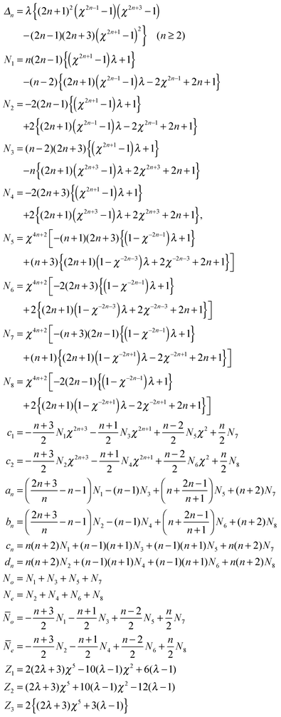
The undefined constants for the fluid velocity fields in eqn (13) and the power calculations in eqn (15) are given in Table 1.Acknowledgements
Gioele Balestra is acknowledged for his helpful suggestions in making the 3D schematic plot. The computer time is provided by the Swiss National Supercomputing Centre (CSCS) under project ID s603 and by SNIC (Swedish National Infrastructure for Computing). A VR International Postdoc Grant from Swedish Research Council ‘2015-06334’ (L. Z.), an ERC starting grant ‘SimCoMiCs 280117’ (F. G.), a Marie Curie CIG Grant (E. L.) and an ERC Consolidator grant (E. L.) are gratefully acknowledged. Open Access funding provided by the Max Planck Society.References
- M. He, J. S. Edgar, G. D. Jeffries, R. M. Lorenz, J. P. Shelby and D. T. Chiu, Anal. Chem., 2005, 77, 1539–1544 CrossRef CAS PubMed.
- S. Köster, F. E. Angile, H. Duan, J. J. Agresti, A. Wintner, C. Schmitz, A. C. Rowat, C. A. Merten, D. Pisignano and A. D. Griffiths, et al. , Lab Chip, 2008, 8, 1110–1115 RSC.
- M. Chabert and J.-L. Viovy, Proc. Natl. Acad. Sci. U. S. A., 2008, 105, 3191–3196 CrossRef CAS PubMed.
- J. Clausell-Tormos, D. Lieber, J.-C. Baret, A. El-Harrak, O. J. Miller, L. Frenz, J. Blouwolff, K. J. Humphry, S. Köster and H. Duan, et al. , Chem. Biol., 2008, 15, 427–437 CrossRef CAS PubMed.
- H. Wen, Y. Yu, G. Zhu, L. Jiang and J. Qin, Lab Chip, 2015, 15, 1905–1911 RSC.
- L. Zhang, J. J. Abbott, L. Dong, B. E. Kratochvil, D. Bell and B. J. Nelson, Appl. Phys. Lett., 2009, 94, 064107 CrossRef.
- S. Tottori, L. Zhang, F. Qiu, K. K. Krawczyk, A. Franco-Obregón and B. J. Nelson, Adv. Mater., 2012, 24, 811–816 CrossRef CAS PubMed.
- Y. Ding, F. Qiu, X. C. Solvas, F. W. Y. Chiu, B. J. Nelson and A. deMello, Micromachines, 2016, 7, 25 CrossRef.
- D. Tsemakh, O. M. Lavrenteva and A. Nir, Int. J. Multiphase Flow, 2004, 30, 1337–1367 CrossRef CAS.
- M. J. Lighthill, Commun. Pure Appl. Math., 1952, 5, 109–118 CrossRef.
- J. R. Blake, J. Fluid Mech., 1971, 46, 199–208 CrossRef.
- V. Magar, T. Goto and T. Pedley, Q. J. Mech. Appl. Math., 2003, 56, 65–91 CrossRef.
- T. Ishikawa, M. P. Simmonds and T. J. Pedley, J. Fluid Mech., 2006, 568, 119–160 CrossRef.
- S. Michelin and E. Lauga, Phys. Fluids, 2010, 22, 111901 CrossRef.
- A. Doostmohammadi, R. Stocker and A. M. Ardekani, Proc. Natl. Acad. Sci. U. S. A., 2012, 109, 3856–3861 CrossRef CAS PubMed.
- A. Zöttl and H. Stark, Phys. Rev. Lett., 2012, 108, 218104 CrossRef PubMed.
- O. S. Pak and E. Lauga, J. Eng. Math., 2014, 88, 1–28 CrossRef.
- C. Datt, L. Zhu, G. J. Elfring and O. S. Pak, J. Fluid Mech., 2015, 784, R1 CrossRef.
- J.-B. Delfau, J. Molina and M. Sano, EPL, 2016, 114, 24001 CrossRef.
- H. Lambs, Hydrodynamics, Cambridge University Press, 6th edn, 1932 Search PubMed.
- J. Happel and H. Brenner, Low Reynolds Number Hydrodynamics, Noordhoff International Publishing, Leyden, 1973 Search PubMed.
- C. Pozrikidis, Boundary integral and singularity methods for linearized viscous flow, Cambridge University Press, 1992 Search PubMed.
- J. J. L. Higdon and G. P. Muldowney, J. Fluid Mech., 1995, 298, 193–210 CrossRef CAS.
- L. Zhu, E. Lauga and L. Brandt, J. Fluid Mech., 2013, 726, 285–311 CrossRef.
- D. Dunavant, Int. J. Numer. Meth. Eng., 1985, 21, 1129–1148 CrossRef.
- C. Pozrikidis, A practical guide to boundary element methods with the software library BEMLIB, CRC Press, 1st edn, 2002 Search PubMed.
- A. Zinchenko and R. Davis, J. Fluid Mech., 2006, 564, 227–266 CrossRef.
- A. Z. Zinchenko, M. A. Rother and R. H. Davis, Phys. Fluids, 1997, 9, 1493–1511 CrossRef CAS.
- A. Zinchenko and R. Davis, J. Fluid Mech., 2013, 725, 611–663 CrossRef.
- L. Zhu and F. Gallaire, J. Fluid Mech., 2016, 798, 955–969 CrossRef.
- H. C. Berg, E. coli in Motion, Springer, New York, 2004 Search PubMed.
- J. P. Hernandez-Ortiz, P. T. Underhill and M. D. Graham, J. Phys.: Condens. Matter, 2009, 21, 204107 CrossRef PubMed.
- S. E. Spagnolie and E. Lauga, J. Fluid Mech., 2012, 700, 105 CrossRef.
- R. E. Goldstein, Annu. Rev. Fluid Mech., 2015, 47, 343–375 CrossRef PubMed.
- N. Yoshinaga, K. H. Nagai, Y. Sumino and H. Kitahata, Phys. Rev. E: Stat., Nonlinear, Soft Matter Phys., 2012, 86, 016108 CrossRef PubMed.
- M. Schmitt and H. Stark, EPL, 2013, 101, 44008 CrossRef.
- S. Herminghaus, C. C. Maass, C. Krüger, S. Thutupalli, L. Goehring and C. Bahr, Soft Matter, 2014, 10, 7008–7022 RSC.
- C. C. Maass, C. Krüger, S. Herminghaus and C. Bahr, Annu. Rev. Condens. Matter Phys., 2016, 7, 171–193 CrossRef CAS.
- R. Golestanian, T. B. Liverpool and A. Ajdari, Phys. Rev. Lett., 2005, 94, 220801 CrossRef PubMed.
- J. L. Anderson, Annu. Rev. Fluid Mech., 1989, 21, 61–99 CrossRef.
- W. Wang, W. Duan, S. Ahmed, T. E. Mallouk and A. Sen, Nano Today, 2013, 8, 531–554 CrossRef CAS.
- P. H. Colberg, S. Y. Reigh, B. Robertson and R. Kapral, Acc. Chem. Res., 2014, 47, 3504 CrossRef CAS PubMed.
Footnotes |
| † These authors contributed equally to this work. |
| ‡ Current address: Linné Flow Centre and Swedish e-Science Research Centre (SeRC), KTH Mechanics, SE-100 44 Stockholm, Sweden. |
| § Current address: Department of Mechanical and Aerospace Engineering, Princeton University, Princeton, NJ-08544, USA. |
| This journal is © The Royal Society of Chemistry 2017 |

