
Investigation of polyacrylamide based hydroxide ion-conducting electrolyte and its application in all-solid electrochemical capacitors†
Jak
Li
 a,
Jinli
Qiao
b and
Keryn
Lian
*a
a,
Jinli
Qiao
b and
Keryn
Lian
*a
aFlexible Electronics and Energy Laboratory, Department of Material Science and Engineering, University of Toronto, 184 College St., Toronto, ON, Canada M5S 3E4. E-mail: jak.li@mail.utoronto.ca; k.lian@utoronto.ca
bDonghua University, College of Environment Science and Engineering, 2999 Ren'min North Road, Shanghai, China 201620. E-mail: qiaojl@dhu.edu.cn
First published on 10th July 2017
Abstract
A new hydroxide (OH−) ion-conducting polymer electrolyte comprised of tetraethylammonium hydroxide (TEAOH) and polyacrylamide (PAM) was developed. This electrolyte exhibits excellent ionic conductivity greater than 10 mS cm−1 at room temperature and stable shelf-life over an 80 day exposure in various environments. Solid electrochemical double layer capacitors (EDLC) were fabricated and compared to their liquid counterparts. While all EDLC devices showed similar capacitance, the solid EDLC devices outperformed the liquid devices in cycle-life and offered additional advantages such as safety, light weight, and a flexible form factor. Based on structural, thermal, and chemical analyses, this excellent performance can be attributed to a stable amorphous structure and the higher degree of hydration of the polymer electrolyte promoted by a slight hydrolysis between TEAOH and PAM.
Introduction
The emergence of flexible and wearable electronics has led to the rapid development of solid-state, light-weight, and thin energy storage devices that are safe, compact, and shape conforming for large scale reel-to-reel fabrication.1–6 Polymer electrolytes are key enablers for such applications,7–9 since they have valuable advantages over traditional liquid electrolytes despite intrinsically lower ionic conductivities. Commonly studied polymer electrolytes include aqueous, organic, and ionic liquids.10–12 While the focus has mostly been on H+ ion-conducting systems, OH− ion-conducting analogues have lately gained attention.13,14 For energy storage, OH− ion-conducting polymer electrolytes are still in an early stage of development, but promise benefits such as compatibility with many carbon materials and can facilitate desirable redox reactions with low cost transition metals such as Ni and Zn. Among the various OH− ion conductors, potassium hydroxide (KOH) is the most extensively utilized in both liquid and polymer systems for batteries and electrochemical capacitors (EC).15–22 Unfortunately, in the polymer form KOH is susceptible to crystallization which severely hinders ionic conductivity and electrode/electrolyte interfacial properties.23In order to improve the longevity of OH− ion-conducting polymer electrolytes, we have developed an alternative system utilizing tetraethylammonium hydroxide (TEAOH) in poly(vinyl alcohol) (PVA), which demonstrated superior shelf-life compared to KOH–PVA.23 This electrolyte was successfully leveraged for ultra high rate solid-state AC line-filtering applications.24 Additionally, a comparative study of TEAOH in several polymers revealed that the effects of structure, hydration, and functional group significantly influenced the ionic conductivity and shelf-life of polymer electrolytes.25
In this study, a new class of OH− ion-conducting polymer electrolytes based on TEAOH and poly(acrylamide) (PAM) was developed and characterized. A detailed study of its structural, thermal, and chemical properties and its electrochemical performance revealed synergistic effects between TEAOH and PAM. As a water soluble polymer, PAM is known for its high hydrophilicity and is commonly used for water treatment applications.26 This polymer was selected for its amorphous structure to promote OH− ion-conduction and for its hydrophilicity to improve the degree of hydration of the polymer electrolyte. An optimized TEAOH–PAM polymer electrolyte was compared to a liquid TEAOH electrolyte in electric double layer capacitor (EDLC) devices utilizing multi-walled carbon nanotube (MWCNT) electrodes. This study provides new evidence in terms of the effects of structure, hydration, and functional groups on OH− ion-conduction in polymer electrolytes and demonstrates the feasibility of transitioning from bulky liquid devices to safer, light-weight, and thin solid devices.
Experimental
Polymer electrolyte preparation and conditioning
A 5 wt% poly(acrylamide) (PAM, Sigma-Aldrich, Mw = 2![[thin space (1/6-em)]](https://www.rsc.org/images/entities/char_2009.gif) 000000) solution was prepared by dissolving the as-received polymer powder in water and stirring at 80 °C for 24 hours. Six precursor solutions of tetraethylammonium hydroxide (TEAOH, Alfa Aesar, 35 wt% in H2O) and PAM were prepared by mixing the 5 wt% PAM solution with the 35 wt% TEAOH solution until the mixtures were homogeneous. Table 1 shows the weight ratio (wt ratio) and molar ratio (mol. ratio) of the TEAOH and PAM blends (assuming no water).
000000) solution was prepared by dissolving the as-received polymer powder in water and stirring at 80 °C for 24 hours. Six precursor solutions of tetraethylammonium hydroxide (TEAOH, Alfa Aesar, 35 wt% in H2O) and PAM were prepared by mixing the 5 wt% PAM solution with the 35 wt% TEAOH solution until the mixtures were homogeneous. Table 1 shows the weight ratio (wt ratio) and molar ratio (mol. ratio) of the TEAOH and PAM blends (assuming no water).
| Composition | TEAOH–PAM (wt ratio) | TEAOH–PAM (mol. ratio) |
|---|---|---|
| 1 | 42–58 | 10000:1 |
| 2 | 50–50 | 13333:1 |
| 3 | 69–31 | 30000:1 |
| 4 | 75–25 | 40000:1 |
| 5 | 79–21 | 50000:1 |
| 6 | 83–17 | 66667:1 |
The polymer electrolytes were stored and conditioned under designated relative humidity (RH) conditions in desiccators at 25 °C. Saturated salt solutions of KNO3, K2CO3, and LiCl were kept in the desiccators to achieve stable environments of ca. 75, 45, and 15% RH, representing hydrated, ambient, and dehydrated states, respectively.25,27
Material characterizations
X-ray diffraction (XRD) analyses were conducted using a Philips XRD system with a PW1830 HT generator, a PW 1050 goniometer, and PW3710 control electronics. The samples were measured using a monochromatized Cu-Kα anode source operating at 40 kV/40 mA. The diffraction patterns were recorded from 5° to 50° 2θ with a step scan of 0.02° 2θ. Differential scanning calorimetry (DSC) experiments were carried out using a TA Instruments Q50 DSC in a nitrogen environment from 30 to 250 °C with a heating rate of 10 °C min−1. The degree of hydration was calculated from DSC thermograms according to eqn (1)28 (TA Instruments Application Notes: TA384), where ΔHH2O is the total enthalpy for the thermal events attributed to the release of water, incorporating all bonded waters, and ΔHν,H2O is the standard heat of vaporization for water (2260 J g−1). | (1) |
Infrared (IR) spectra were recorded at room temperature on a Thermo Scientific Nicolet iS5 FT-IR spectrometer with iD5 attenuated total reflectance (ATR) module with pressure applied for intimate contact. Unless otherwise specified, all samples were prepared under ambient conditions at 25 °C.
Solid and liquid electrochemical capacitors (ECs)
Metallic EC cells were fabricated using Ni foil electrodes with a geometric area of 1 cm2. These cells were assembled in the following steps: (i) casting the TEAOH–PAM polymer electrolyte precursor solutions on two Ni electrodes and drying them under ambient conditions; (ii) assembling the cell by sandwiching the two electrodes together; and (iii) sealing the cell with a chemically inert tape to maintain structural integrity of the solid cell. The thickness of the polymer electrolyte was measured and calculated to be ca. 200 μm using a Mitutoyo digital micrometer at six different points of the cell.To construct EDLC electrodes, a homogeneous carbon ink was doctor bladed onto Ni foils, and the coated sheets were heated and cut into pieces with active areas of 1 cm2. The carbon ink consisted of 60 wt% “as-received” multi-walled carbon nanotubes (MWCNT),29 20 wt% commercial graphite, and 20 wt% cross-linked poly(vinyl alcohol) (PVA, Sigma-Aldrich, Mw = 145000) as the binder.30 The average loading of each electrode was 1.3 ± 0.4 mg cm−2. Ten solid, symmetrical EDLC devices using MWCNT electrodes and TEAOH–PAM were assembled, each with an overall thickness of ca. 0.05 cm and an active area of 1 cm2 (Fig. 1a), and ten liquid EDLC devices were constructed similarly using a filter paper soaked in 0.5 M TEAOH (ca. 200 μm) as the separator/electrolyte (Fig. 1b).
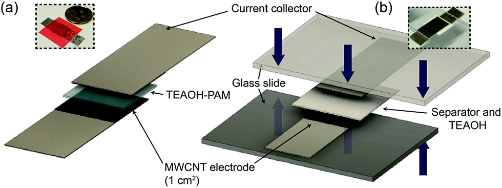 | ||
| Fig. 1 Schematic of (a) solid and (b) liquid EDLC devices in a sandwiched configuration, where the liquid EDLC is subjected to ca. 5 psi pressure denoted by the blue arrows. | ||
Electrochemical characterizations
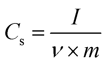
All cells were characterized using cyclic voltammetry (CV), galvanostatic charge/discharge (GCD) with a current density of 5 mA cm−2, and electrochemical impedance spectroscopy (EIS) on a CHI 760 C bipotentiostat. The EIS spectra were recorded from 0.1 to 106 Hz with a voltage amplitude of 5 mV without dc bias. The ionic conductivity was calculated based on eqn (2). The specific capacitance based on the CV was calculated using eqn (3) and the capacitance retention through GCD was calculated using eqn (4).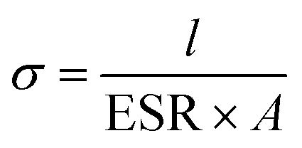 | (2) |
 | (3) |
 | (4) |
Results and discussion
In this study, the ionic conductivity of TEAOH–PAM in various compositions was first measured in the hydrated condition to find an optimal concentration. Three compositions were selected for shelf-life studies under ambient and controlled environments. The material properties of the best electrolyte were characterized to explore the interaction between TEAOH and PAM. The same electrolyte was used in solid EDLC devices with MWCNT electrodes and compared to a liquid device to evaluate the performance of the solid electrolyte.Optimization of TEAOH–PAM
The ionic conductivity of TEAOH–PAM is shown in Fig. 2 as a function of TEAOH content in the hydrated condition. At lower TEAOH concentrations, the ionic conductivity increased with TEAOH due to the dissociation of ions. The decrease in ionic conductivity with TEAOH concentrations greater than 75 wt% was due to the agglomeration of OH− ions, which hindered ion mobility, similar to that in aqueous TEAOH solutions.25 This indicated that OH− ion-conduction in TEAOH–PAM is highly dependent on water in the hydrated condition or “gel-like”, as observed in TEAOH with other polymer media.17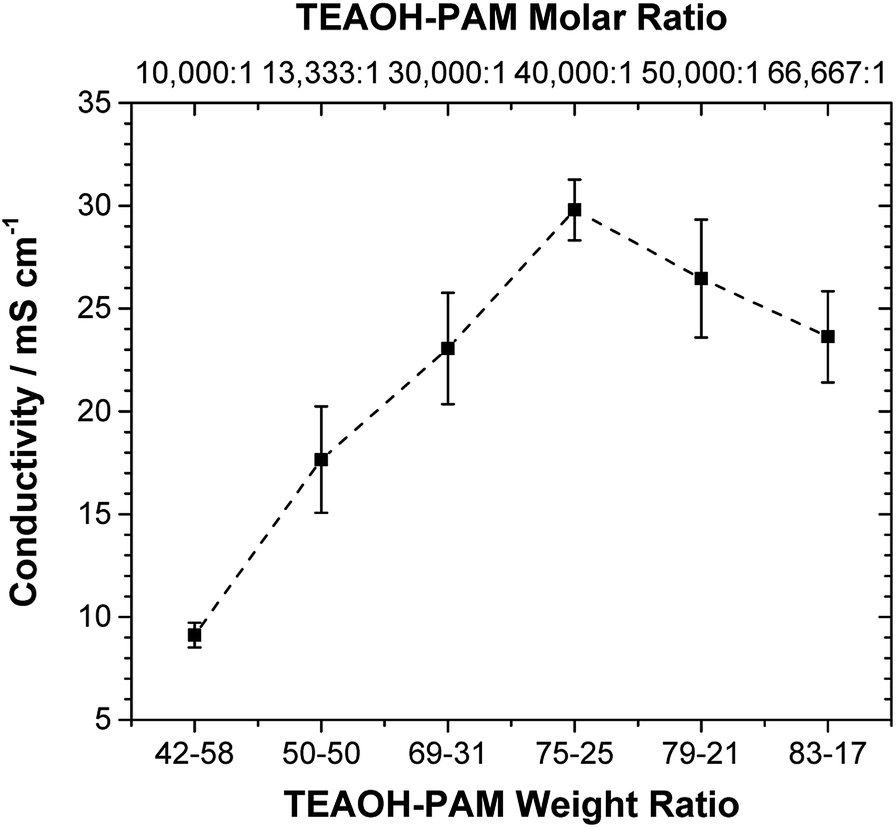 | ||
| Fig. 2 Ionic conductivity of TEAOH–PAM with increasing TEAOH content under hydrated conditions. | ||
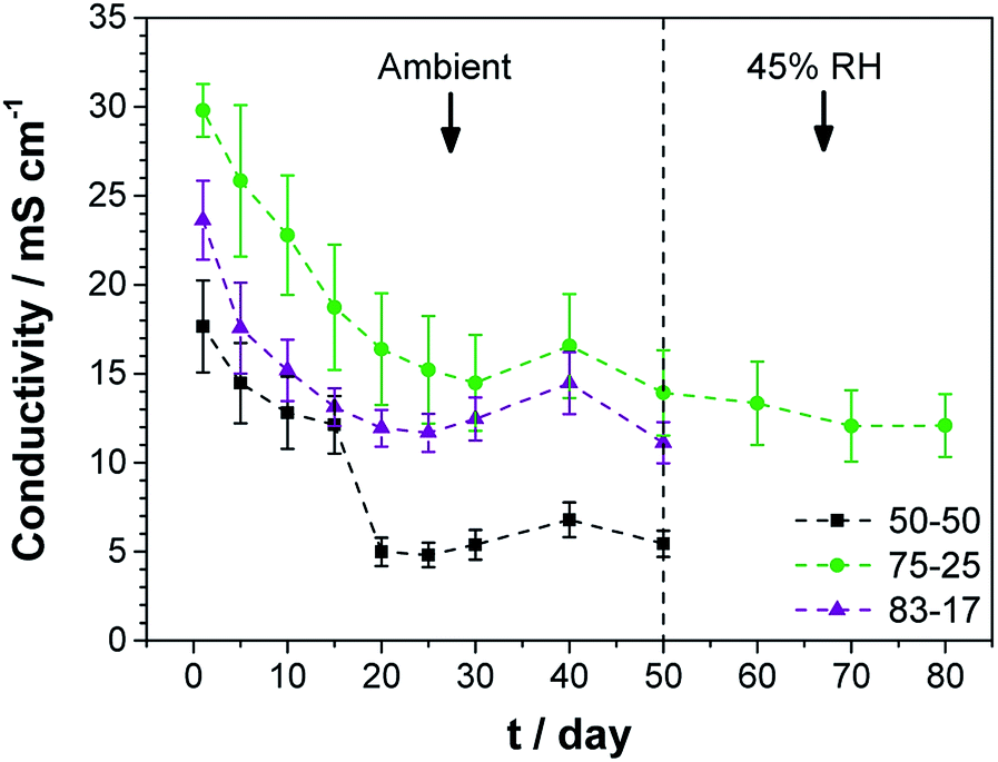
A high performance polymer electrolyte for ECs not only requires good ionic conductivity, but also long term environmental stability. The TEAOH–PAM(75–25) composition, having demonstrated the highest ionic conductivity under hydrated conditions, was compared to TEAOH–PAM(50–50) and TEAOH–PAM(83–17) in a shelf-life study as shown in Fig. 3. For the first 14 days, the ionic conductivity of all compositions steadily decreased as the polymer electrolytes established equilibrium with the environment. The lower ionic conductivity under ambient conditions compared to under hydrated conditions was likely due to decreased hydration of the system.
 | ||
| Fig. 3 Ionic conductivity tracking of TEAOH–PAM in three different compositions. | ||
A notable drop in ionic conductivity of TEAOH–PAM(50–50) occurred after 14 days under ambient conditions; in contrast, TEAOH–PAM(75–25) and TEAOH–PAM(83–17) maintained their ionic conductivity for 50 days. This observation indicated that TEAOH not only provided OH− ions for conduction, but also contributed to the hydration of the polymer electrolyte which helped sustain good ionic conductivity. A concentration of ca. 75 wt% TEAOH was sufficient to maintain a high ionic conductivity under ambient conditions; higher TEAOH concentrations did not benefit the longevity of the polymer electrolyte. Thus, TEAOH–PAM(75–25) was selected as the optimal composition under both hydrated and ambient conditions.
To minimize the influence of RH fluctuations from ambient conditions as observed from days 30 to 50, TEAOH–PAM(75–25) was stored and tested for an additional 30 days under 45% RH, a reasonable simulation of ambient conditions, and showed no significant change in ionic conductivity (higher than 10 mS cm−1). Throughout the tracking period of 80 days the TEAOH–PAM(75–25) polymer electrolyte demonstrated excellent performance and stability under ambient and 45% RH environments.
Material characterizations of TEAOH–PAM
Further characterizations of structure stability, degree of hydration, and molecular bonding of the TEAOH–PAM(75–25) polymer electrolyte were carried out as these properties of polymer electrolytes play an important role in ion-conduction. Amorphous structures allow flexibility and segmental motion of the polymer chain to facilitate the movement of ions under an electric field.31 Hydration of the polymer electrolyte serves two functions: plasticizing the system to promote amorphous structures and providing accessible paths of conduction for the ions. | ||
| Fig. 4 XRD of TEAOH(s), PAM film under 45% RH conditions, and the TEAOH–PAM(75–25) polymer electrolyte under 75% RH and 45% RH conditions. | ||
With the diffraction patterns of TEAOH and PAM as indicators of the least and most desirable structures respectively, TEAOH–PAM was analyzed by XRD after conditioning in 75% RH and 45% RH (Fig. 4). Any change in structure with respect to the environment was correlated to the change in ionic conductivity observed during the shelf-life study. Under both conditions, TEAOH–PAM displayed broad diffraction patterns, indicating that the material structure remained amorphous. This also explains the stable ionic conductivity of TEAOH–PAM in both environments over the 80 day test period.
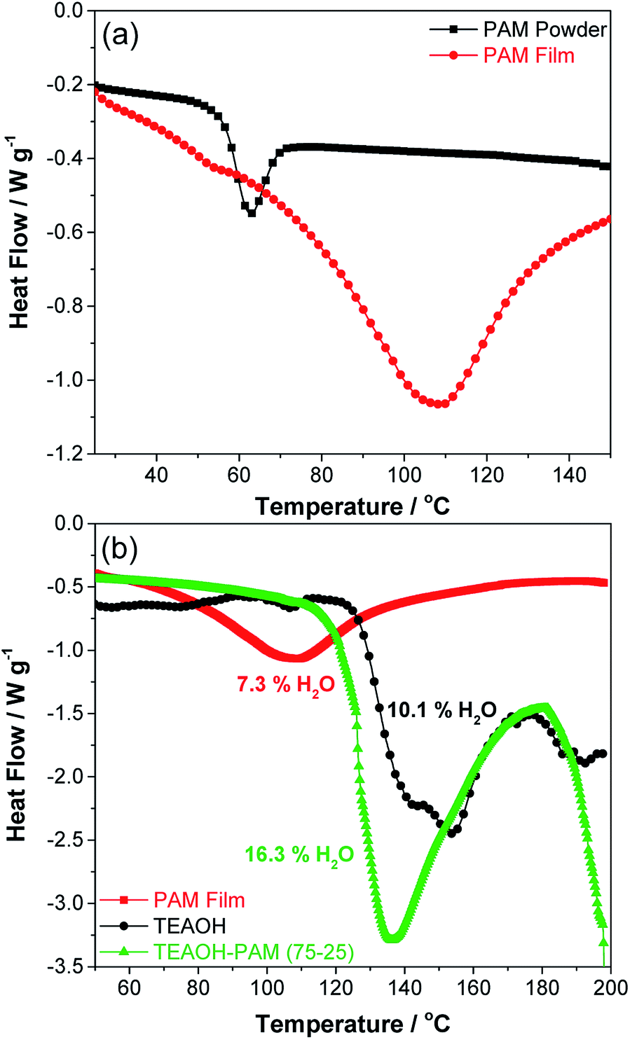 | ||
| Fig. 5 DSC thermograms of (a) PAM powder vs. PAM film and (b) PAM film, TEAOH, and TEAOH–PAM. | ||
The exothermic peak at 150 °C for TEAOH can be ascribed to the release of water, prior to the decomposition temperature of TEAOH at 200 °C.35 The higher water release temperature over the PAM film indicated that water was bound even tighter in TEAOH than in the PAM film. Meanwhile, the exothermic peak temperature of TEAOH–PAM(75–25) fell between PAM film and TEAOH at 136 °C. This result suggests that introducing TEAOH into PAM prolonged water retention of PAM, where higher concentrations of TEAOH provided sites for more effective hydrogen bonding of water compared to the loosely bound water in PAM powder and PAM film.
In addition, the amount of heat released during the thermal events for the different materials also varied. To quantify the level of hydration in the polymer electrolyte and its components, the water content of the samples was calculated using eqn (1) (experimental), where the limits of integration was set from the onset of each enthalpy peak to the end of the thermal event at 170 °C. The water content in PAM film and TEAOH was determined to be 7.3% and 10.1% respectively, confirming that both PAM and TEAOH are hygroscopic materials. Interestingly, the water content of TEAOH–PAM(75–25) was 16.3%, higher than both individual components, suggesting that TEAOH not only enhanced the bonding of water in the system, but also promoted higher water uptake. While the high degree of hydration in TEAOH–PAM(75–25) provided more hydrogen bonding sites for OH− ion-conduction, it was also a key contributor in plasticizing the system to preserve an amorphous structure. Both factors facilitated OH− ion-conduction in the polymer electrolyte system. The thermal stability of the polymer electrolyte was further explored by studying the temperature dependence of the ionic conductivity up to 80 °C. The activation energy for OH− ion-conduction was estimated to be 23.4 kJ mol−1 by fitting the data to the Arrhenius equation, which is reasonable compared to the literature, typically associated with a type of structural diffusion mechanism36,37 (see Fig. S2 in the ESI†). It should be noted that data deviates from linearity at higher temperatures, which could suggest the involvement of other OH− ion-mechanisms. Further investigation is underway to clarify the OH− ion-conduction mechanism of these polymer electrolytes.
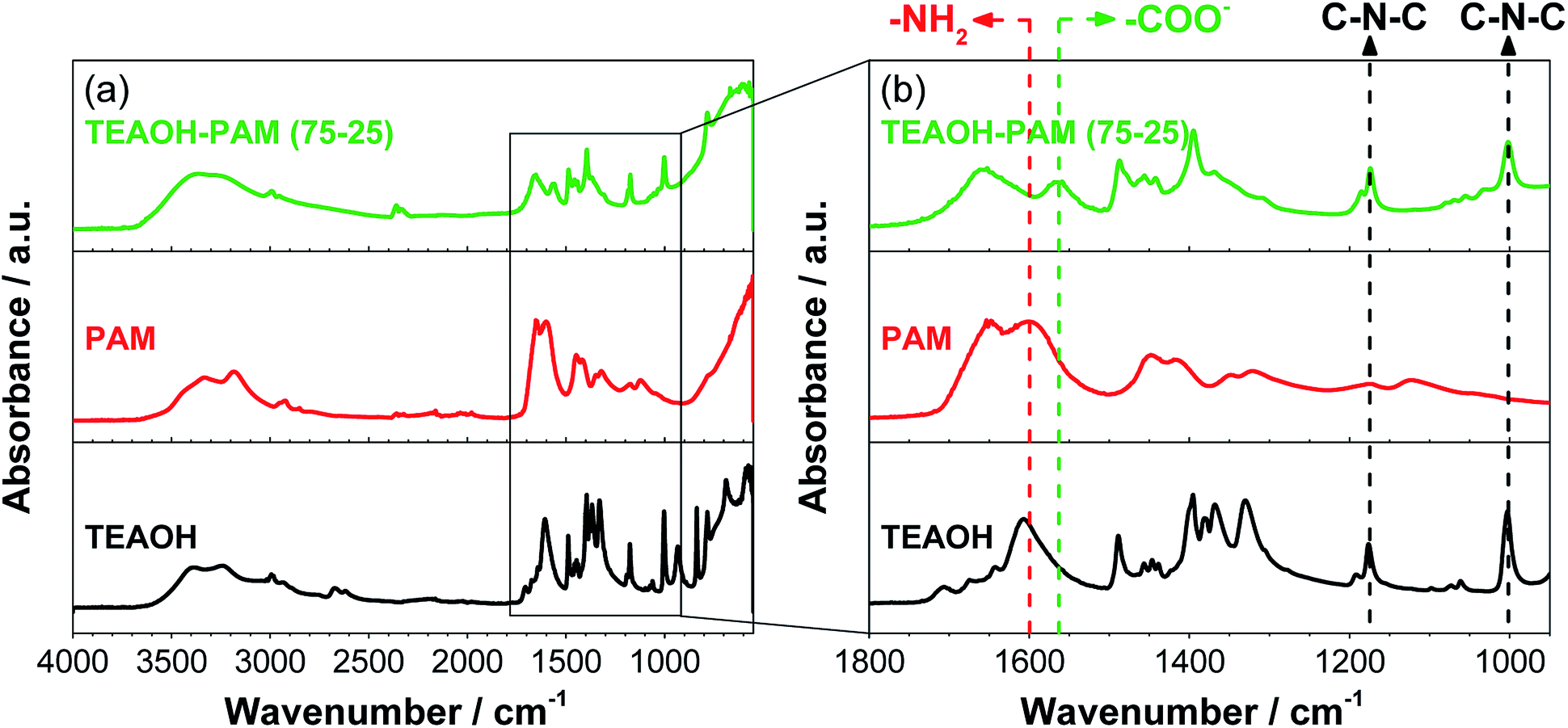 | ||
| Fig. 6 FTIR-ATR spectra of TEAOH, PAM, TEAOH–PAM; (a) the full range of the spectra and (b) the fingerprint region. | ||
The IR fingerprint region is typically at wavenumbers below 1800 cm−1. Fig. 6b shows an enlarged view of this region, where TEAOH has two characteristic peaks at 1176 cm−1 and 1003 cm−1 from asymmetrical C–N–C stretches of the tetraethylammonium cation23 and two characteristic peaks of PAM located at 1648 cm−1 and 1601 cm−1 from the carbonyl (C![[double bond, length as m-dash]](https://www.rsc.org/images/entities/char_e001.gif) O) and the amide (–NH2) stretches of the PAM functional groups, respectively.38 While the TEAOH–PAM(75–25) spectra contained the characteristics of both the C–N–C stretch from TEAOH and the CO stretch from PAM, the obscuring of the –NH2 stretch at 1601 cm−1 and the appearance of a new peak at 1564 cm−1 were observed. This new peak can be attributed to the asymmetric stretch of the carboxylate ion (–COO−).39–41 Specifically, this ion species is a product of slight hydrolysis of the amide functional group in PAM, which resulted in the reduced intensity of the –NH2 stretch. Since carboxylate ions are known for their water absorption properties in acrylate polymers,42 their presence can be used to explain the higher water uptake and retention of the polymer electrolyte over its constituent parts. Nevertheless, the slight hydrolysis did not seem to influence the pH of the polymer electrolyte and sufficient OH− ions are still present for conduction under an electric field. The higher level of hydration not only provided additional pathways for the conduction of OH− ions, but may have also led to the structure being appropriately plasticized rendering TEAOH–PAM(75–25) a promising material system as an OH− ion-conducting polymer electrolyte for thin, solid-state ECs.
O) and the amide (–NH2) stretches of the PAM functional groups, respectively.38 While the TEAOH–PAM(75–25) spectra contained the characteristics of both the C–N–C stretch from TEAOH and the CO stretch from PAM, the obscuring of the –NH2 stretch at 1601 cm−1 and the appearance of a new peak at 1564 cm−1 were observed. This new peak can be attributed to the asymmetric stretch of the carboxylate ion (–COO−).39–41 Specifically, this ion species is a product of slight hydrolysis of the amide functional group in PAM, which resulted in the reduced intensity of the –NH2 stretch. Since carboxylate ions are known for their water absorption properties in acrylate polymers,42 their presence can be used to explain the higher water uptake and retention of the polymer electrolyte over its constituent parts. Nevertheless, the slight hydrolysis did not seem to influence the pH of the polymer electrolyte and sufficient OH− ions are still present for conduction under an electric field. The higher level of hydration not only provided additional pathways for the conduction of OH− ions, but may have also led to the structure being appropriately plasticized rendering TEAOH–PAM(75–25) a promising material system as an OH− ion-conducting polymer electrolyte for thin, solid-state ECs.
Exploration of TEAOH–PAM enabled MWCNT EDLCs
Solid-state EDLC devices were developed using MWCNT-Ni electrodes and the TEAOH–PAM(75–25) polymer electrolyte in a sandwiched configuration (Fig. 1 experimental). The reported capacitance was normalized to the loading of the electrode material (1.3 ± 0.4 mg cm−2). A low carbon loading was used for a systematic initial exploration of the interaction between the electrolyte and electrodes. Additional investigations on the relationship between solid electrolytes and electrodes with different carbon loadings are under way.The average values of ten liquid and ten solid EDLC devices was first determined from the impedance analysis by deconvoluting the spectra into the real part of the capacitance (C′) and the imaginary part of the capacitance (C′′), see Fig. 7. C′ portrays the deliverable charge stored in the EC across the range of frequencies, while the maximum of the C′′ vs. frequency curve represents a time constant, which can be used as a “factor of merit” to compare the rate capability of ECs.43 As shown in Fig. 7, both the liquid and solid devices demonstrated a capacitance up to ca. 12 F g−1 at 0.1 Hz (Fig. 7a), and a time constant as low as ca. 0.12 s (Fig. 7b), indicating that on average the solid devices performed on par with the liquid devices.
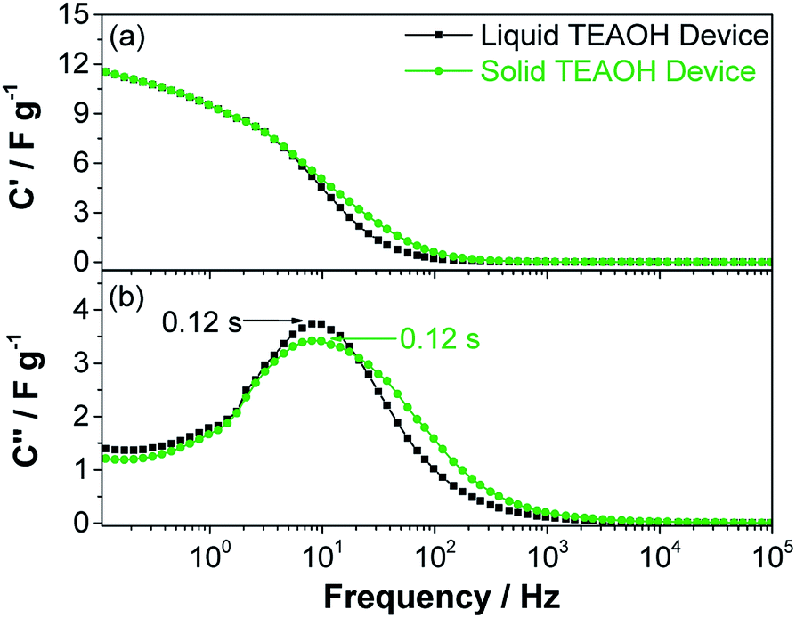 | ||
| Fig. 7 (a) Real capacitance and (b) imaginary capacitance of EDLC devices using liquid 0.5 M TEAOH separator electrolyte and solid TEAOH–PAM(75–25) electrolyte. | ||
The devices were further tested using cyclic voltammetry. Fig. 8a–c show the CVs of typical liquid and solid devices, which revealed near rectangular profiles at lower scan rates and deviated from this ideal CV profile at 5 V s−1. The capacitance of the liquid and solid devices as a function of scan rate is shown in Fig. 8d. Both the liquid and solid devices maintained a relatively stable capacitance greater than ca. 10 F g−1 at scan rates below 1 V s−1 which decreased to ca. 6 F g−1 at 10 V s−1. This drop in capacitance was likely a constraint of the narrow pores in the MWCNT,44 an effect that was observed independent of the electrolyte, demonstrating that TEAOH–PAM does not limit the charge storage of the device. The similarity between the liquid and solid devices in both ac and dc characterizations show that the solid devices enabled by TEAOH–PAM can perform as well as their liquid counterparts.
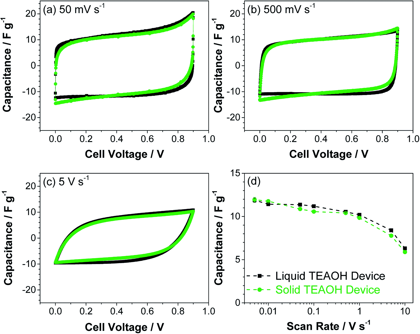 | ||
| Fig. 8 Cyclic voltammetry of liquid and solid EDLC devices at (a) 50 mV s−1, (b) 500 mV s−1, and (c) 500 mV s−1 scan rates; (d) the capacitance at increasing scan rates calculated from CVs. | ||
To evaluate the cycle-life of the ECs, the liquid and solid devices were subjected to charge–discharge cycles at a constant current of 5 mA for 10000 times and the results are shown in Fig. 9. The charge–discharge curves at the end of the cycle-life test (inset) are symmetrical in shape, indicating that both liquid and solid devices were functional. However, the solid device retained close to 100% of its original capacitance, while the liquid cell showed only 75% retention. Furthermore, EIS measurements of the liquid and solid devices were performed before and after cycling (see Fig. S3 in ESI file†). The ESR of the liquid device increased from 1.9 to 4.2 Ω over the course of the cycling, whereas the impedance of the solid device essentially overlapped, and the ESR remained at 1.1 Ω after cycling. The longer cycle-life of the solid device is the result of the superior ability to uptake and retain water by the TEAOH–PAM electrolyte. Accordingly, the TEAOH–PAM polymer electrolyte not only achieved equal or better performance than the liquid TEAOH electrolyte, but also offers the benefits of other practical advantages of a solid device such as safety, light-weight, and a small form factor.
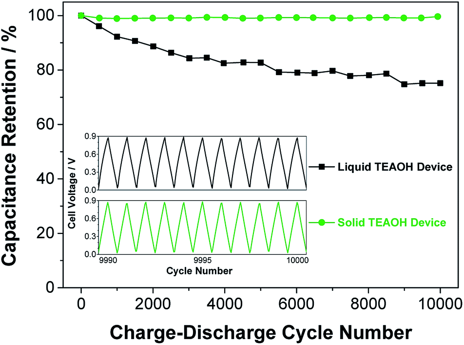 | ||
| Fig. 9 Capacitance retention of liquid and solid EDLC devices after charge–discharge cycling at 5 mA for 10000 cycles. The inset shows the last 10 charge–discharge cycles. | ||
Conclusions
In this study, an OH− ion-conducting polymer electrolyte system based on TEAOH–PAM was developed. The optimized solid electrolyte exhibited outstanding ionic conductivity in the hydrated condition and excellent stability in an ambient environment. A systematic investigation of TEAOH–PAM revealed a stable amorphous structure under different RH conditions and a higher degree of hydration compared to its constituent parts. The stronger water retention of TEAOH–PAM over PAM film suggested increased hydrogen bonding in TEAOH–PAM. A synergy between TEAOH and PAM was revealed by IR studies that showed slight hydrolysis of the PAM functional group by TEAOH, introducing extra hydrophilic carboxylate ions. As a result, the improved level of hydration and the structural stability of TEAOH–PAM promoted fast and steady OH− ion-conduction. These findings will help to effectively design and engineer next generation polymer electrolytes. By leveraging TEAOH–PAM, all-solid EDLC devices were demonstrated, which showed high rate performance (up to 5 V s−1), long cycle-life (10000) with minimal packaging, equalling and outperforming its liquid analogues. This study provides strong evidence for TEAOH–PAM as a promising candidate for EDLC applications and beyond such anion-exchange membranes for fuel cells and solid alkaline-based batteries.
Acknowledgements
We appreciate the financial support from NSERC Canada (Discovery RGPIN-2016-06219 and Discovery Accelerator Supplements 493032). J. Li would also like to acknowledge support from an Ontario Graduate Scholarship (OGS).References
- S. T. Senthilkumar and R. K. Selvan, ChemElectroChem, 2005, 2, 1111–1116 CrossRef.
- L. Nyholm, G. Nyström, A. Mihranyan and M. Strømme, Adv. Mater., 2011, 23, 3751–3769 CAS.
- X. Lu, M. Yu, G. Wang, Y. Tong and Y. Li, Energy Environ. Sci., 2014, 7, 2160–2181 Search PubMed.
- Y.-Z. Zhang, Y. Wang, T. Cheng, W.-Y. Lai, H. Pang and W. Huang, Chem. Soc. Rev., 2015, 44, 5181–5199 RSC.
- H. Hu, Z. Pei and C. Ye, Energy Storage Materials, 2015, 1, 82–102 CrossRef.
- C. Wang and G. G. Wallace, Electrochim. Acta, 2015, 175, 87–95 CrossRef CAS.
- M. Armand and J.-M. Tarascon, Nature, 2008, 451, 652–657 CrossRef CAS PubMed.
- Y. Wang and W.-H. Zhong, ChemElectroChem, 2015, 2, 22–36 CrossRef CAS.
- V. Di Noto, S. Lavina, G. A. Giffin and E. Negro, Electrochim. Acta, 2011, 57, 4–13 CrossRef CAS.
- H. Gao and K. Lian, J. Mater. Chem., 2012, 22, 21272–21278 RSC.
- P. G. Bruce, S. A. Freunberger, L. J. Hardwick and J.-M. Tarascon, Nat. Mater., 2012, 11, 19–29 CrossRef CAS PubMed.
- S. Ketabi, Z. Le and K. Lian, Electrochem. Solid-State Lett., 2012, 15, A19–A22 CrossRef CAS.
- H. Gao and K. Lian, RSC Adv., 2014, 4, 33091–33113 RSC.
- C. Zhong, Y. Deng, W. Hu, J. Qiao, L. Zhang and J. Zhang, Chem. Soc. Rev., 2015, 44, 7484–7539 RSC.
- K. Lian, H. Wu and C. Li, US Pat. 5,585,208, 17 December 1996.
- N. Vassal, E. Salmon and J. F. Fauvarque, J. Electrochem. Soc., 1999, 146, 20–26 CrossRef CAS.
- A. Lewandowski, K. Skorupska and J. Malinska, Solid State Ionics, 2000, 133, 265–271 CrossRef CAS.
- C. C. Yang, J. Power Sources, 2002, 109, 22–31 CrossRef CAS.
- C. C. Yang, S. T. Hsu and W. C. Chien, J. Power Sources, 2005, 152, 303–310 CrossRef CAS.
- N. A. Choudhury, A. K. Shukla, S. Sampath and S. Pitchumani, J. Electrochem. Soc., 2006, 153, A614–A620 CrossRef CAS.
- N. Choudhury, S. Sampath and A. Shukla, Energy Environ. Sci., 2009, 2, 55–67 CAS.
- J. Xie, X. Sun, N. Zhang, K. Xu, M. Zhou and Y. Xie, Nano Energy, 2013, 2, 65–74 CrossRef CAS.
- H. Gao, J. Li and K. Lian, RCS Adv., 2014, 4, 21332–21339 CAS.
- H. Gao, J. Li, J. R. Miller, R. A. Outlaw, S. Butler and K. Lian, Energy Storage Materials, 2016, 4, 66–70 CrossRef.
- J. Li and K. Lian, Polymer, 2016, 99, 140–146 CrossRef CAS.
- L. N. Davis, P. R. Durkin, P. H. Howard and J. Saxena, Investigation of Selected Potential Environmental Contaminants: Acrylamides, Environmental Protection Agency, 1976, vol. 560, 2-76-008 Search PubMed.
- H. Gao and K. Lian, J. Mater. Chem. A, 2016, 4, 9585–9592 CAS.
- P. Yang and P. T. Mather, Thermal Analysis to Determine Various Forms of Water Present in Hydrogels, TA Instruments Application Notes, TA Instruments, 2007 Search PubMed.
- K. Behler, S. Osswald, H. Ye, S. Dimovski and Y. Gogotsi, J. Nanopart. Res., 2006, 8, 615–625 CrossRef CAS.
- B.-H. Park and J.-H. Choi, Electrochim. Acta, 2010, 55, 2888–2893 CrossRef CAS.
- M. A. Vandiver, B. R. Caire, T. P. Pandey, Y. Li, S. Seifert, A. Kusoglu, D. M. Knauss, A. M. Herring and M. W. Liberatore, J. Membr. Sci., 2016, 497, 67–76 CrossRef CAS.
- M. Wiebcke and J. Felsche, Acta Crystallogr., Sect. C: Cryst. Struct. Commun., 2000, 56, 1050–1052 Search PubMed.
- M. Wiebcke and J. Felsche, Microporous Mesoporous Mater., 2001, 43, 289–297 CrossRef CAS.
- S. Jasty, Aldrich Polymer Products Applications and Reference Information, Sigma-Aldrich, 1999, p. 523 Search PubMed.
- E. Bourgeat-Lami, F. Di Renzo, F. Fajula, P. H. Mutin and T. Des Courieres, J. Phys. Chem., 1992, 96, 3807–3811 CrossRef CAS.
- A. Lewandowski, K. Skorupska and J. Malinska, Solid State Ionics, 2000, 133, 265–271 CrossRef CAS.
- M. R. Kraglund, D. Aili, K. Jankova, E. Christensen, Q. Li and J. O. Jensen, J. Electrochem. Soc., 2016, 166, F3125–F3131 CrossRef.
- R. Murugan, S. Mohan and A. Bigotto, J. Korean Phys. Soc., 1998, 32, 505–512 CAS.
- W. Wang, J. Xu and A. Wang, eXPRESS Polym. Lett., 2011, 5, 385–400 CrossRef CAS.
- T. Kolev, M. Spiteller and B. Koleva, Amino Acids, 2010, 38, 45–50 CrossRef CAS PubMed.
- Y. T. Tao, C. Y. Huang, D. R. Chiou and L. J. Chen, Langmuir, 2002, 18, 8400–8406 CrossRef CAS.
- R. LaPorte, Hydrophilic Polymer Coatings for Biomedical Devices, CRC Press LCC, Florida, 1997 Search PubMed.
- P. Taberna, P. Simon and J.-F. Fauvarque, J. Electrochem. Soc., 2003, 150, A292–A300 CrossRef CAS.
- D. Pech, M. Brunet, H. Durou, P. Huang, V. Mochalin, Y. Gogotsi, P.-L. Taberna and P. Simon, Nat. Nanotechnol., 2010, 5, 651–654 CrossRef CAS PubMed.
Footnote |
| † Electronic supplementary information (ESI) available. See DOI: 10.1039/c7se00266a |
| This journal is © The Royal Society of Chemistry 2017 |