Fabrication and characterization of oxide ion conducting films, Zr1−xMxO2−δ (M = Y, Sc) on porous SOFC anodes, prepared by electron beam physical vapor deposition
Tae Ho
Shin†
*a,
Miyoung
Shin†
a,
Geon-Woo
Park‡
b,
Shiwoo
Lee§
b,
Sang-Kuk
Woo
*b and
Jihaeng
Yu
*b
aEnergy Materials Centre, Korea Institute of Ceramic Engineering and Technology, Jinju-si, 52851, Republic of Korea. E-mail: ths@kicet.re.kr
bKorea Institute of Energy Research, Daejeon, 34101, Republic of Korea. E-mail: jhy@kier.re.kr; skwoo@kier.re.kr
First published on 19th January 2017
Abstract
A key obstacle in reducing temperature loss is ohmic loss, which could be lowered by the use of thin electrolytes in electrochemical devices and thus various thin film processing methods have attracted much attention for applications in the SOFC market. Doped stabilized zirconia, Zr1−xMxO2−δ (M = Y, Sc), thin films were successfully deposited on a porous Ni-YSZ substrate via a commercial 10 kW EB-PVD system. The highly conductive and dense Zr1−xMxO2−δ (M = Y, Sc) thin films could be obtained by optimizing the distance (20–40 cm) between the substrate and target, angle (cos![[thin space (1/6-em)]](https://www.rsc.org/images/entities/char_2009.gif) α, α = 0.19π–0.36π) for deposition area and substrate temperature (600–950 °C). Pseudo-cubic phase zirconia, with a preferential crystalline growth (111) and a unique columnar morphology, was observed with a fairly good value of conductivity; ScSZ and YSZ films had conductivities of 0.23 and 0.11 S cm−1 at 900 °C in air. This was achieved on the films which were prepared with proper geometric factors for physical deposition and with a substrate temperature of 950 °C. Finally, the YSZ and ScSZ electrolytes, prepared by EB-PVD, were applied on a solid oxide fuel cell with a Ni-YSZ anode and LSM cathode, which showed 1 W cm−2 of power density under 0.75 V at 900 °C.
α, α = 0.19π–0.36π) for deposition area and substrate temperature (600–950 °C). Pseudo-cubic phase zirconia, with a preferential crystalline growth (111) and a unique columnar morphology, was observed with a fairly good value of conductivity; ScSZ and YSZ films had conductivities of 0.23 and 0.11 S cm−1 at 900 °C in air. This was achieved on the films which were prepared with proper geometric factors for physical deposition and with a substrate temperature of 950 °C. Finally, the YSZ and ScSZ electrolytes, prepared by EB-PVD, were applied on a solid oxide fuel cell with a Ni-YSZ anode and LSM cathode, which showed 1 W cm−2 of power density under 0.75 V at 900 °C.
Introduction
Electrochemical devices that use an oxide-ion conducting ceramic electrolyte, such as solid oxide fuel cells (SOFCs) and solid oxide electrolysis cells (SOEC), have received much attention in the energy sector due to the promise of providing high efficiency, low pollution and fuel flexibility in environmentally friendly power generation and energy storage.1–4 The basic elements of a typical solid oxide electrochemical device consist of an electrolyte sandwiched between a porous anode and porous cathodes. The commercial use of SOFCs, however, has been limited owing to several challenging issues, such as cost, reliability and durability. Thus, thin electrolytes or new materials have been of considerable interest for reducing the operation temperature to allow commercialization of the SOFC generation systems. In particular, one of the most effective strategies is to reduce the thickness of a solid electrolyte since a thin film electrolyte supported on an anode or cathode is preferred to minimize the ohmic loss from the electrolyte.5–12During the past decades, remarkable progress has been made in the field of thin film technology, and some methods, e.g. dip-coating, tape casting, plasma spraying, electrochemical vapor deposition (EVD), sputtering or metal–organic chemical vapor deposition (MOCVD) techniques, have been applied to yttrium stabilized zirconia (YSZ) electrolytes.13–16 Moreover, there has been a growing interest in the synthesis of solid electrolyte films by physical vapor deposition (PVD) due to its strict control of the film microstructure, porosity, stoichiometry and growth rate during the course of the deposition.17–19 Ishihara et al. reported that a cell using a thin LaGaO3 based electrolyte prepared by pulsed laser deposition (PLD) shows excellent cell power generating properties at an intermediate temperature.20 However, despite some positive results being reported, the use of some vacuum deposition processing methods in industrial manufacturing has still been limited due to small deposition coating areas and low productivity.
Since physical vapor deposition by an electron beam (EB-PVD) allows very high deposition rates of up to several 1000 nm s−1, a unique columnar nano-structure in the coating layer, large scale deposition, good adherence to a substrate, and more durable and dense coating layers, EB-PVD has been widely used to fabricate conventional ceramic coating layers such as in the thermal barrier coating (TBC) industry. Another advantage of the conventional process of EB-PVD might be the accomplishment of continuous deposition of the different components and different microstructural layers, such as porous electrodes and dense electrolytes. For instance, the potential usage of EB-PVD to fabricate porous perovskite electrodes and dense solid electrolytes was first discussed in our previous work as a large-scale deposition process for SOFCs.21–23 Therefore, EB-PVD has the potential to be an attractive process not only for thermally and mechanically functional ceramic coatings but also for electrochemical devices including SOFC/ECs as it would be expected to reduce the manufacturing cost due to the above advantages. However, successful SOFC performance with thin layers prepared via EB-PVD is rarely reported, in comparison to TBCs with nano-porous YSZ layers.24,25
In this study, we investigated and optimized Zr1−xMxO2−δ (M = Y, Sc) thin electrolytes with various microstructures using an industrial 10 kW EB-PVD system. The electrical and physical properties of the thin YSZ and scandium stabilized zirconia (ScSZ) films made using EB-PVD were evaluated and the power-generating performance of the SOFC was successfully estimated.
Experimental
Preparation of NiO-YSZ cermet substrate for EB-PVD deposition
In order to fabricate an anode cermet substrate for the deposition process, its microstructure and electrical properties were considered. Commercial NiO (Kosoondo Co, Japan) and 8 mol% YSZ (TZ8Y, Tosoh Co, Japan) were used as starting materials. To optimize an appropriate porous substrate for the deposition process, carbon black (CB, L30, LG carbon, Korea) was selected as a pore former for its porosity and pore distribution for the final sintered NiO-YSZ cermet substrate, which was used as an anode for the SOFC. Carbon black, as much as 20 vol%, was also added to the NiO-YSZ mixed powder, which was mixed in a volumetric ratio of 55![[thin space (1/6-em)]](https://www.rsc.org/images/entities/char_2009.gif) :
:![[thin space (1/6-em)]](https://www.rsc.org/images/entities/char_2009.gif) 45, and ball-milled in propanol. The mixture powders were then compacted under a uni-axial pressure of 400 kgf cm−2 to form discs and then sintered at 1200–1400 °C for 3 h under an ambient atmosphere. Finally, the sintered cermets were polished into disks with a diameter of 20 mm and thickness of 1 mm, to be used as substrates for EB-PVD processing.
45, and ball-milled in propanol. The mixture powders were then compacted under a uni-axial pressure of 400 kgf cm−2 to form discs and then sintered at 1200–1400 °C for 3 h under an ambient atmosphere. Finally, the sintered cermets were polished into disks with a diameter of 20 mm and thickness of 1 mm, to be used as substrates for EB-PVD processing.
Thin film deposition procedure via EB-PVD
The coating films were prepared by EB-PVD using 8 mol% YSZ powder (TZ-8YS, Tosoh Co. Japan) as an evaporating source material on the NiO-YSZ cermet substrate. The deposition time and average deposition rate was 25 min and 0.5 μm min−1, respectively. Detailed information on the deposition procedure conditions is listed in Table 1.| Target source | 8 YSZ (8 mol% yttrium) |
| Vacuum | 10−4 to 10−5 Torr |
| Substrate temp. | 600–950 °C |
| Deposition time | 25 min |
| Generating power of electron beam | 3.5 kW |
| Substrate | NiO-YSZ sintered@1400 |
| Average roughness of surface: 0.132 μm | |
| Porosity ca. 20% (before reducing): EB-PVD | |
| Porosity ca. 35% (after reducing) |
Characterization of the electrolyte film prepared by EB-PVD
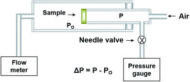
The electrical conductivity of the electrolyte film prepared via EB-PVD on the alumina substrate was estimated using 4-probe DC testing and AC impedance methods. Details of the sample used to measure electrical conductivity are mentioned in our previous work.23 The device used to measure electrical conductivity was assembled and came into contact with Pt paste and Pt wire as the conventional 4-probe unit, using a source-meter unit (K2400, Keithley Instrument, USA) and impedance analyser (SI1260, Schlumberger Technology, UK). The impedance spectra were obtained in the frequency range of 1–106 Hz with an amplitude of 150 mV, and the electrical conductivity was calculated from the resistance in a −50 to +50 μA supply current range. DC conductivity (or AC impedance) of the YSZ film was also examined as a function of oxygen partial pressure in a quartz chamber to confirm its ionic nature.To check the gas tightness of the YSZ film on the porous substrate, the gas permeability was measured using a permeation flux measuring setup, which detects the change in the pressure difference with leakage time as shown in Fig. 1. To estimate the resistance of gas permeability (Rp; Rp = Q/Δp), where Q is the gas leakage flux (cm3 s−1), of the YSZ film on the porous Ni-YSZ cermet prepared by EB-PVD, it could be assumed that the total resistance of gas permeability is the sum of the YSZ film and porous substrate, and it can be expressed as: Rp(YSZ) = Rp(total) − Rp(substrate).26,27 In order to measure Rp (substrate) for the porous Ni-YSZ anode cermet, the specimens had to be reduced at 800 °C in 5% H2 gas to make a porous Ni-YSZ anode from the NiO-YSZ cermet substrate.
In order to measure the power generating performance, a La(Sr)MnO3 cathode was prepared by slurry painting synthesized powder onto deposited electrolyte films and the cathode was then fired at 1100 °C for 2 h in air. The performance of the unit cell, La(Sr)MnO3|Zr1−xMxO2−δ (M = Y, Sc) film|NiO-YSZ, was tested in humidified H2 and air gas which were used as the fuel and oxidant with a rate of 100 ml min−1, respectively. Four platinum lead wires were used as current collectors. An electrical I–V curve and impedance curves at various frequencies (105 to 10−1 Hz) were obtained using a Solartron 1280 potentiostat/frequency response analyser.
Results and discussion
Microstructure controlled thin YSZ film prepared by EB-PVD
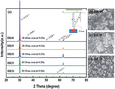
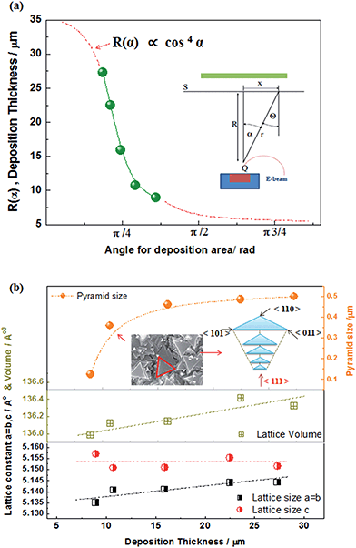
To optimize the thin film on the NiO-YSZ substrate, Zr1−xMxO2−δ (M = Y, Sc) films (ca. 10–20 μm in thickness) were deposited at a substrate temperature of 800 °C under various geometric deposition factors, at various substrate positions with a certain distance (R) and angle (α) from the evaporation source in the vacuum chamber for EB-PVD. X-ray diffraction patterns indicated that the deposited YSZ had a fluorite structure and showed preferential orientation to the (111) plane of the cubic or tetragonal lattice regardless of the deposition distance as shown in Fig. 2(a). The surface morphologies, shown in Fig. 2(b)–(d), have a unique triangle pyramid-shape and the deposition thickness results aligned closely with the cosine law in the kinetic theory of evaporated gases. The pyramid-shape has a tangled morphology at low cosine angles and its size increased with film growth. The deposition thickness as a function of the cosine geometric factor could be predicted well with the cosine law as shown in Fig. 3(a), and corresponded theoretically with the Knudsen cosine law as follows: | (1) |
The EB-PVD method is ideal for the formation of unique columnar microstructures including nano polycrystalline structures.30–33 As shown in Fig. 2(b), the YSZ film is composed of many pyramid-shaped grains, aligned in the (111) plane, grown perpendicular to the interface resulting in a vertical columnar structure. The pyramid shape size on the surface did not linearly increase with the growth of the film. With the growth of the YSZ film, the lattice parameter changed slightly but the lattice parameter indicated a pseudo-cubic YSZ phase including a partially tetragonal phase. It should be noted that different lattice parameters in the pseudo-tetragonal shape might be explained by a strong alignment of grains in the (111) direction; the shorter (311) plane might be considered to be due to the distortion or tilting of the structure.32 In any case, a highly oriented stabilized zirconia film suitable for electrochemical applications with a thickness of ca. 10–20 μm could be fabricated with proper cosine geometric conditions (ca. 25 < R < 35 cm, cos![[thin space (1/6-em)]](https://www.rsc.org/images/entities/char_2009.gif) α: π/4 < α < π/2) under the same deposition rate (ca. 1000 nm min−1 with 3.5 kW electron beam power).
α: π/4 < α < π/2) under the same deposition rate (ca. 1000 nm min−1 with 3.5 kW electron beam power).
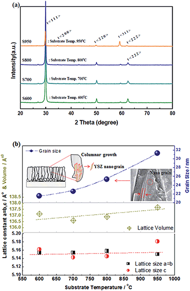
To evaluate the effectiveness of EB-PVD for the fabrication of a dense solid electrolyte and porous electrode coating layer, the stabilized zirconia films, Zr1−xMxO2−δ (M = Y, Sc), were prepared at various substrate temperature conditions with the same deposition rate and geometric factor; a thickness of ca. 10–20 μm was obtained on the porous substrate, a NiO-YSZ anode support. Fig. 4(a) shows the XRD patterns of the YSZ film with different substrate temperatures of 600, 700, 800, and 950 °C, during the deposition process. All of the films show a pseudo-cubic stabilized zirconia phase, suggesting a lattice parameter relation with temperature, as shown in Fig. 4(b), and preferential orientation with (111) crystalline planes, with an anisotropic crystallographic texture being commonly observed. At higher substrate temperatures, other high index planes such as (311) were clearly observed, which might be explained based on competition between strain energy and surface free energy due to different surface mobilities with various substrate temperatures and deposition process parameters.30,31,34 Consistent with the results of different surface mobilities with various substrate temperatures, grain growth and microstructure changes are indicated; columnar growth, which might include polycrystalline nanograins, and grain size, as estimated using the Scherrer equation,35,36 was linearly increased with increasing substrate temperature as shown in Fig. 4(b).
 | (2) |
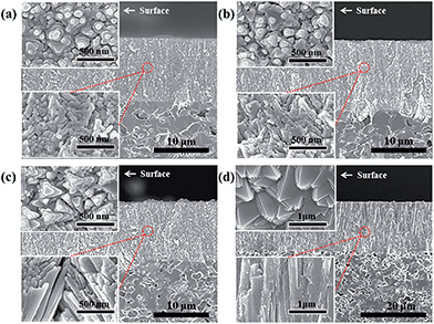
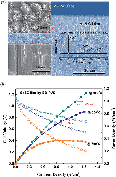
This could be similarly confirmed in Fig. 5 by SEM analysis of the S600, S700, S800 and S950 samples, which are YSZ films on the porous NiO-YSZ cermet prepared under substrate temperatures of 600, 700, 800 and 950 °C, respectively. At higher substrate temperatures, larger grain sizes and pyramid shapes were observed; more dense films suitable for the solid electrolyte were obtained with the S950 (YSZ film) sample as shown in Fig. 5(d). In the case of the ScSZ films under the S950 conditions (ScSZ film), a similar microstructure and single phase were observed. The electrochemical properties of both dense films, YSZ and ScSZ, under the S950 conditions will be discussed in detail later in this paper.
Electrical conductivity of the thin Zr1−xMxO2−δ film prepared by EB-PVD
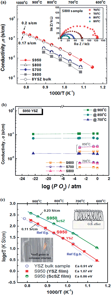
The electrical conductivity of the thin films prepared via EB-PVD and the YSZ bulk sample were investigated by AC impedance analysis and the DC 4-probe method. The electrical conductivity of the S950 (YSZ) sample shows slightly higher conductivity than YSZ bulk as a reference sample; ca. 0.2 S cm−1 was achieved at 1000 °C as shown in Fig. 6(a). However, other films, prepared at lower substrate temperatures, had lower conductivity, suggesting that the porous microstructures of S600, S700, and S800, corresponding with the SEM images in Fig. 5, influenced conductivity. Fig. 6(b) reveals pure oxide ion conduction in the YSZ films for low values of PO2, because the total conductivity is mainly determined by the oxide ion conductivity and is independent of the oxygen partial pressure. To precisely measure the electrical properties, samples on both porous NiO-YSZ (ca. 20% porosity) and alumina substrate (ca. 15% porosity) were prepared at the same time with the same microstructure film on alumina, and were measured for AC impedance. This measurement was also performed separately on the alumina substrate both with and without films and it could be confirmed that the effect of the substrate on the electrical conductivity measurements was negligible in agreement with D. Perez-Coll et al.'s similar work.33As shown in Fig. 6(a), the impedance plots showed only one semicircle in the high frequency region at higher temperatures, similar to the SOFC operating temperature range, which might be attributed to the bulk oxide ion conduction rather than the grain boundary behavior. This suggests that there is no serious nanograin boundary effect or anisotropic crystalline effect from the unique columnar microstructure. However, as shown in Fig. 6(c), the Arrhenius representation of the total conductivity in air for the YSZ and ScSZ films and the YSZ pellet shows that the activation energy of the YSZ film was slightly higher than that of the bulk and the slope of the plot was slightly increased, in particular at the lower temperature range (<700 °C). This suggests that the thin film samples are considerably affected by the grain boundary effect as the activation energy of 1.07 eV indicates an approximate grain boundary value of 1.0 ± 0.1 eV.37 Conductivity at lower temperatures would be more affected by the nano-metric grain size in the columnar structure and anisotropic crystalline growth (111) film, if it were measured at lower temperatures (<400 °C), because the columnar microstructure consists of nano-metric small grains and a different oxygen mobility is apparent in different grain directions. According to the microstructure results in Fig. 4, it might be that grain growth with higher substrate temperatures is associated with lower porosity and the smaller grain boundary effect improves the electrical properties. A detailed analysis of the films as a function of their preferential orientation and nano-grain size effects is now being studied, and the results will be reported in the future.
Gas tightness of the YSZ film for the SOFC electrolyte
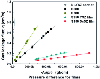
The gas tightness of the films was evaluated, and the change in pressure difference between the testing systems with gas leakage flux is illustrated in Fig. 7. This was evaluated according to Darcy's law: Q = −kAΔp/δ, where Q is the gas leakage flux (cm3 s−1); A is the area of the film (cm2); Δp is the pressure difference (gf cm−2); δ is the thickness of the sample (cm); k is the gas permeability coefficient of the sample (cm4 gf−1 s−1). Generally, the TBC layer prepared by EB-PVD has nanogaps and pores in the columnar grain boundaries, which would be the cause of gas leakage in the YSZ films.32 However, in the case of the films prepared at a substrate temperature of 950 °C, the permeability coefficients suitable for the SOFC electrolyte were 3.67 × 10⁻⁵ and 2.45 × 10⁻⁵ cm4 N−1 s−1 on the YSZ and ScSZ films, respectively. These values are sufficiently less than 1.0 × 10⁻⁴ cm4 N−1 s−1, which has been revealed as the critical value of gas permeability for the YSZ electrolyte layer that is required for SOFCs.25,38 This suggests that nanopores within feather-like, small grains in the columnar structure have insignificant influence on the gas tightness because of their closed-pore shape.32Cell performance of the Zr1−xMxO2−δ film prepared by EB-PVD
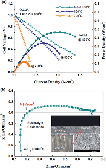
Fig. 8(a) shows the temperature dependent current–power-density (I–P) and current–terminal voltage (I–V) curves of a cell with a YSZ film (ca. thickness of 15 μm) prepared via EB-PVD at a substrate temperature of 950 °C. Although the maximum power density was measured as being around 0.3 W cm−2 at 800 °C, the open circuit voltage (O.C.V) of the cell was 1.007 V initially and the O.C.V degraded to 0.99 V at 800 °C. It should be noted that this degraded O.C.V value, lower than the initial one, might be explained by tiny gas leakage on the YSZ film due to poor sealing or an un-optimized gas tightness of the YSZ film prepared via EB-PVD. If there were insufficient gastight nano-gaps between the columnar structures in the YSZ films, they might easily widen and gas leakage would occur over time. Consequently, the performance degradation at a temperature of 800 °C is shown in Fig. 8(a). Impedance analysis was conducted to further estimate the internal resistance of the cell. Fig. 8(b) shows the impedance spectrum of the cell with a thin YSZ film prepared via EB-PVD under open circuit conditions. The impedance spectrum consists of at least two semicircles, the ohmic and polarization resistances, which could be assigned to the activation and diffusion overpotential, which might be dominated by anodic performance. The value of ohmic resistance (Rs) was 0.2 Ω cm2, which is higher than the theoretical value (0.03 Ω cm2 at 800 °C), considering the conductivity of the film in Fig. 6(a) (σ ≈ 0.05 Ω−1 cm at 800 °C, Rohmic = thickness/(σ × area)), thereby suggesting that gas sealing might be not sufficient in the anode part.To better confirm the practicality of the films prepared by EB-PVD in SOFC applications, an ScSZ film (S950 (ScSZ) sample) was also employed on the optimized anode substrate as an electrolyte for the SOFC cell test due to its higher conductivity and better gas tightness in comparison to the YSZ films (see above), thereby good cell performance could be expected. As previously stated, a similar microstructure and film quality of ScSZ compared to YSZ was obtained by the same EB-PVD processing as shown in Fig. 9(a); dense columnar structures including nanograins and preferential orientation to the (111) crystalline plane were seen in the ScSZ films. In addition, evidently, the ScSZ film (ca. thickness of 15 μm) fabricated via EB-PVD shows excellent electrochemical performance as an electrolyte on NiO-YSZ cermet as shown in Fig. 9(b). Although the I–V curve was not measured beyond a 2 A cm−2 current range due to limitations in the amount of current that could be drawn, a maximum power density would be close to 1.0 W cm−2 at 800 °C if a load of 5 A had been applied, according to the trend of the measured I–V curve. The O.C.Vs of the cell at 700, 800, and 900 °C were 1.15, 1.14, and 1.12 V, respectively, which were close to the theoretical value obtained from the Nernst equation, suggesting that the ScSZ film has significant gas tightness for SOFCs. Particularly, a power density of ca. 1 W cm−2 under 0.75 V was achieved in H2 at 900 °C. In order to assign the electrochemical properties, further detailed experiments will be required; however, in this study, the thin stabilized zirconia film prepared via EB-PVD achieved approximately 0.8 W cm−1 with 0.68 V at 800 °C, a fairly good power performance. The Zr1−xMxO2−δ film, prepared to control the microstructure by EB-PVD, is promising as a thin solid electrolyte for SOFCs with high performance, which is a significant advantage in vacuum deposition processing for electrochemical devices.
Conclusions
The most important consideration thus far for a solid electrolyte is decreasing the ohmic resistance by controlling the microstructure, and also the material composition. For this purpose, a reliable thin electrolyte film on a durable support is required. In this study, we have reported the fabrication of improved and easily controlled thin electrolytes, Zr1−xMxO2−δ (M = Y, Sc), on porous SOFC anodes via EB-PVD processing. Thin films of stabilized zirconia were deposited on porous anode supports and alumina by optimized EB-PVD processing to control the morphology. XRD analysis confirmed the pseudo-cubic phase zirconia with a preferred crystal growth (111) and a unique columnar morphology. SEM analysis revealed suitable dense films for SOFC applications and a thickness of 20 μm, prepared at a substrate temperature of 950 °C. On the other hand, the thin films deposited with other deposition parameters have porous structures and unique morphologies; thereby this easy-to-control technique is expected to improve the surface activity and triple phase boundary (TBP) length on the electrode. The electrical conductivity of the films was studied in oxidizing and reducing atmospheres. Overall, the thin film fabricated via EB-PVD shows pure ionic conductive behavior and a fairly good value of conductivity was achieved on the films prepared at a substrate temperature of 950 °C with a larger columnar grain size; the ScSZ and YSZ films had conductivities of 0.23 and 0.11 S cm−1 at 900 °C in air, respectively. Moreover, the high power density (>0.8 W cm−2) achieved with the ScSZ films, prepared by EB-PVD, resulted from an improved microstructure and gas tightness. Consequently, this study reveals that thin films prepared via EB-PVD are an attractive option for thin film SOFCs with vacuum processing, and reasonably high power performance is achieved with ScSZ films prepared by EB-PVD.Acknowledgements
This research was supported by a grant from the Fundamental R&D Program (10062222) for Technology of Materials & Components funded by the Ministry of Trade, Industry and Energy, Republic of Korea. We also thank the Korea Institute for Advancement of Technology (KIAT) through the Encouragement Program (R0004515) for The Industries of Economic Cooperation Region and KICET internal program (KPP16001).Notes and references
- N. Q. Minh, Solid oxide fuel cell technology-features and applications, Solid State Ionics, 2004, 174, 271–277 CrossRef CAS.
- S. C. Singhal, Solid oxide fuel cells for stationary, mobile, and military applications, Solid State Ionics, 2002, 152–153, 405–410 CrossRef CAS.
- T. Ishihara, Fuel Cells And Hydrogen Energy, in Perovskite Oxide for Solid Oxide Fuel Cells, ed. N. P. Bansal, Springer, New York, 2009 Search PubMed.
- B. C. H. Steele and A. Heinzel, Materials for fuel-cell technologies, Nature, 2001, 414, 345–352 CrossRef CAS PubMed.
- J. Yoon, S. Cho, J.-H. Kim, J. Lee, Z. Bi and A. Serquis, et al., Vertically Aligned Nanocomposite Thin Films as a Cathode/Electrolyte Interface Layer for Thin-Film Solid Oxide Fuel Cells, Adv. Funct. Mater., 2009, 19, 3868–3873 CrossRef CAS.
- B. K. Lai, K. Kerman and S. Ramanathan, On the role of ultra-thin oxide cathode synthesis on the functionality of micro-solid oxide fuel cells: Structure, stress engineering and in situ observation of fuel cell membranes during operation, J. Power Sources, 2010, 195, 5185–5196 CrossRef CAS.
- Y. Takagi, S. Adam and S. Ramanathan, Nanostructured ruthenium – Gadolinia-doped ceria composite anodes for thin film solid oxide fuel cells, J. Power Sources, 2012, 217, 543–553 CrossRef CAS.
- Y. Takagi, K. Kerman, C. Ko and S. Ramanathan, Operational characteristics of thin film solid oxide fuel cells with ruthenium anode in natural gas, J. Power Sources, 2013, 243, 1–9 CrossRef CAS.
- A. Bieberle-Hütter, A. J. Santis-Alvarez, B. Jiang, P. Heeb, T. Maeder and M. Nabavi, et al., Syngas generation from n-butane with an integrated MEMS assembly for gas processing in micro-solid oxide fuel cell systems, Lab Chip, 2012, 12, 4894–4902 RSC.
- A. Evans, A. Bieberle-Hütter, L. J. Bonderer, S. Stuckenholz and L. J. Gauckler, Micro-solid oxide fuel cells using free-standing 3 mol% yttria-stabilised-tetragonal-zirconia-polycrystal electrolyte foils, J. Power Sources, 2011, 196, 10069–10073 CrossRef CAS.
- M. V. F. Schlupp, J. Martynczuk, M. Prestat and L. J. Gauckler, Precursor decomposition, microstructure, and porosity of yttria stabilized zirconia thin films prepared by aerosol-assisted chemical vapor deposition, Adv. Energy Mater., 2013, 3, 375–385 CrossRef CAS.
- W. Jung, J. L. Hertz and H. L. Tuller, Enhanced ionic conductivity and phase meta-stability of nano-sized thin film yttria-doped zirconia (YDZ), Acta Mater., 2009, 57, 1399–1404 CrossRef CAS.
- C.-J. Li, C.-X. Li, Y.-Z. Xing, M. Gao and G.-J. Yang, Influence of YSZ electrolyte thickness on the characteristics of plasma-sprayed cermet supported tubular SOFC, Solid State Ionics, 2006, 177, 2065–2069 CrossRef CAS.
- Y. Jiang, H. Song, J. Gao and G. Meng, Formation and rate processes of Y2O3 stabilized ZrO2 thin films from Zr(DPM)4 and Y(DPM)3 by cold-wall aerosol-assisted MOCVD, J. Electrochem. Soc., 2005, 152, C498–C503 CrossRef CAS.
- M. Liu, J. Gao, D. Dong, X. Liu and G. Meng, Comparative study on the performance of tubular and button cells with YSZ membrane fabricated by a refined particle suspension coating technique, Int. J. Hydrogen Energy, 2010, 35, 10489–10494 CrossRef CAS.
- M. V. F. Schlupp, M. Prestat, J. Martynczuk, J. L. M. Rupp, A. Bieberle-Hütter and L. J. Gauckler, Thin film growth of yttria stabilized zirconia by aerosol assisted chemical vapor deposition, J. Power Sources, 2012, 202, 47–55 CrossRef CAS.
- M. Haydn, K. Ortner, T. Franco, S. Uhlenbruck, N. H. Menzler and D. Stöver, et al., Multi-layer thin-film electrolytes for metal supported solid oxide fuel cells, J. Power Sources, 2014, 256, 52–60 CrossRef CAS.
- A. C. Johnson, A. Baclig, D. V. Harburg, B. K. Lai and S. Ramanathan, Fabrication and electrochemical performance of thin-film solid oxide fuel cells with large area nanostructured membranes, J. Power Sources, 2010, 195, 1149–1155 CrossRef CAS.
- K. Kerman, B. K. Lai and S. Ramanathan, Nanoscale compositionally graded thin-film electrolyte membranes for low-temperature solid oxide fuel cells, Adv. Energy Mater., 2012, 2, 656–661 CrossRef CAS.
- J. Yan, H. Matsumoto, M. Enoki and T. Ishihara, High-Power SOFC Using La0.9Sr0.1Ga0.8Mg0.2O3
![[thin space (1/6-em)]](https://www.rsc.org/images/entities/char_2009.gif) −
−![[thin space (1/6-em)]](https://www.rsc.org/images/entities/char_2009.gif) δ/Ce0.8Sm0.2O2
δ/Ce0.8Sm0.2O2![[thin space (1/6-em)]](https://www.rsc.org/images/entities/char_2009.gif) −
−![[thin space (1/6-em)]](https://www.rsc.org/images/entities/char_2009.gif) δ Composite Film, Electrochem. Solid-State Lett., 2005, 8, A389–A391 CrossRef CAS.
δ Composite Film, Electrochem. Solid-State Lett., 2005, 8, A389–A391 CrossRef CAS. - K. S. Lee, T. H. Shin, S. Lee, S. K. Woo, J. K. Yang and Y. H. Choa, Surface coating of reactive layer with inner nano-pores on lanthanum gallium based oxide, Mater. Sci. Forum, 2005, 161–164 CrossRef CAS.
- T. H. Shin, J. H. Yu, S. Lee, I. S. Han, D. W. Seo and K. S. Hong, et al., Fabrication of YSZ thin-film for SOFC applied by electron beam PVD, Mater. Sci. Forum, 2006, 1114–1117 CrossRef CAS.
- T. H. Shin, J. H. Yu, S. Lee, I. S. Han, S. K. Woo and B. K. Jang, et al., Preparation of YSZ electrolyte for SOFC by electron beam PVD, Key Eng. Mater., 2006, 913–916 CrossRef CAS.
- H. Y. Jung, K.-S. Hong, H. Kim, J.-K. Park, J.-W. Son and J. Kim, et al., Characterization of Thin-Film YSZ Deposited via EB-PVD Technique in Anode-supported SOFCs, J. Electrochem. Soc., 2006, 153, A961–A966 CrossRef CAS.
- X. He, B. Meng, Y. Sun, B. Liu and M. Li, Electron beam physical vapor deposition of YSZ electrolyte coatings for SOFCs, Appl. Surf. Sci., 2008, 254, 7159–7164 CrossRef CAS.
- T. Ide, T. Namikawa and Y. Yamazaki, Preparation of 8 YSZ Films on Porous LSM Substate by Electron Beam Evaporation, Denki Kagaku, 1995, 64, 681–682 Search PubMed.
- C.-J. Li, X.-J. Ning and C.-X. Li, Effect of densification processes on the properties of plasma-sprayed YSZ electrolyte coatings for solid oxide fuel cells, Surf. Coat. Technol., 2005, 190, 60–64 CrossRef CAS.
- D. Chaleix, P. Choquet, A. Bessaudou, L. Frugier and J. Machet, A spatial distribution study of a beam vapour emitted by electron-beam-heated evaporation sources, J. Phys. D: Appl. Phys., 1996, 29, 218 CrossRef CAS.
- C. P. Malhotra, R. L. Mahajan and W. S. Sampath, High Knudsen Number Physical Vapor Deposition: Predicting Deposition Rates and Uniformity, J. Heat Transfer, 2006, 129, 1546–1553 CrossRef.
- K. Wada, N. Yamaguchi and H. Matsubara, Crystallographic texture evolution in ZrO2–Y2O3 layers produced by electron beam physical vapor deposition, Surf. Coat. Technol., 2004, 184, 55–62 CrossRef CAS.
- D. E. Wolfe, J. Singh, R. A. Miller, J. I. Eldridge and D.-M. Zhu, Tailored microstructure of EB-PVD 8YSZ thermal barrier coatings with low thermal conductivity and high thermal reflectivity for turbine applications, Surf. Coat. Technol., 2005, 190, 132–149 CrossRef CAS.
- T. Kato, K. Matsumoto, H. Matsubara, Y. Ishiwata, H. Saka and T. Hirayama, et al., Transmission electron microscopy characterization of a Yttria-stabilized zirconia coating fabricated by electron beam–physical vapor deposition, Surf. Coat. Technol., 2005, 194, 16–23 CrossRef CAS.
- D. Perez-Coll, E. Cespedes, A. J. Dos santos-Garcia, G. C. Mather and C. Prieto, Electrical properties of nanometric CGO-thin films prepared by electron-beam physical vapour deposition, J. Mater. Chem. A, 2014, 2, 7410–7420 CAS.
- S. C. Tjong and H. Chen, Nanocrystalline materials and coatings, Mater. Sci. Eng., R, 2004, 45, 1–88 CrossRef.
- T. H. Shin, Y. Okamoto, S. Ida and T. Ishihara, Self-recovery of pd nanoparticles that were dispersed over La(Sr)Fe(Mn)O3 for intelligent oxide anodes of solid-oxide fuel cells, Chem.–Eur. J., 2012, 18, 11695–11702 CrossRef CAS PubMed.
- A. L. Patterson, The Scherrer Formula for X-Ray Particle Size Determination, Phys. Rev., 1939, 56, 978–982 CrossRef CAS.
- H. L. Tuller, Ionic conduction in nanocrystalline materials, Solid State Ionics, 2000, 131, 143–157 CrossRef CAS.
- C.-J. Li, C.-X. Li and X.-J. Ning, Performance of YSZ electrolyte layer deposited by atmospheric plasma spraying for cermet-supported tubular SOFC, Vacuum, 2004, 73, 699–703 CrossRef CAS.
Footnotes |
| † These authors contributed equally to this work. |
| ‡ Current affiliation: Hyosung Co. |
| § Current affiliation: National Energy Technology Laboratory, Department of Energy. |
| This journal is © The Royal Society of Chemistry 2017 |

