
 Open Access Article
 This Open Access Article is licensed under a Creative Commons Attribution-Non Commercial 3.0 Unported Licence
Enhancing charge mobilities in organic semiconductors by selective fluorination: a design approach based on a quantum mechanical perspective†
Buddhadev
Maiti‡
 a,
Alexander
Schubert‡
ab,
Sunandan
Sarkar
a,
Srijana
Bhandari
a,
Kunlun
Wang
a,
Zhe
Li
a,
Eitan
Geva
*b,
Robert J.
Twieg
*a and
Barry D.
Dunietz
*a
a,
Alexander
Schubert‡
ab,
Sunandan
Sarkar
a,
Srijana
Bhandari
a,
Kunlun
Wang
a,
Zhe
Li
a,
Eitan
Geva
*b,
Robert J.
Twieg
*a and
Barry D.
Dunietz
*a
aDepartment of Chemistry and Biochemistry, Kent State University, Kent, OH 44242, USA. E-mail: twieg@kent.edu; bdunietz@kent.edu; rtwieg@kent.edu
bDepartment of Chemistry, University of Michigan, Ann Arbor, MI 48109, USA. E-mail: eitan@umich.edu
First published on 14th August 2017
Abstract
Selective fluorination of organic semiconducting molecules is proposed as a means to achieving enhanced hole mobility. Naphthalene is examined here as a root molecular system with fluorination performed at various sites. Our quantum chemical calculations show that selective fluorination can enhance attractive intermolecular interactions while reducing charge trapping. Those observations suggest a design principle whereby fluorination is utilized for achieving high charge mobilities in the crystalline form. The utility of this design principle is demonstrated through an application to perylene, which is an important building block of organic semiconducting materials. We also show that a quantum mechanical perspective of nuclear degrees of freedom is crucial for a reliable description of charge transport.
Organic semiconducting materials have received much attention over the last two decades due to their potential optoelectronic applications, such as organic field-effect transistors (OFETs),1–3 organic photovoltaics (OPV),4–7 organic light emitting diodes (OLEDs)8–11 and sensors.12–14 Charge mobility plays a crucial role in determining device performance.15–18 Hence, enhancing charge mobility in organic semiconducting materials is expected to improve device functionality.19,20
In this paper, we investigate utilizing selective fluorination of conjugated organic molecules as a way of enhancing charge mobilities in organic semiconducting materials.21 Fluorinated organic molecules have been previously employed as charge transporting materials.22–24 Judicious introduction of polar C–F bonds enhances intermolecular attractive forces, tightening crystal packing, increasing molecular orbital overlap, and thereby affecting the materials optoelectronic properties.25–29 At the same time, fluorination is often associated with forming a molecular dipole moment that increases the propensity for charge trapping inhibiting charge mobility.30–33 Thus, the challenge is to design structures that maximize charge mobilities while minimizing charge trapping. To this end, we consider a strategy where the local polar C–F bonds are arranged so as to give rise to tightly packed crystals despite having vanishing overall molecular dipoles.34–40
Using dimer models,41 charge transport (CT) rate constants are calculated within the framework of Fermi's golden rule (FGR) based on inputs obtained from quantum chemical calculations.42–47 The FGR rate constant is given by:42,48,49
 | (1) |
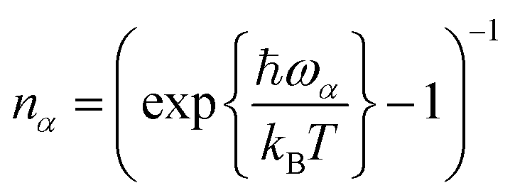 are the normal mode's thermal occupancies. Fexr(t) = exp[−kBTEexrt2/ħ2] accounts for outer-sphere solvation, where Eexr is the corresponding reorganization energy. The inner-sphere reorganization energy is given by
 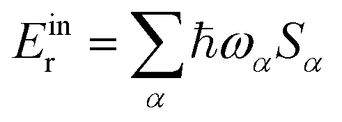 .
.
 | ||
| Fig. 1 A schematic view of the charge donor (blue) and acceptor (red) potential energy surfaces. Er and Ea are the reorganization energy and activation energy, respectively. ΔE is the charge transfer reaction free energy. | ||
The Marcus rate constant can be obtained from the FGR expression in eqn (1) in the high temperature and short time limits:51–54
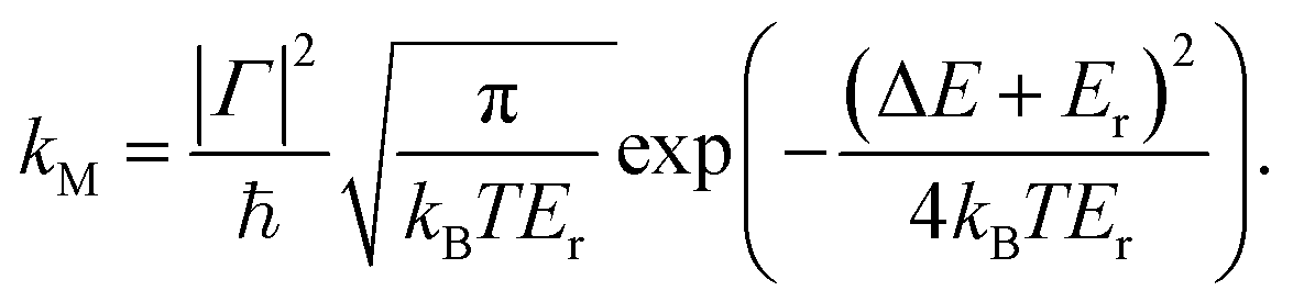 | (2) |
The charge mobility of one-dimensional motion along the molecular stacking axis, η, is evaluated using the Einstein–Smoluchowski equation:55
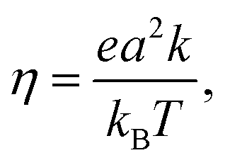 | (3) |
CT rate constants and mobilities were calculated for the following three classes of fluorinated naphthalene molecules (see Fig. 2):
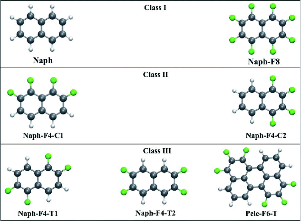 | ||
| Fig. 2 The three classes of molecules under consideration: Class I consists of nonfluorinated and fully fluorinated naphthalenes; Class II, consists of molecules with asymmetric partial fluorination which gives rise to sizable dipole moments; Class III consists of molecules with symmetrical partial fluorination and vanishing dipole moments. | ||
• Class I molecules have vanishing dipole moments56–58 that may result in a herringbone-like arrangement in the crystal phase (see Fig. 3).59 These are represented by the nonfunctionalized naphthalene molecule (Naph) and the fully functionalized molecule octafluoronaphthalene (Naph-F8), which have both been investigated experimentally.60,61 We point out that, while mixtures of Naph/Naph-F8 may form well-packed molecular stacks,61 in this work we consider only crystals of single compounds.
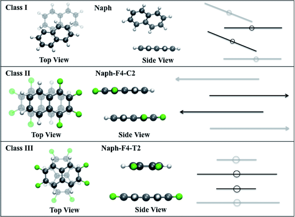 | ||
| Fig. 3 Class I molecules are arranged in a herringbone-like structure, whereas Class II and III molecules are arranged in stacks due to π–π interactions. In Class II the monomers are aligned in alternating directions due to their dipole with an in-plane relative shift. In Class III the molecules show a concentric 90° relative in-plane rotation about the stacking axis. | ||
• Class II molecules include polar C–F bonds that are arranged to produce large molecular dipole moments. The substantial attractive dipole–dipole intermolecular interaction is expected to lead to tightly packed crystals.34–37 These are represented by the partially functionalized 1,2,7,8- and 1,2,3,4-tetrafluoronaphthalene molecules (Naph-F4-C1 and Naph-F4-C2, respectively). While Naph-F4-C1 has not been synthesized (to the best of our knowledge), the Naph-F4-C2 crystals were indeed observed to be tightly packed with a partial facial overlap (see Fig. 3).34
• Class III molecules include polar C–F bonds that are arranged to eliminate the molecular dipole moment. Despite of this, substantial attractive intermolecular stacking interactions between those molecules38–40 give rise to tightly packed crystals (see Fig. 3). These are represented by the partially functionalized 1,2,5,6- and 2,3,6,7-tetrafluoronaphthalene (Naph-F4-T1 and Naph-F4-T2, respectively). Another molecule of this category considered below, is the fluorinated perylene molecule (Pele-F6-T) with a larger conjugated system and a potential to be used in actual optoelectronic applications. To the best of our knowledge, experimental insights into the crystal structure of Class III molecules are not yet available (not reported in the Cambridge Crystallographic Data Centre, CCDC). The Pele-F6-T molecule is currently targeted by our experimental efforts.
We analyze these molecules using a first-principles approach based on density functional theory (DFT) calculations. The range-separated hybrid (RSH) functional62 ωB97X-D63 was employed. This RSH functional addresses well the tendency of local-density-approximation (LDA)-based functionals to underestimate the orbital fundamental gap,64–68 and accounts for dispersion interactions.69 It should be noted that the ωB97X-D functional was shown to yield highly accurate charge reorganization energies with an error of 6.5% in a benchmark study of similar molecules.70 The polarizable continuum solvation model (PCM) was used to account for interactions with the solid-state host.68,71,72 Optimal geometries were generated with the 6-31G(d) basis set. To confirm basis set convergence, we compare the 6-31G(d)-based results for Naph-F4-T2 with results obtained with the larger cc-pVTZ basis set (see Table 1).
| Cl. | Molecule | ε H [eV] | ε L [eV] | IP [eV] | EA [eV] | μ [D] | Q xx [D Å] | Q yy [D Å] | Q zz [D Å] | a [Å] | F inter [eV] | Γ h [eV] | E h,dr [eV] | E h,mr [eV] |
|---|---|---|---|---|---|---|---|---|---|---|---|---|---|---|
| 6-31G(d) | ||||||||||||||
| I | Naph | −7.73 | 0.84 | 7.75 | −0.81 | 0.00 | −62.5 | −50.2 | −49.6 | 5.00 | −0.337 | 0.001 | 0.266 | 0.236 |
| Naph-F8 | −8.38 | −0.11 | 8.32 | 0.22 | 0.00 | −99.8 | −101.1 | −89.3 | 5.99 | −0.264 | 0.005 | 0.545 | 0.458 | |
| II | Naph-F4-C1 | −8.00 | 0.33 | 7.98 | −0.24 | 3.95 | −75.1 | −70.2 | −75.9 | 3.35 | −0.562 | 0.086 | 0.422 | 0.362 |
| Naph-F4-C2 | −8.08 | 0.35 | 8.05 | −0.27 | 2.90 | −75.8 | −75.8 | −70.1 | 3.37 | −0.588 | 0.110 | 0.454 | 0.380 | |
| III | Naph-F4-T1 | −8.03 | 0.27 | 8.00 | −0.20 | 0.00 | −83.5 | −67.1 | −75.8 | 3.51 | −0.563 | 0.380 | 0.424 | 0.394 |
| Naph-F4-T2 | −8.35 | 0.27 | 8.58 | −0.16 | 0.00 | −89.7 | −66.8 | −75.9 | 3.50 | −0.471 | 0.378 | 0.335 | 0.330 | |
| Pele-F6-T | −7.24 | −0.71 | 7.04 | 0.93 | 0.03 | −151.6 | −126.9 | −140.7 | 3.54 | −1.183 | 0.206 | 0.318 | 0.299 | |
![[thin space (1/6-em)]](https://www.rsc.org/images/entities/char_2009.gif) |
||||||||||||||
| cc-pVTZ | ||||||||||||||
| Naph-F4-T2 | −8.57 | 0.03 | 8.72 | −0.15 | 0.00 | −92.0 | −68.0 | −76.7 | 3.50 | −0.437 | 0.363 | 0.331 | 0.311 | |
Electronic coupling coefficients were calculated using a dimer model at the level of configuration interaction with constrained density functional theory (CDFT-CI).73 In the CDFT-CI calculations, each molecule within the ionic dimer is assigned to be either a donor or an acceptor. The two states involved in the CI calculations are then obtained by localizing the charge on one of the molecules M in the ionic dimer calculations. Cation calculations, based on the states M+–M and M–M+, are used for determining the coupling strength associated with hole mobilities and anion calculations (M−–M/M–M−) for electron mobilities, respectively.
HRFs {Sα} were calculated using the DUSHIN program.74,75 Displacement geometries were calculated by comparing the optimized geometries of the neutral (M) and the charged monomer (M+). Normal mode frequencies and eigenvectors were obtained using the optimized neutral monomer M. The validity of the harmonic approximation was confirmed by the very good agreement of reorganization energies evaluated using the HRFs with their direct evaluation (see ESI, Table 2†).
Key electronic structure parameters calculated for Class I, Class II, and Class III molecules are shown in Table 1. We confirm that physically relevant Frontier orbital energies, i.e. energies of the highest occupied and lowest unoccupied molecular orbitals, HOMO (H) and LUMO (L), are typically within 0.1 eV of the calculated ionization potential (IP) and the electron affinity (EA), respectively.68,76 The dipole and quadrupole moments of the different molecules are also provided. As expected, while the molecular dipole moments of Class I and Class III molecules vanish, Class II molecules have substantial dipole moments (3.95 D and 2.90 D). The quadrupole moments of the naphthalene derivatives are observed to increase with the number of fluorine atoms.
The intermolecular separation a for Class I molecules corresponds to the distance between the molecular centers of mass (c.o.m.), and for Class II and III molecules it is set to the distance between the molecular planes. While the intermolecular energies and distances are calculated using the relatively simplified dimer model, we find that the calculated distances are in good agreement with measured crystal structure when available. (In the case of the known compounds Naph, Naph-F8, and Naph-F4-C2, the root mean square deviation (RMSD) of reported crystal structures are 0.134, 0.447, and 0.060 Å, respectively.34,36,60,61) The intermolecular binding energies Finter of Class I molecules are small with values of up to 0.34 eV, whereas for Class II and III molecules, they are in the range of 0.43–0.59 eV.
In Class II molecules, the intermolecular interactions result in a head-to-tail arrangement that aligns the dipole moments of neighboring molecules in the stack at opposite directions, thereby forming a partial facial overlap, see Fig. 3, middle panel. For Naph-F4-C2, this arrangement is coupled with a lateral displacement of the molecules along the long molecular axis. This shift is in agreement with reported crystal structure and DFT calculations performed on the crystal34,36 RMSD between the resolved crystal structure and the calculated dimer structure of Naph-F4-C2 is only 0.06 Å).
In Class III molecules, a relative in-plane rotation, depending on the overall planar symmetry group, is predicted to enable optimal facial overlap in the stacked structure, see Fig. 3, lower panel. Finally, for the Pele-F6-T molecule, the larger conjugation plane yields an interaction energy of 1.2 eV, which is significantly larger than those found for the naphthalene-based molecules. For this molecule a slight twisting deformation is predicted, induced by H–F interactions.
Electronic couplings for hole transfer, Γh, and the corresponding inner sphere reorganization energies, Eh,mr and Eh,dr, calculated using monomer and dimer models,§ respectively, are listed in Table 1. Class III molecules exhibit the largest electronic coupling for hole transport, ∼0.2–0.4 eV. Interestingly, the electronic coupling values for electron transport are all small (≲0.01 eV) except for the case of the larger perylene derivative, where it is 0.11 eV (see ESI, Table 1†). In the following, we will therefore address mobilities for hole transport, unless noted otherwise.
The electronic coupling trends can be understood by considering the relevant orbitals, since coupling values extracted directly from the orbital energies follow the same trend as the couplings obtained via CDFT-CI.73,77 (Orbitals and orbital energies for all molecules considered in this work can be found in the ESI, Fig. 2–8†). Here, we restrict the discussion to the representative cases of Naph-F4-C2 (Class II) and Naph-F4-T2 (Class III), shown in Fig. 4.
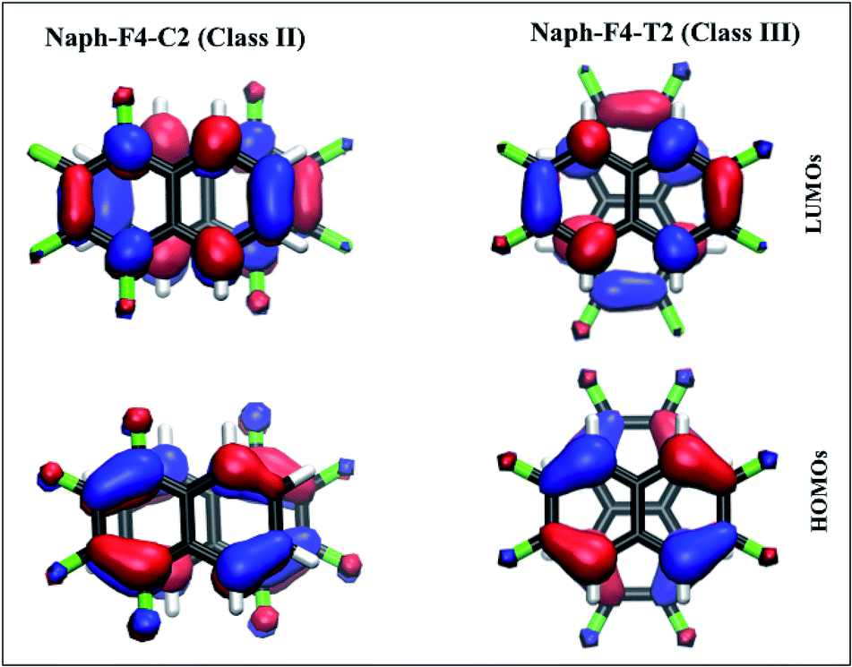 | ||
| Fig. 4 The dimer orbitals for Naph-F4-C2 (left) and Naph-F4-T2 (right) correspond to a superposition of the monomer Frontier orbitals. Significantly larger overlap between lobes from the HOMOs (lower panels) than for the LUMOs (upper panels) results in an enhanced hole mobility over electron mobilities. The in-plane rotation in Class III molecules (lower right panel) maintains a cofacial arrangement and yields a significantly increased monomer-HOMO overlap as compared to the laterally shifted Class II molecules (lower left panel). | ||
In both cases, the obtained dimer HOMOs, lower panels, (LUMOs, upper panels) resemble a linear combination of two monomer HOMOs (LUMOs). The pair of monomer HOMOs feature substantial overlap within the stacked dimer models, whereas the overlap integral within the pair of LUMOs is either weak (for Class II) or vanishing due to symmetry (for Class III). This can be traced back to the H lobes being oriented along the shifting/rotating direction, whereas L lobes point in the perpendicular direction. Consequently, the dimer state energy splitting between states formed by a superposition of two monomer HOMOs, which serves as a measure for hole coupling, is significantly larger than the dimer state L/L+1 splitting, which serves as a measure for electron coupling, for all naphthalene cases. In the larger perylene-based molecule, on the other hand, mixed orbital lobe orientations occur in the monomer HOMO (see Fig. 5(d)) as well as in the LUMO. Thus, significant splitting related to hole and electron coupling appears, indicating potential ambipolar transport properties.
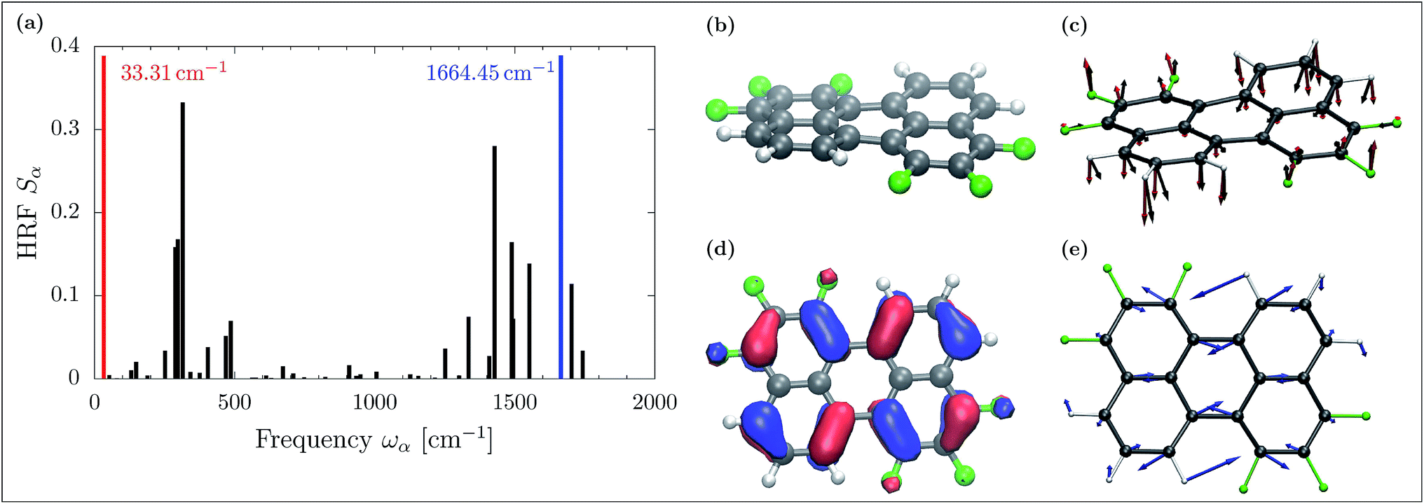 | ||
| Fig. 5 (a) The Huang–Rhys factors (HRFs) for hole transport in the Pele-F6-T molecule. (b) Fluorination causes an out-of-plane deformation in the Pele-F6-T monomer. (c) Removing an electron from the system relieves that stress, resulting in an relaxation displacement (black), which coincides with the lowest frequency normal mode of frequency 33.31 cm−1 (red). (d) The monomer HOMO is depopulated during the charge transport, causing elongation and contraction of bonds. (e) This movement corresponds to a high frequency normal mode of 1664.45 cm−1. | ||
The larger hole coupling in Class III molecules relative to Class II molecules can be traced back to the displacement of the monomers with respect to each other: expectedly, the lateral displacement in Class II molecules, leads to a loss of the monomer HOMOs overlap as indicated in Fig. 4, lower left panel. This shift yields a smaller splitting between the H and H−1 dimer orbitals.30,78 In contrast, the concentric rotation in Class III molecules achieves an overlap between the two HOMOs, shown in Fig. 4, lower right panel, which is twice as large as in the shifted arrangements. Here the quadrupole–quadrupole attractive interactions appear to be the driving force for maintaining facial overlap. Finally, we stress that in all cases, electronic coupling values are sensitive to the intermolecular arrangement and thus to static and dynamic disorder effects.47,79 Further analysis of the electronic coupling trends and their disorder sensitivity is provided in the ESI.†
The reorganization energies Er as listed in Table 1 are within the range of 0.2–0.6 eV. Reorganization energies calculated using ionic dimer CDFT models are reproduced rather well by the simpler ionic monomer models, within 0.1 eV in all cases. We therefore proceed to calculate displacement geometries and HRFs using monomer models.
CT is dominated by modes with large HRFs. The HRFs for Pele-F6-T are presented in panel (a) of Fig. 5 (the HRFs for naphthalene-based molecules and illustration of the key modes are provided in the ESI Fig. 9 and 10,† respectively). The dominant low frequency modes originate from the fluorination-induced bay region distortion, resulting in a slight twist of about 10.5° in the otherwise flat perylene molecule as shown in panel (b) of Fig. 5. Removing an electron from the monomer during hole transport, partially relieves that stress, initiating a twisting motion shown in panel (c), black arrows, which essentially coincides with the low frequency normal mode of 31.31 cm−1 (red). Such dominant low frequency modes do not appear in the smaller and more rigid naphthalene-based molecules without bay regions.
The high frequency normal mode of 1664.45 cm−1 provides the dominant contribution to Einr. Similar to the cases of the naphthalene molecules, such modes are caused by a slightly deformed C![[double bond, length as m-dash]](https://www.rsc.org/images/entities/char_e001.gif) C stretch along the longitudinal molecular axis. This in-plane mode is illustrated with blue arrows in panel (e) of Fig. 5. Its dominant contribution to hole transport can be understood in terms of molecular orbitals: depopulating the HOMO, depicted in Fig. 5 panel (d), yields weakened π bonds, whereas bonds of low HOMO density contract.
C stretch along the longitudinal molecular axis. This in-plane mode is illustrated with blue arrows in panel (e) of Fig. 5. Its dominant contribution to hole transport can be understood in terms of molecular orbitals: depopulating the HOMO, depicted in Fig. 5 panel (d), yields weakened π bonds, whereas bonds of low HOMO density contract.
Hole transport FGR rate constants and hole mobilities, as well as their values at the semi-classical Marcus limit obtained at T = 300 K (ref. 80 and 81) are presented in Table 2. Comparison of the FGR rate constants to their Marcus limit reveals that while the Marcus rate constants follow a similar trend, they are one to two orders of magnitude smaller than the FGR rate constants. This emphasizes the deficiency of Marcus theory43,79,82 in describing charge transfer (and transport) processes. An important finding of our work is that even in the case of charge transport, where the vanishing reaction free energy guarantees a setting in the Marcus-normal region, nuclear quantum effects should not be neglected.
| Molecule | k M [s−1] | η M [cm2 V−1 s−1] | k FGR [s−1] | η FGR [cm2 V−1 s−1] |
|---|---|---|---|---|
| 6-31G(d) | ||||
| Naph | 5.52 × 10⁸ | 0.5 × 10⁻⁴ | 2.49 × 10¹⁰ | 0.0024 |
| Naph-F8 | 4.75 × 10⁹ | 0.6 × 10⁻³ | 1.48 × 10¹¹ | 0.0205 |
| Naph-F4-C1 | 4.05 × 10¹² | 0.18 | 8.46 × 10¹³ | 3.67 |
| Naph-F4-C2 | 5.21 × 10¹² | 0.23 | 1.10 × 10¹⁴ | 4.83 |
| Naph-F4-T1 | 5.46 × 10¹³ | 2.60 | 1.16 × 10¹⁵ | 55.3 |
| Naph-F4-T2 | 1.17 × 10¹⁴ | 5.54 | 2.14 × 10¹⁵ | 101 |
| Pele-F6-T | 4.81 × 10¹³ | 2.33 | 5.55 × 10¹⁴ | 26.9 |
|
||||
| cc-pVTZ | ||||
| Naph-F4-T2 | 1.37 × 10¹⁴ | 6.49 | 2.20 × 10¹⁵ | 104.23 |
For estimating the transport rates we have to consider also the external reorganization. However, the outer sphere reorganization energy is unknown for most of the molecules considered here. External reorganization energies are expected to be about a tenth of the internal reorganization energies due to the predominant contribution of low frequency modes.83 Below, we adopted the naphthalene crystal outer-sphere reorganization energy, Eexr = 35 meV, from ref. 84, for all compounds. An analysis of the rate constant sensitivity with respect to Eexr can be found in the ESI, Tables 3 and 4,† revealing only marginal influence. We point out that similar values for the Eexr have been reported for other oligoacenes.84–86 Larger values of up to 300 meV have been found in few cases and only in the context of photoinduced backbone distortions, e.g. intermolecular torsional or shifting motions,87,88 which are not expected to occur in the case of charge transport.
Class I molecules show the lowest charge mobilities, which can be traced back to the loose packing and weak coupling. Class II molecules exhibit higher mobilities, which can be traced back to the tighter stacking and stronger coupling. However, the shift between adjacent units reduces the monomer-orbital overlap. Class III molecules exhibit the highest mobilities. This can be traced back to the tight stacking and lack of charge traps due to the vanishing dipole moments. In these molecules, a concentric 90° torsion in the cofacial arrangement maintains large orbital overlap between the monomers.
Overall, fluorination may enhance the mobility by more than three to four orders of magnitude in the case of the naphthalene-based molecules. However for Class III molecules, the stronger electronic coupling values implies that the perturbative FGR approach may not be suitable. Strong electronic coupling may lead to delocalization, and thereby to band-like transport that could further enhance mobilities.89,90 We also point out that the diffusive Einstein–Smoluchowski equation, eqn (3), assumes hopping-like transport (although tunneling between adjacent molecules is accounted for.42) In addition, entering the femtosecond regime, transient nuclear non-equilibrium effects might arise, which are not accounted for by the FGR approach used in this work. However, in a recent analysis we find that such transient effects are only of minor influence on the overall transition timescales.91
The molecule Pele-F6-T is predicted to exhibit a hole mobility of about 30 cm2 V−1 s−1. For reference, the calculated mobility in nonfluorinated perylene in herringbone configuration (as in Class I) is 0.07 cm2 V−1 s−1. Thus, fluorination, in the case of the perylene derivative, is seen to enhance the mobility by more than two orders of magnitude. It should be noted that the measured mobilities in perylene are 0.017 cm2 V−1 s−1 (electrons) and 0.02 cm2 V−1 s−1 (holes),92 while even higher electron mobilities (2.0 cm2 V−1 s−1) have been reported under ultrapure conditions.93
In conclusion, the results reported in this paper shed light on the circumstances under which selective fluorination of organic semiconducting molecules can enhance charge mobility. High mobility is found when the functionalization is done so that the overall molecular dipole moment vanishes. The quadrupole, which is the leading electrostatic pole in such cases, can still lead to tight packing, without risking the emergence of charge traps. We also show that while Marcus rates can capture basic trends, they differ quantitatively from the corresponding FGR rates.
Conflicts of interest
There are no conflicts to declare.Acknowledgements
B. D. D. is grateful to support by a NSF-CHEM grant CHE-1362504. E. G. is grateful to support by a NSF-CHEM grant CHE-1464477. B. D. D. and E. G. also acknowledge support from DOE award No. DE-SC0016501. A. S. was awarded an Institute of Complex Adaptive Matter (ICAM) fellowship by the Kent State and University of Michigan ICAM branches. We are also grateful to generous resource allocations on the Ohio Supercomputer Center94 and the Kent State University, College of Arts and Sciences Computing Cluster.References
- G. Horowitz, Adv. Mater., 1998, 10, 365–377 CrossRef CAS.
- M. Malachowski and J. Zmija, Opto-Electron. Rev., 2010, 18, 121–136 CAS.
- Z. Bao, A. J. Lovinger and A. Dodabalapur, Appl. Phys. Lett., 1996, 69, 3066–3068 CrossRef CAS.
- K. M. Pelzer and S. B. Darling, Mol. Syst. Des. Eng., 2016, 1, 10–24 CAS.
- K. Gao, J. Miao, L. Xiao, W. Deng, Y. Kan, T. Liang, C. Wang, F. Huang, J. Peng, Y. Cao, F. Liu, T. P. Russell, H. Wu and X. Peng, Adv. Mater., 2016, 28, 4727–4733 CrossRef CAS PubMed.
- D. M. DeLongchamp, Semiconductor Materials for Solar Photovoltaic Cells, Springer, 2016, pp. 169–196 Search PubMed.
- K. A. Mazzio and C. K. Luscombe, Chem. Soc. Rev., 2015, 44, 78–90 RSC.
- A. Dodabalapur, Solid State Commun., 1997, 102, 259–267 CrossRef CAS.
- S. Reineke, F. Lindner, G. Schwartz, N. Seidler, K. Walzer, B. Lüssem and K. Leo, Nature, 2009, 459, 234–238 CrossRef CAS PubMed.
- S. Lamansky, P. Djurovich, D. Murphy, F. Abdel-Razzaq, H.-E. Lee, C. Adachi, P. E. Burrows, S. R. Forrest and M. E. Thompson, J. Am. Chem. Soc., 2001, 123, 4304–4312 CrossRef CAS PubMed.
- C.-Y. Kuei, W.-L. Tsai, B. Tong, M. Jiao, W.-K. Lee, Y. Chi, C.-C. Wu, S.-H. Liu, G.-H. Lee and P.-T. Chou, Adv. Mater., 2016, 28, 2795–2800 CrossRef CAS PubMed.
- L. E. Kreno, K. Leong, O. K. Farha, M. Allendorf, R. P. Van Duyne and J. T. Hupp, Chem. Rev., 2011, 112, 1105–1125 CrossRef PubMed.
- J. Kong, N. R. Franklin, C. Zhou, M. G. Chapline, S. Peng, K. Cho and H. Dai, Science, 2000, 287, 622–625 CrossRef CAS PubMed.
- B. V. Harbuzaru, A. Corma, F. Rey, P. Atienzar, J. L. Jordá, H. García, D. Ananias, L. D. Carlos and J. Rocha, Angew. Chem., Int. Ed., 2008, 47, 1080–1083 CrossRef CAS PubMed.
- A. Gheno, S. Vedraine, B. Ratier and J. Bouclé, Metals, 2016, 6, 21 CrossRef.
- M. Saliba, S. Orlandi, T. Matsui, S. Aghazada, M. Cavazzini, J.-P. Correa-Baena, P. Gao, R. Scopelliti, E. Mosconi, K.-H. Dahmen, F. De Angelis, A. Abate, A. Hagfeldt, G. Pozzi, M. Graetzel and M. K. Nazeeruddin, Nat. Energy, 2016, 1, 1–7 Search PubMed.
- Z. Yu and L. Sun, Adv. Energy Mater., 2015, 5, 1500213 CrossRef.
- H. Tsuji, K. Sato, Y. Sato and E. Nakamura, J. Mater. Chem., 2009, 19, 3364–3366 RSC.
- J. Halls, C. Walsh, N. Greenham, E. Marseglia, R. Friend, S. Moratti and A. Holmes, Nature, 2000, 376, 498–500 CrossRef.
- C. J. Brabec, C. Winder, M. C. Scharber, N. S. Sariciftci, J. C. Hummelen, M. Svensson and M. R. Andersson, J. Chem. Phys., 2001, 115, 7235–7244 CrossRef CAS.
- J. T. Welch, Selective fluorination in organic and bioorganic chemistry, American Chemical Society, 1991 Search PubMed.
- B. Winkler, F. Meghdadi, S. Tasch, R. Müllner, R. Resel, R. Saf, G. Leising and F. Stelzer, Opt. Mater., 1998, 9, 159 CrossRef CAS.
- Q. Lia, Y. Duana, H.-Z. Gaob, Z.-M. Sua and Y. Genga, J. Mol. Graphics Modell., 2015, 59, 50 CrossRef PubMed.
- J. Calvo-Castro, G. Morris, A. R. Kennedy and C. J. McHugh, Cryst. Growth Des., 2016, 16, 5385 CAS.
- M. Broadhurst, G. Davis, A. DeReggi, S. Roth and R. Collins, Polymer, 1982, 23, 22–28 CrossRef CAS.
- A. Iyer, J. Bjorgaard, T. Anderson and M. E. Köse, Macromolecules, 2012, 45, 6380–6389 CrossRef CAS.
- N. Koch, A. Vollmer, S. Duhm, Y. Sakamoto and T. Suzuki, Adv. Mater., 2007, 19, 112–116 CrossRef CAS.
- E. Di Donato, R. P. Fornari, S. Di Motta, Y. Li, Z. Wang and F. Negri, J. Phys. Chem. B, 2010, 114, 5327–5334 CrossRef CAS PubMed.
- K. Fuchibe, T. Morikawa, K. Shigeno, T. Fujita and J. Ichikawa, Org. Lett., 2015, 17, 1126–1129 CrossRef CAS PubMed.
- V. Coropceanu, J. Cornil, D. A. da Silva Filho, Y. Olivier, R. Silbey and J.-L. Brédas, Chem. Rev., 2007, 107, 926–952 CrossRef CAS PubMed.
- J. H. Yun, S. Park, J. H. Heo, H.-S. Lee, S. Yoon, J. Kang, S. H. Im, H. Kim, W. Lee, B. Kim, J. M. Ko, D. S. Chung and H. J. Son, Chem. Sci., 2016, 6649–6661 RSC.
- O. L. Griffith, X. Liu, J. A. Amonoo, P. I. Djurovich, M. E. Thompson, P. F. Green and S. R. Forrest, Phys. Rev. B: Condens. Matter Mater. Phys., 2015, 92, 085404–085409 CrossRef.
- W.-T. Park, G. Kim, C. Yang, C. Liu and Y.-Y. Noh, Adv. Funct. Mater., 2016, 26, 4695–4703 CrossRef CAS.
- I. Y. Bagryanskaya, Y. V. Gatilov, A. M. Maksimov, V. E. Platonov and A. V. Zibarev, J. Fluorine Chem., 2005, 126, 1281–1287 CrossRef CAS.
- B. W. Gung, X. Xue and H. J. Reich, J. Org. Chem., 2005, 70, 3641–3644 CrossRef CAS PubMed.
- F. Cozzi, S. Bacchi, G. Filippini, T. Pilati and A. Gavezzotti, Chem.–Eur. J., 2007, 13, 7177–7184 CrossRef CAS PubMed.
- S. A. Arnstein and C. D. Sherrill, Phys. Chem. Chem. Phys., 2008, 10, 2646–2655 RSC.
- X.-H. Ju and X. Liao, Int. J. Mater. Res., 2013, 104, 109–113 CrossRef CAS.
- T. Kato and T. Yamabe, J. Chem. Phys., 2004, 121, 2356–2366 CrossRef CAS PubMed.
- D. Kovaček, Z. B. Maksić and I. Novak, J. Phys. Chem. A, 1997, 101, 1147–1154 CrossRef.
- B. Engels and V. Engel, Phys. Chem. Chem. Phys., 2017, 19, 12604–12619 RSC.
- M. H. Lee, B. D. Dunietz and E. Geva, J. Phys. Chem. C, 2013, 117, 23391–23401 CAS.
- M. H. Lee, E. Geva and B. D. Dunietz, J. Phys. Chem. C, 2014, 118, 9780–9789 CAS.
- M. H. Lee, B. D. Dunietz and E. Geva, J. Phys. Chem. Lett., 2014, 5, 3810–3816 CrossRef CAS PubMed.
- A. K. Manna and B. D. Dunietz, J. Chem. Phys., 2014, 141, 121102 CrossRef PubMed.
- D. E. Wilcox, M. H. Lee, M. E. Sykes, A. Niedringhaus, E. Geva, B. D. Dunietz, M. Shtein and J. P. Ogilvie, J. Phys. Chem. Lett., 2015, 6, 569–575 CrossRef CAS PubMed.
- M. H. Lee, E. Geva and B. D. Dunietz, J. Phys. Chem. A, 2016, 120, 2970–2975 CrossRef CAS PubMed.
- J. Jortner, J. Chem. Phys., 1976, 64, 4860–4867 CrossRef CAS.
- A. Nitzan, Chemical Dynamics in Condensed Phases: Relaxation, Transfer and Reactions in Condensed Molecular Systems, Oxford University Press, 2006 Search PubMed.
- K. Huang and A. Rhys, Proc. R. Soc. London, Ser. A, 1950, 204, 406–423 CrossRef CAS.
- R. A. Marcus, J. Chem. Phys., 1956, 24, 966–978 CrossRef CAS.
- R. A. Marcus, J. Chem. Phys., 1956, 24, 979–989 CrossRef CAS.
- R. A. Marcus and N. Sutin, Biochim. Biophys. Acta, 1985, 811, 265–322 CrossRef CAS.
- R. A. Marcus, Rev. Mod. Phys., 1993, 65, 599–610 CrossRef CAS.
- G. L. Hornyak, J. Dutta, H. F. Tibbals and A. Rao, Introduction to nanoscience, CRC Press, 2008 Search PubMed.
- S. Abrahams, J. M. Robertson and J. White, Acta Crystallogr., 1949, 2, 233–238 CrossRef CAS.
- S. Abrahams, J. M. Robertson and J. White, Acta Crystallogr., 1949, 2, 238–244 CrossRef CAS.
- D. Cruickshank, Acta Crystallogr., 1957, 10, 504–508 CrossRef CAS.
- J. Oddershede and S. Larsen, J. Phys. Chem. A, 2004, 108, 1057–1063 CrossRef CAS.
- J. Potenza and D. Mastropaolo, Acta Crystallogr., Sect. B: Struct. Crystallogr. Cryst. Chem., 1975, 31, 2527 CrossRef.
- J. C. Collings, K. P. Roscoe, R. L. Thomas, A. S. Batsanov, L. M. Stimson, J. A. K. Howard and T. B. Marder, New J. Chem., 2001, 25, 1410 RSC.
- R. Baer and D. Neuhauser, Phys. Rev. Lett., 2005, 94, 043002–043004 CrossRef PubMed.
- J.-D. Chai and M. Head-Gordon, Phys. Chem. Chem. Phys., 2008, 10, 6615–6620 RSC.
- E. Livshits and R. Baer, Phys. Chem. Chem. Phys., 2007, 9, 2932–2941 RSC.
- T. Stein, L. Kronik and R. Baer, J. Am. Chem. Soc., 2009, 131, 2818–2820 CrossRef CAS PubMed.
- L. Kronik, T. Stein, S. Refaely-Abramson and R. Baer, J. Chem. Theory Comput., 2012, 8, 1515–1531 CrossRef CAS PubMed.
- H. Phillips, E. Geva and B. D. Dunietz, J. Chem. Theory Comput., 2012, 8, 2661–2668 CrossRef CAS PubMed.
- H. Phillips, Z. Zheng, E. Geva and B. D. Dunietz, Org. Electron., 2014, 15, 1509–1520 CrossRef CAS.
- R. Sure and S. Grimme, J. Chem. Theory Comput., 2015, 11, 3785–3801 CrossRef CAS PubMed.
- C. Bruckner and B. Engels, J. Comput. Chem., 2016, 37, 1335–1344 CrossRef PubMed.
- J. Tomasi, B. Mennucci and R. Cammi, Chem. Rev., 2005, 105, 2999–3094 CrossRef CAS PubMed.
- J.-M. Mewes, Z.-Q. You, M. Wormit, T. Kriesche, J. M. Herbert and A. Dreuw, J. Phys. Chem. A, 2015, 119, 5446–5464 CrossRef CAS PubMed.
- Q. Wu, B. Kaduk and T. Van Voorhis, J. Chem. Phys., 2009, 130, 034109 CrossRef PubMed.
- J. R. Reimers, J. Chem. Phys., 2001, 115, 9103–9109 CrossRef CAS.
- J. Tang, M. T. Lee and S. H. Lin, J. Chem. Phys., 2003, 119, 7188–7196 CrossRef CAS.
- E. J. Baerends, O. V. Gritsenko and R. van Meer, Phys. Chem. Chem. Phys., 2013, 15, 16408–16425 RSC.
- Q. Wu and T. V. Voorhis, J. Chem. Phys., 2006, 125, 164105 CrossRef PubMed.
- J.-L. Brédas, J. P. Calbert, D. A. da Silva Filho and J. Cornil, Proc. Natl. Acad. Sci. U. S. A., 2002, 99, 5804–5809 CrossRef PubMed.
- S. Jang and A. Montoya-Castillo, J. Phys. Chem. B, 2015, 119, 7659–7665 CrossRef CAS PubMed.
- A. Troisi, Adv. Mater., 2007, 19, 2000–2004 CrossRef CAS.
- C. R. Kagan and C. B. Murray, Nature, 2015, 10, 1013–1026 CAS.
- S. Jang and M. D. Newton, J. Phys. Chem. B, 2006, 110, 18996–19003 CrossRef CAS PubMed.
- D. Beljonne, J. Cornil, L. Muccioli, C. Zannoni, J.-L. Brédas and F. Castet, Chem. Mater., 2011, 23, 591–609 CrossRef CAS.
- V. Stehr, R. F. Fink, M. Tafipolski, C. Deibel and B. Engels, WIREs Computational Molecular Science, 2016, 6, 694–720 CrossRef CAS.
- J. E. Norton and J.-L. Brédas, J. Am. Chem. Soc., 2008, 130, 12377–12384 CrossRef CAS PubMed.
- D. P. McMahon and A. Troisi, J. Phys. Chem. Lett., 2010, 1, 941–946 CrossRef CAS.
- V. Lemaur, M. Steel, D. Beljonne, J.-L. Brédas and J. Cornil, J. Am. Chem. Soc., 2005, 127, 6077–6086 CrossRef CAS PubMed.
- R. F. Fink, J. Seibt, V. Engel, M. Renz, M. Kaupp, S. Lochbrunner, H.-M. Zhao, J. Pfister, F. Würthner and B. Engels, J. Am. Chem. Soc., 2008, 130, 12858–12859 CrossRef CAS PubMed.
- F. Ortmann, F. Bechstedt and K. Hannewald, Phys. Rev. B: Condens. Matter Mater. Phys., 2009, 79, 235206 CrossRef.
- S. Jang, J. Chem. Phys., 2011, 135, 034105 CrossRef PubMed.
- X. Sun and E. Geva, J. Chem. Theory Comput., 2016, 12, 2926–2941 CrossRef CAS PubMed.
- Y. Maruyama, T. Kobayashi, H. Inokuchi and S. Iwashima, Mol. Cryst. Liq. Cryst., 1973, 20, 373–380 CrossRef CAS.
- W. Warta, R. Stehle and N. Karl, Appl. Phys. A, 1985, 36, 163–170 CrossRef.
- Ohio Supercomputer Center, http://osc.edu/ark:/19495/f5s1ph73, 1987.
Footnotes |
| † Electronic supplementary information (ESI) available: Reorganization energy, orbital-based coupling energies, HRFs, normal mode motions, transfer rates, and atomic coordinates. See DOI: 10.1039/c7sc02491f |
| ‡ These authors contributed equally to this work. |
§ In the monomer model, DFT energy calculations yield 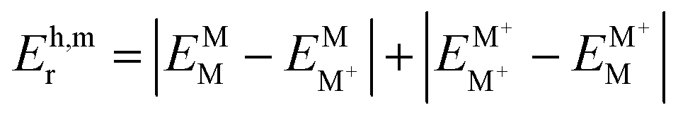 . Here, the superscript denotes the state, and the subscript identifies the geometry. The dimer based . Here, the superscript denotes the state, and the subscript identifies the geometry. The dimer based 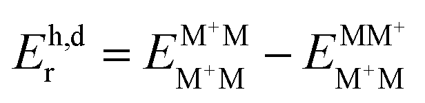 are obtained via CDFT for a cationic dimer state. are obtained via CDFT for a cationic dimer state. |
| This journal is © The Royal Society of Chemistry 2017 |