
 Open Access Article
 This Open Access Article is licensed under a
 Creative Commons Attribution 3.0 Unported Licence
Shaping of porous metal–organic framework granules using mesoporous ρ-alumina as a binder†
Anil H. Valekarab,
Kyung-Ho Choa,
U-Hwang Lee *ab,
Ji Sun Leea,
Ji Woong Yoona,
Young Kyu Hwangab,
Seung Gwan Leec,
Sung June Cho*c and
Jong-San Chang*ad
*ab,
Ji Sun Leea,
Ji Woong Yoona,
Young Kyu Hwangab,
Seung Gwan Leec,
Sung June Cho*c and
Jong-San Chang*ad
aResearch Group for Nanocatalysts, Korea Research Institute of Chemical Technology, Daejeon 305-600, Korea. E-mail: jschang@krict.re.kr; uhwang@krict.re.kr
bDepartment of Green Chemistry, University of Science and Technology (UST), 217 Gajeong-Ro, Yuseong, Daejeon 305-350, Korea
cDepartment of Chemical Engineering, Chonnam National University, Gwangju 500-757, Korea. E-mail: sjcho@chonnam.ac.kr
dDepartments of Chemistry, Sungkyunkwan University, Suwon 440-476, Korea
First published on 8th December 2017
Abstract
The shaping of metal–organic frameworks (MOFs) on a macroscopic level is a vibrant area in MOF research. For practical application of MOFs, the fine microcrystalline powder should be converted into a shaped body while preserving the powder's intrinsic properties. In this study, we prepared millimetre-scale spheres of MIL-100(Fe), MIL-101(Cr), UiO-66(Zr), and UiO-66(Zr)_NH2 using the wet granulation method. The use of mesoporous ρ-alumina (MRA) as a binder resulted in well-shaped MOF bodies which retained their intrinsic properties after shaping. Furthermore, the performance of the MOF spheres was compared to that of compressed pellets in terms of NH3 adsorption using a breakthrough test, and CO2 and N2 adsorption performance was compared using adsorption isotherms at 298 K between the powder and spheres of MOFs for future industrial applications.
1. Introduction
Metal–organic frameworks (MOFs) are a class of promising porous crystalline materials for potential application in gas storage and separation, chemical sensing, heterogeneous catalysis, etc.1–5 They have unique structural and texture characteristics like large surface areas, tunable pore-size distributions, and coordinatively unsaturated metal sites (CUSs).6–8 Over the past decade, many researchers and companies have attempted to find a commercial use for these appealing porous materials.9–12 However, there are several problems that need to be addressed in order to successfully use MOFs for industrial and chemical engineering applications. The fundamental issue with commercial applications is the highly pulverulent property of MOFs. One of the major strategies to overcome this problem has been to produce macroscopic MOF bodies using various shaping processes.Shaped MOF bodies have been produced in the form of pellets, tablets, monoliths, granules, and spheres using typical shaping techniques like pressing, extrusion, granulation, and spray drying.13–17 In general, the shaped body of a porous material provides improved handling, improved bulk density, and reduced pressure drop for fluid flow in packed bed systems. However, the chemical and mechanical sensitivities of MOFs to binders, pressure-shaping process, etc. limit our ability to form them into shaped bodies without losing their novel properties.18,19 Therefore, to understand the pivotal importance of the shaping of MOFs, the prime objective of the current investigation was to develop a facile shaping method using a versatile binder suitable for use with various MOFs while preserving their specific properties.
Recently, new strategies have been reported for fabricating macroscopic MOFs on a millimeter scale. Blom et al. prepared agglomerated spheres of CPO-27(Ni) using hydrocolloids and gelling agents as natural polymer binders by the “molecular gastronomy” method.20 CPO-27(Ni) powder was formed into nicely shaped spheres 2.5–3.5 mm in size and containing more than 84 wt% of MOFs with minor loss in their weight-specific surface area (WSSA); the resulting spheres showed good mechanical strength. In another example, large-scale continuous neat melt-phase synthesis of ZiF-8 under solvent-free or low-solvent conditions was successfully demonstrated by James et al.21 This enhanced extrusion technique provided shaped bodies with high space-time yields (STY) of up to 144 × 103 kg m−3. In the past, several research groups including ours reported the preparation of well-shaped MOFs using polymer, graphite and silica sol binders for a wide range of applications.16,22–28 However, the thermal stability of the shaped MOF bodies decreased owing to the low degradation temperature of the polymer binder. MOFs have also been shaped by deposition onto range of metal surfaces, also with follow-up the addition/coating of binders.29–32
Although most studies have focused on the shaping methods, processes, or application of shaped MOFs, very few studies have investigated the effect of the shaping process on the intrinsic chemical properties of MOFs.33,34 Here, we present a simple but effective granulation process to fabricate macroscopic MOF bodies using amorphous-phase mesoporous ρ-alumina (MRA) as a binder. MRA can be used as hydratable and bondable alumina in the presence of a small amount of a hydrophilic polar dispersion medium like water or alcohol.35,36 The corresponding properties can be potential use for binding MOF particles during the shaping process under ambient condition. Indeed MRA requires no additional additives where all the shaping process can be completed through wet granulation and subsequent drying in ambient air or elevated temperature. In this study, we prepared millimeter-scale spheres of MIL-100(Fe), MIL-101(Cr), UiO-66(Zr), and UiO-66(Zr)_NH2 using the wet granulation method. MRA bonded with the MOFs without the substantial loss of the fundamental properties for example initial sorption capacity of the crystals. Thus, the formation of well-shaped bodies which can be easy-to handle and also is scalable in large amount shown in the present work can be considered as a significant step toward the industrial-scale application and commercial application of MOFs.
2. Results and discussion
2.1. Porous and morphological properties of MRA binder
Fig. 1a and b show the N2 adsorption–desorption isotherms at 77 K and the Barrett–Joyner–Halenda (BJH) pore-size distribution of the alumina binder, respectively. The BET surface area of the alumina binder was 218 m2 g−1. The N2 adsorption–desorption isotherm (Fig. 1a) was type IV, showing a broad hysteresis loop in the relative pressure (p/p0) range of 0.5 to 0.9, which confirms the mesoporosity of MRA. MRA had an average pore diameter of ∼4 nm, which was calculated using the BJH method. The transmission electron microscopy (TEM) image of MRA (inset of Fig. 1b) shows mesopores with a disordered structure, and the pore diameter agrees well with the results of the BJH method. Therefore, the corresponding mesoporous binder is suitable for the shaping of thermally and chemically sensitive MOFs because it compensates for the loss in surface area. It is also useful for the diffusion of gases in adsorption/separation processes.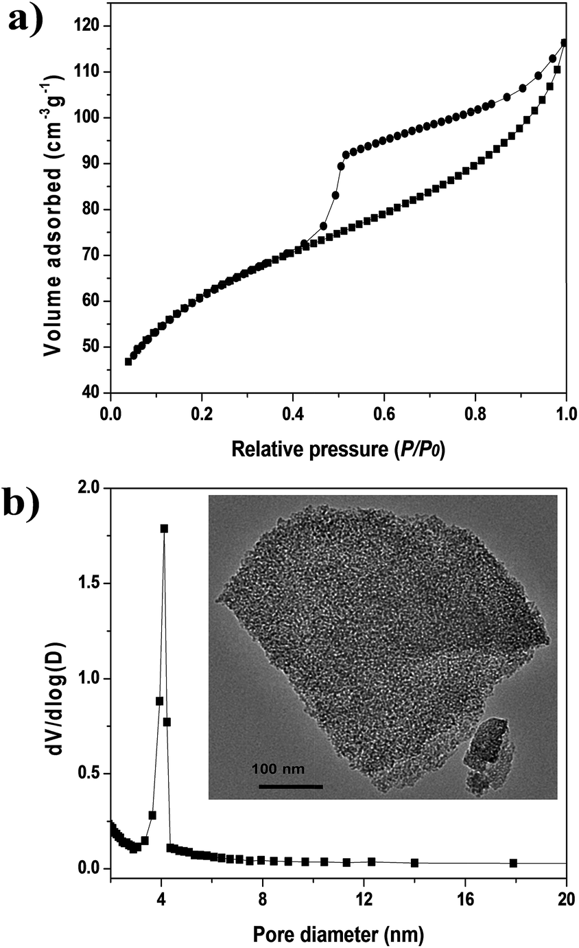 | ||
| Fig. 1 Characterization of MRA binder: (a) N2 adsorption–desorption isotherms at 77 K and (b) pore-size distribution calculated from BJH method (inset of (b) is the TEM image of MRA binder). | ||
2.2. Characterization of shaped MOF bodies
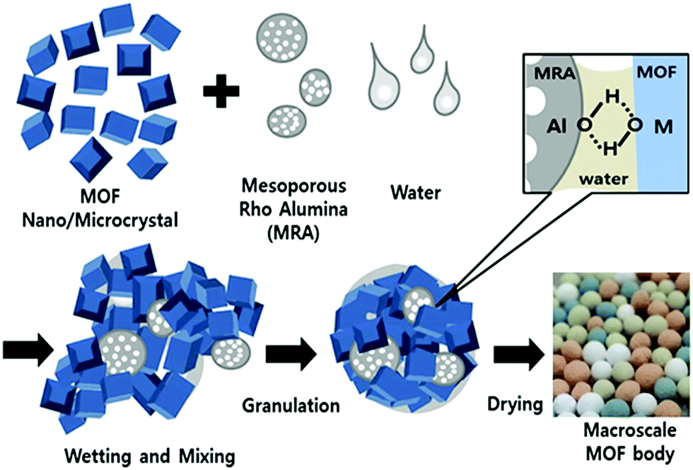 | ||
| Scheme 1 Preparation of MOF granules/spheres through agglomeration of MOF and MRA particles by wet granulation process. | ||
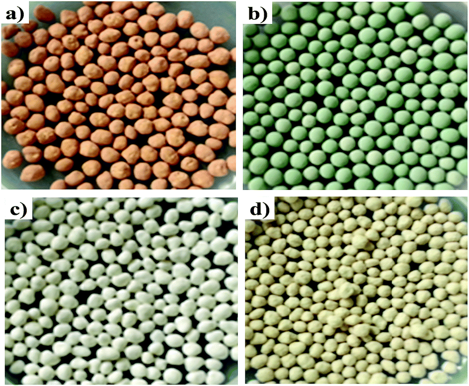 | ||
| Fig. 2 Photographs of shaped bodies containing 5 wt% MRA binder: (a) MIL-100(Fe), (b) MIL-101(Cr), (c) UiO-66(Zr), and (d) UiO-66(Zr)_NH2. | ||
The nitrogen gas adsorption isotherms at 77 K for all the shaped MOF bodies showed a negligible decrease in nitrogen uptake (volume) compared to their pristine powders; however, no change in the isotherm patterns was observed (Fig. 3). Furthermore, the multistep features apparent in the powder samples (Fig. 3a and b) remained unchanged, indicating no alterations in pore dimensions; this was further supported by the pore-size distribution curves presented in Fig. S2.† Mercury porosimetry was used to gain further information on the porous characteristics of the shaped MOFs. The hierarchical pore structures (mesoporosity and macroporosity) obtained from mercury porosimetry for all the MOF spheres because of inter particle voids generated during shaping process (Fig. 4). However, the pore-size distributions of the spheres were dependent on the particle size, shaping process parameters and the interaction and affinity between the spheres and MRA.
 | ||
| Fig. 3 N2 adsorption–desorption isotherms at 77 K for MOFs (powder and sphere containing 5 wt% MRA binder) degassed overnight at 423 K: (a) MIL-100(Fe), (b) MIL-101(Cr), (c) UiO-66(Zr), and (d) UiO-66(Zr)_NH2. | ||
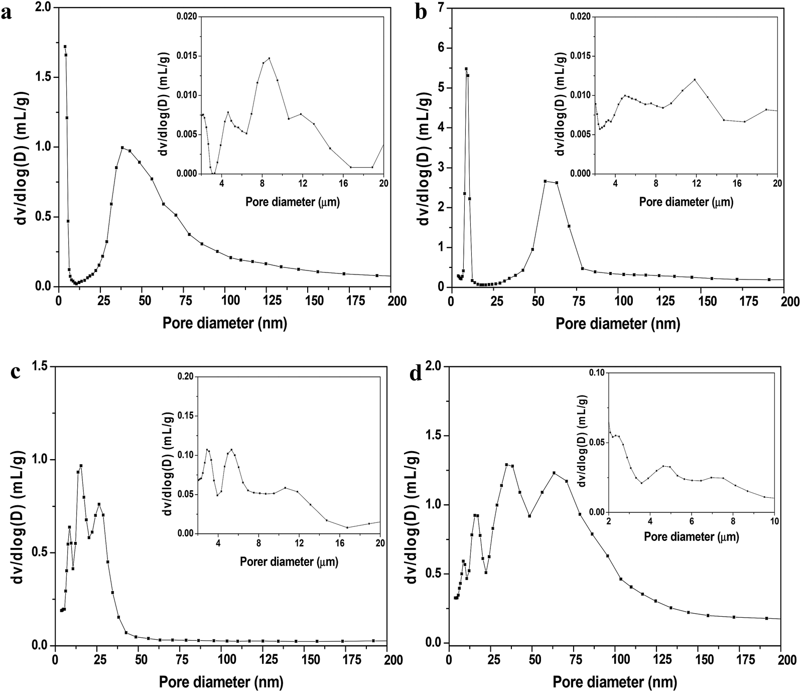 | ||
| Fig. 4 Mesopore- and macropore-size distribution profiles of shaped MOFs were measured by mercury intrusion porosimetry: (a) MIL-100(Fe), (b) MIL-101(Cr), (c) UiO-66(Zr), and (d) UiO-66(Zr)_NH2. Insets show small numbers of macropores in the range of 0.5 to 10 or 20 μm. | ||
The fundamental properties of MOF spheres containing 95 wt% MOF and 5 wt% binder are given in Table 1. The loss in WSSA for all the MOFs were in the range of 1.0–7.7% after shaping into spheres, probably due to difference in the intrinsic properties of the MOFs, the preparation conditions, and the interaction between the MOFs and the MRA binder. The average crushing strengths and bulk densities of spheres were also measured and were found to depend on the physicochemical properties of the MOFs and on a number of adjustable process parameters during granulation.39 The crushing strength of the spheres could be controlled by fine-tuning the binder amount in the spheres. Increasing the concentration of the binder from 5 to 10 wt% improved the crushing strength of the MIL-100(Fe) spheres more than 30%.
| MOF | Surface area (m2 g−1) | Pore volume (cm3 g−1) | Loss in WSSAa after shaping (%) | Average crushing strength (N) | Average sphere density (g cm−3) | ||
|---|---|---|---|---|---|---|---|
| Powder | Sphere | Powder | Sphere | ||||
| a WSSA: weight-specific surface area. | |||||||
| MIL-100(Fe) | 2088 | 1831 | 1.0 | 0.9 | 7.7 | 6.7 | 0.63 |
| MIL-101(Cr) | 4066 | 3685 | 1.6 | 1.6 | 4.6 | 4.1 | 0.57 |
| UIO-66(Zr) | 1050 | 911 | 1.5 | 0.9 | 8.7 | 4.7 | 0.67 |
| UIO-66(Zr)_NH2 | 875 | 823 | 1.6 | 1.0 | 1.0 | 2.5 | 0.56 |
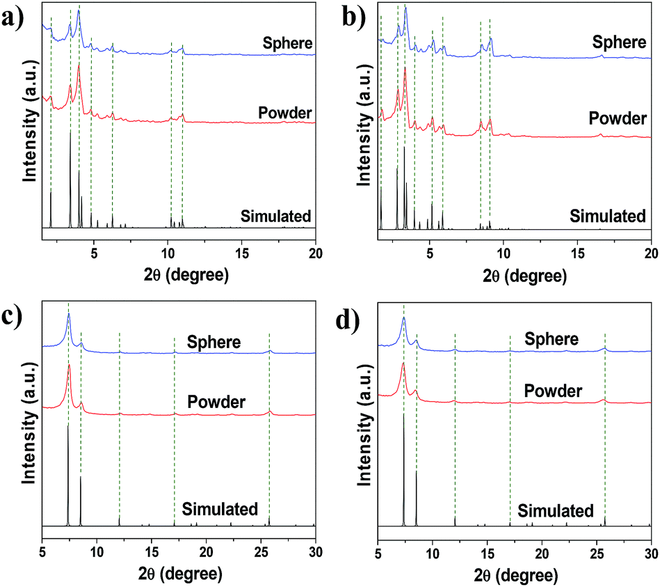 | ||
| Fig. 5 Simulated and experimental XRD patterns of MOF powders and shaped bodies (containing 5 wt% MRA binder): (a) MIL-100(Fe), (b) MIL-101(Cr), (c) UiO-66(Zr), and (d) UiO-66(Zr)–NH2 since, crystallographic information file (CIF) for UiO-66(Zr)–NH2 was not available simulated XRD pattern of parent UiO-66(Zr) was used. | ||
Macroscale shaped bodies were built via the binding of MOF and MRA particles through interaction of hydroxyl groups present on the surfaces of the particles (Scheme 1). The FT-IR spectra of the MIL-100(Fe) shaped bodies with different binder amounts (Fig. 6) showed interfacial binding between the MRA and MOF particles. The vibrational stretching frequencies of the Fe–OH group of MIL-100(Fe) at approximately 3600–3700 cm−1 were generated from the coordination of water or OH groups to Fe3+.46,47 As compared to the original powder, the intensity of the ν(OH) peaks decreased and their peak positions shifted to lower wavenumbers. This fact can be explained in two ways. First, the MOF and MRA particles were mixed and granulated into spheres in the presence of water, leading to intimate interactions through hydrogen bonding. The hydrophilic OH groups promoted initial wetting and good dispersion of the MRA binder on the surfaces of the MOF particles in the presence of polar liquids such as water and alcohol. The OH groups present on the surfaces of the binder particles, along with the dispersion medium, led to strong adhesion and the dipolar attraction of OH groups from the surfaces of adjacent MOF particles to produce intermolecular hydrogen bonding. This solid–solid interfacial hydrogen bonding in the presence of water shifted the peak position to lower wavenumbers in the shaped MIL-100(Fe). Second, the reduced peak intensity is a function of the amount of binder present in the shaped bodies. MRA has a strong affinity for adsorption on oxide particles dispersed in water.35
 | ||
| Fig. 6 FTIR spectra of powder and shaped forms of MIL-100(Fe) with different MRA binder contents: (a) powder MIL-100(Fe), (b) sphere MIL-100(Fe)-5 wt% MRA binder, and (c) sphere MIL-100(Fe)-10 wt% MRA binder. | ||
Recent advances in visualization strategies on a microscale have been utilized in several studies to unlock the inner complexity of materials.48–52 Therefore, in order to obtain some insight into the internal arrangement of MOF crystals and MRA particles, we characterized the shaped bodies using microscopic analysis. SEM analysis of the alumina binder showed a wide range of particle sizes (Fig. S3†), and there were clear-cut differences in the particle sizes of alumina and MOFs. The alumina particles were in the micrometer range, whereas all the MOF particles were in the sub micrometer range. No visible difference in the morphologies of the powder and spherical forms of the MOFs was observed. It was not easy to identify alumina particles in the interior of spheres using SEM, possibly owing to the low alumina concentration and its good dispersion in the spheres. EDS (X-ray energy-dispersive spectroscopy) elemental mapping was used to determine the spatial distribution of elements in the spheres. As shown in Fig. 7a, EDS elemental mapping revealed that alumina particles were distributed uniformly throughout the sphere, even at the higher alumina concentration (20 wt%). The images of the other sample morphologies showed similar results (Fig. S4†). The homogeneity of the binder within the spheres can be explained by the breaking up of agglomerates and the continued exchange of particles during granule growth in the granulation process.39
 | ||
| Fig. 7 (a) Cross-sectional SEM/EDS elemental mapping image of 20 wt% MRA binder in MIL-100(Fe) shaped body and (b) TEM/EDS elemental mapping images of 5 wt% MRA binder in MIL-100(Fe) shaped body. In the images of (a), red areas represent Al from MRA binder. In the image of (a) red area represents Al from MRA binder. In the mapping image of (b), yellow and green areas represent Al from MRA and Fe from MOF respectively. | ||
To provide further insights into the morphological behavior, we performed TEM elemental mapping. Fig. 7b shows that agglomeration of MRA (5 wt%) and MIL-100(Fe) particles occurred when single large MRA binder particles were surrounded by small aggregated particles of MIL-100(Fe). This interparticle interaction between MRA and MOF was the major reason for the formation of mesopores (∼50 nm) and macropores (∼10 μm) in the shaped bodies, as evident from the mercury porosimetry analysis (Fig. 4). Therefore, the agglomeration of MOFs with the present MRA binder particles resulted in additional benefits in the form of a hierarchical pore system.
The NH3-TPD profiles of the MIL-100(Fe) powder and shaped bodies with different MRA concentrations are shown in Fig. 8a. Considering the lower degradation temperature of MIL-100(Fe) (548 K), the TPD temperature was increased from 323 to 573 K with a ramping rate of 5 K min−1. The samples were pretreated at 523 K for 12 h prior to analysis to generate CUSs by removal of the terminal water molecule and the hydroxyl group from the framework and to avoid NH3 adsorption onto physically bonded water through hydrogen bonding.58 The MRA binder plays an important role in determining the properties of the resulting shaped MOF bodies because binder particles can cover the pore windows and active surfaces (such as CUSs) of the MOFs. Indeed, the NH3-TPD profiles of the MIL-100(Fe) powder and the MRA-containing shaped bodies were similar, which indicates that the chemically active sites of MIL-100(Fe) were well preserved in its shaped form.
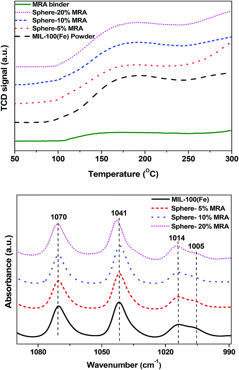 | ||
| Fig. 8 (a) NH3-TPD profiles and (b) pyridine-IR spectra of MIL-100(Fe) powder and spheres with 5, 10, and 20 wt% MRA binder. | ||
To further clarify this phenomenon, we carried out pyridine-IR analysis of the powder and shaped samples of MIL-100(Fe) (Fig. 8b). The pyridine-IR results of MIL-100(Fe) were well summarized in a previous study.46 The Lewis acid sites in MIL-100(Fe) generated from coordination of pyridine with Fe3+ and Fe2+ at 1014 cm−1 and 1005 cm−1, respectively, were retained in the spheres with 5–20% MRA. The presence of Fe2+ in MIL-100(Fe) was generated due to removal of OH or F group from trimeric cluster because of high temperature treatment prior to pyridine-IR analysis [for further details, see the in situ IR study of MIL-100(Fe) in the ESI, Fig. S5†].46 No significant variation in the strength of the peaks was observed. The decrease in the acidity was proportional to the binder content, which can dilute the acidity of MOFs. A similar dilution effect was observed for H-ZSM-5 zeolite by IR and TPD analyses after being shaped into granules using an attapulgite clay binder.59 The aforementioned results confirmed that the CUSs of MIL-100(Fe) were unaffected by the shaping process and the use of MRA binder.
2.3. Ammonia adsorption on shaped bodies of MIL-100(Fe)
Recently, toxic gas adsorption, particularly that of ammonia, over porous solid materials has attracted the attention of many researchers.58,60–62 Considerable effort has been made to choose a potential material for the adsorption of ammonia gas. Bandosz et al. comprehensively studied MIL-100(Fe) and an MIL-100(Fe)-GO composite material for this purpose.58 Considering MIL-100(Fe) as a potential candidate for NH3 adsorption, its practical implementation motivated us to perform NH3 breakthrough tests using shaped bodies of MIL-100(Fe). We also investigated how the binder and shaping method affect the NH3 adsorption performance of MIL-100(Fe). Generally, NH3, with its free lone pair of electrons, tends to bind with electron-deficient species through a coordinative covalent bond. It is well documented that several MOFs, including MIL-100(Fe), have Lewis acidity due to the presence of CUSs.8,63 Therefore, NH3 can easily form coordinate bonds with the CUSs of MIL-100(Fe).The NH3 breakthrough results obtained for granulated and conventional pellets of MIL-100(Fe) are shown in Fig. 9. The test was carried out at 298 K under dry conditions using samples that were pretreated at 423 K for 12 h prior to the breakthrough test. The ammonia uptake capacity of MIL-100(Fe) spheres (4.4 mmol g−1) was higher than that of MIL-100(Fe) pellets (3.6 mmol g−1), which confirms that the pore structure and CUSs of MIL-100(Fe) spheres were not significantly affected by the shaping (granulation) process. The ammonia uptake capacity of MIL-100(Fe) reported here is somewhat higher than that previously reported (4.3 mmol g−1).58 On the other hand, shaping MIL-100(Fe) by pressing affects the crystal structure and porosity (Fig. S6†), which subsequently lowers the adsorption of ammonia as compared to the spheres prepared in the present work. We further checked the effect of pressure-dependent pelletization on the physicochemical properties of MIL-101(Cr) in detail (Fig. S7†), and the obtained results were in line with the results obtained for MIL-100(Fe). Additionally, we have summarized the other shaping strategies utilized previously in the literature for shaping of MOFs and their effects on its porous properties [Table S1†].
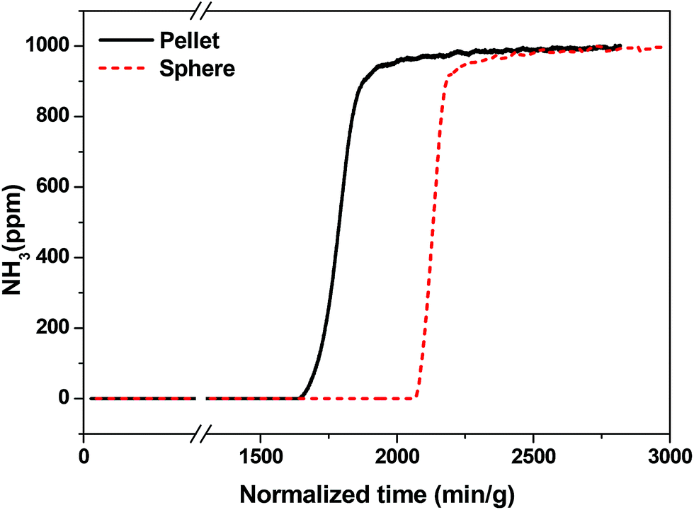 | ||
| Fig. 9 NH3 breakthrough test of shaped MIL-100(Fe) bodies (spheres) containing 5 wt% MRA binder and a pellet fabricated by using the pressing method with 3 wt% of graphite as the binder at 298 K. Amounts of NH3 calculated for sphere (4.4 mmol g−1) and pellet (3.6 mmol g−1) were normalized to the MIL-100(Fe) content present. | ||
2.4. CO2 adsorption on powder and shaped bodies of MIL-101(Cr), UiO-66(Zr) and UiO-66(Zr)_NH2
Metal−organic frameworks (MOFs) have been extensively investigated for the adsorption of CO2.64 In recent years, adsorption-based post combustion CO2 capture has also received great attention.65,66 The adsorbents for this process should have high CO2 uptake at lower pressure (0.15 bar) under ambient temperature such as 298 K, good CO2/N2 selectivity and excellent water stability.64 MOFs have been demonstrated with great potential for this purpose.64 The MOFs reported herein have excellent water stability which allowed us to evaluate their performance in CO2 and N2 capture at low pressure (up to 1 bar).There is minor difference in CO2 adsorbed on the powder with respect to the spheres of MOFs (Fig. 10). This difference in uptakes is in accordance with the difference in surface area of powder and sphere samples (Table 1). MIL-101(Cr) is a very prominent example of MOFs that possess unsaturated metal sites.37,45 It can capture CO2 in its pores through physisorption as well as through a Lewis acid−base interaction between the coordinatively unsaturated Cr(III) sites, and O atoms in CO2 molecule.66 It exhibits high CO2 adsorption capacity at lower pressure (25.9 cm3 g−1), which has not influenced much after shaping into spears (24.5 cm3 g−1). At 0.15 bar pressure UiO-66(Zr)_NH2 adsorb higher CO2 (6.8 cm3 g−1) compared to pristine UiO-66(Zr) (5.4 cm3 g−1). MOFs containing polar functional groups tend to have stronger interactions with CO2 leading to higher adsorption volume.66–68 However, at higher pressure (1 bar), physisorption occurs which leads to almost similar overall CO2 adsorption capacity for UiO-66(Zr)–NH2 and its pristine form (27.4 cm3 g−1). Nevertheless, CO2 adsorption capacity of UiO-66(Zr) and its NH2 functionalized analogs did not change much after shaping into spheres. N2 uptake of powder and spheres of MOFs is almost same. Moreover, CO2/N2 sorption ratios at 1.0 bar were 12, 10.9 and 7 for shaped samples of UiO-66(Zr), UiO-66(Zr)–NH2 and MIL-101(Cr) respectively, which indicating high affinity for CO2 over N2 in all MOF samples tested here. Further research is in progress to evaluate the adsorption behavior of series of gasses over various MRA shaped MOFs bodies. These results strongly imply that physical as well as chemical properties of MOFs (surface area, functionality and CUSs) remain intact after shaping them into spheres using MRA binder.
 | ||
| Fig. 10 CO2 and N2 adsorption isotherms at 298 K for MOFs powder and sphere (containing 5 wt% MRA binder) degassed overnight at 150 °C: (a) UiO-66(Zr), (b) UiO-66(Zr)_NH2, and (c) MIL-101(Cr). | ||
3. Conclusions
We successfully fabricated shaped bodies of MIL-100(Fe), MIL-101(Cr), UiO-66(Zr), and UiO-66(Zr)_NH2 using MRA binder. The MOFs were prepared to have a macroscopic structure on a millimeter scale with small loss of WSSA and increased bulk density. Advanced visualization tools were utilized to unlock the inner complexity of the shaped MOF bodies. It is of interest that the MOF shaped bodies retained their intrinsic properties after shaping, which was confirmed by gas adsorption, NH3-TPD, and pyridine-IR measurements. The possible adverse effect of the binder on the chemical properties of the shaped MOFs was studied in detail in order to determine their potential for practical applications. Additionally, results of an NH3 breakthrough test using MIL-100(Fe) spheres and CO2 adsorption using MIL-101(Cr), UiO-66(Zr) and UiO-66(Zr)_NH2 spheres showed the potential of our shaping method for use in practical applications for MOFs.4. Experimental section
4.1. MOF synthesis
![[thin space (1/6-em)]](https://www.rsc.org/images/entities/char_2009.gif) :0.67BTC:xH2O (x = 55–280). The reactant mixture was heated at 433 K for 12 h using a Teflon-lined pressure vessel. The synthesized solid was filtered and washed with deionized (DI) water. Further washing was carried out with DI water and ethanol at 343 K for 3 h and purified with a 38 mM NH4F solution at 343 K for 3 h. The solid was finally dried overnight at less than 373 K in air.:1:11.6:5.4. The reaction mixture was vigorously stirred to obtain a homogeneous gel. The mixture was then heated to 423 K at a rate of 1 K min−1 and maintained at this temperature for 6 h in the reactor without stirring, leading to a crystalline UiO-66(Zr) solid. The resulting product (∼510 g) was recovered from the slurry by filtration, redispersed in 7 L of DMF at 333 K for 6 h under stirring, and recovered by filtration. The same procedure was repeated twice, using methanol (MeOH) instead of DMF. The solid product was finally dried at 373 K overnight.
:0.67BTC:xH2O (x = 55–280). The reactant mixture was heated at 433 K for 12 h using a Teflon-lined pressure vessel. The synthesized solid was filtered and washed with deionized (DI) water. Further washing was carried out with DI water and ethanol at 343 K for 3 h and purified with a 38 mM NH4F solution at 343 K for 3 h. The solid was finally dried overnight at less than 373 K in air.:1:11.6:5.4. The reaction mixture was vigorously stirred to obtain a homogeneous gel. The mixture was then heated to 423 K at a rate of 1 K min−1 and maintained at this temperature for 6 h in the reactor without stirring, leading to a crystalline UiO-66(Zr) solid. The resulting product (∼510 g) was recovered from the slurry by filtration, redispersed in 7 L of DMF at 333 K for 6 h under stirring, and recovered by filtration. The same procedure was repeated twice, using methanol (MeOH) instead of DMF. The solid product was finally dried at 373 K overnight.4.2. Preparation of MRA binder
Al(OH)3 (7 μm, KC Chemical Corp.) was used as the starting material to prepare mesoporous alumina by the flash pyrolysis method. The preparation method of the alumina binder was reported by Cho and co-workers.35,36 Briefly, Al(OH)3 was pyrolyzed for a few seconds at 800–1000 K in order to obtain flash-calcined alumina. To achieve such a fast dehydration, Al(OH)3 was dropped into a tubular furnace under vigorous vibration that had been preheated to the desired temperature. The powder was collected at the bottom of the furnace. The bulk density of the obtained powder was measured to ensure the flash calcination upon dehydration and subsequently was sealed tightly in polypropylene bottle for further use during the hydration in tubular furnace, Al(OH)3 was converted into mesoporous rehydratable alumina (MRA).4.3. Preparation of spheres and pellets
Spheres of the various MOFs were prepared using the conventional granulation method. In brief, known amounts of MOF powder (for e.g. 10–100 g), MRA binder (5–20 wt% for MOF powder), and dispersion medium (water) were mixed using a hand-made pan-type granulator. During the mixing process, the requisite amount of water was briefly sprayed onto the samples to achieve the desired particle growth. Granules with a wider size distribution were thus produced. After sieving, the granules (2.0–2.5 mm) were rolled using a roller machine to enhance the spherical shape. The samples were then dried from room temperature to 383 K for 12 h in a vacuum oven to remove the water from the spheres.Pellets were prepared by mixing a known amount of MOF powder (50–100 mg) and 3 wt% graphite binder powder. This powder mixture then transferred into a multiple cylindrical dies (diameter 3 mm, length 10 mm) and the dies were closed using a stainless steel dowels. The assembly was pressed in manual hydraulic press to 5000 psi (34 MPa) and held this pressure for 1 min. The prepared pellets were 3.0 mm in diameter and 4.0 mm in length.
4.4. Characterization
Powder X-ray diffraction patterns of all MOF powders and shaped bodies were obtained by a Rigaku diffractometer (D/MAX IIB, 2 kW) using Ni-filtered Cu Kα radiation (40 kV, 30 mA, λ = 1.5406 Å). The N2 adsorption isotherms were measured at 77 K using a Micromeritics Tristar 3000 system. The samples were dehydrated under vacuum at 423 K for 12 h prior to analysis. The specific surface areas were evaluated using the Brunauer–Emmett–Teller (BET) method and the pore volume was determined by the single-point method at p/p0 = 0.99. The macroscale pore-size distribution of the MOF spheres was measured using a mercury porosimeter (Micromeritics, Autopore III 9420). The sphere densities were estimated from the mass and physical dimensions of individual spheres. Ten well-shaped spheres were selected to calculate the average sphere density. The crushing strengths of the spheres and pellets were measured using the strength meter described in our previous paper.22 For each sample, the average crushing strength of at least 10 individual spheres or pellets was considered. The internal cross sections of the spheres were examined to study the distribution of the binder particles, as well as their arrangements with MOF particles, using scanning electron microscopy (SEM) (Tescan Mira 3 LMU FEG with an accelerating voltage of 10 kV) and X-ray energy-dispersive spectroscopy (EDS) (Bruker, Quantax 200 equipped with a Si Drift Detector). Scanning transmission electron microscopy (STEM)-EDS measurements were taken on a FEI Tecnai G2 T20 S microscope with an accelerating voltage of 200 kV. The NH3 temperature-programmed desorption (TPD) profiles of the binders, MOF powders, and spheres were measured on a Micromeritics AutoChem II 2920 V3.05 system equipped with a thermal conductivity detector. Samples were activated at 523 K for 12 h in He flow prior to the adsorption step. Subsequently, the activated samples were exposed to NH3 at 373 K for 1 h at a flow rate of 50 mL min−1. Physically adsorbed NH3 was removed by purging with helium gas at the same temperature for 1 h. TPD data was recorded from 313 to 673 K at a heating rate of 5 K min−1. The Fourier-transform infrared (FT-IR) spectra of adsorbed pyridine (Aldrich, 99.8%) were obtained at room temperature using a Nicolet FT-IR spectrometer (iS50). For this purpose, the MIL-100(Fe) powder was pelletized to a wafer (10 mg cm−2) and evacuated for 2 h at 423 K and 523 K under vacuum (∼10−6 Torr), respectively. After the adsorption of pyridine at room temperature, the adsorbed pyridine was evacuated for 30 min at 298–523 °C, respectively. For temperature-dependent FT-IR analyses, samples were pressed into self-supported wafers and the spectra were recorded at 323 K after evacuation for 2 h under vacuum (∼10−6 Torr) at the same temperature.4.5. Ammonia breakthrough test
To perform the NH3 breakthrough test, ∼0.246 mL of 60–70-mesh-sieved samples was loaded into a 3.96 mm (i.d.) quartz tube reactor. Before the breakthrough test, each sample was activated for 12 h at 423 K under 20 mL min−1 He flow. The concentration of the mixed ammonia/air balanced gas was 1000 ppm and the total flow rate was 43.6 mL min−1. The contact time and linear velocity of the 1000 ppm NH3/air mixture gas penetrating the samples were 0.399 s and 5.9 cm s−1, respectively. During the breakthrough test for ammonia, the concentration of effluent gas was determined using a tunable diode-laser NH3 gas detector. The amount of adsorbed NH3 was calculated by integrating the breakthrough curve for the sample subtracted from the integration of the breakthrough curve for the blank test.4.6. CO2 adsorption
CO2 sorption isotherms of MOFs were measured up to 1 bar using a Micromeritics Tristar 3020 analyzer. Before the measurements, the sample (∼150 mg) was degassed under reduced pressure at 423 K for 12 h. The CO2 adsorption volumes for MOFs at 298 K were then measured.Conflicts of interest
There are no conflicts to declare.Acknowledgements
This work was supported by the Center for Hybrid Interface Materials (HIM) for the Global Frontier R&D Program (2013M3A6B1073298), funded by the Ministry of Science, ICT & Future Planning (MSIP), and the R&D Convergence Program (CRC 14-1-KRICT) of National Research Council of Science & Technology (NST) of the Republic of Korea.References
- J. A. Mason, M. Veenstra and J. R. Long, Chem. Sci., 2014, 5, 32–51 RSC.
- J. R. Li, R. J. Kuppler and H. C. Zhou, Chem. Soc. Rev., 2009, 38, 1477–1504 RSC.
- L. E. Kreno, K. Leong, O. K. Farha, M. Allendorf, R. P. Van Duyne and J. T. Hupp, Chem. Rev., 2012, 112, 1105–1125 CrossRef CAS PubMed.
- J. Liu, L. Chen, H. Cui, J. Zhang, L. Zhang and C. Y. Su, Chem. Soc. Rev., 2014, 43, 6011–6061 RSC.
- A. H. Valekar, K.-H. Cho, S. K. Chitale, D.-Y. Hong, G.-Y. Cha, U.-H. Lee, D. W. Hwang, C. Serre, J.-S. Chang and Y. K. Hwang, Green Chem., 2016, 18, 4542–4552 RSC.
- G. Ferey, Chem. Soc. Rev., 2008, 37, 191–214 RSC.
- M. Eddaoudi, J. Kim, N. Rosi, D. Vodak, J. Wachter, M. O'Keeffe and O. M. Yaghi, Science, 2002, 295, 469–472 CrossRef CAS PubMed.
- D. Y. Hong, Y. K. Hwang, C. Serre, G. Ferey and J. S. Chang, Adv. Funct. Mater., 2009, 19, 1537–1552 CrossRef CAS.
- A. U. Czaja, N. Trukhan and U. Muller, Chem. Soc. Rev., 2009, 38, 1284–1293 RSC.
- N. Stock and S. Biswas, Chem. Rev., 2012, 112, 933–969 CrossRef CAS PubMed.
- Y. K. Seo, J. W. Yoon, J. S. Lee, U. H. Lee, Y. K. Hwang, C. H. Jun, P. Horcajada, C. Serre and J. S. Chang, Microporous Mesoporous Mater., 2012, 157, 137–145 CrossRef CAS.
- F. Ragon, P. Horcajada, H. Chevreau, Y. K. Hwang, U. H. Lee, S. R. Miller, T. Devic, J. S. Chang and C. Serre, Inorg. Chem., 2014, 53, 2491–2500 CrossRef CAS PubMed.
- R. Zacharia, D. Cossement, L. Lafi and R. Chahine, J. Mater. Chem., 2010, 20, 2145–2151 RSC.
- A. M. Ribeiro, M. C. Campo, G. Narin, J. C. Santos, A. Ferreira, J. S. Chang, Y. K. Hwang, Y. K. Seo, U. H. Lee, J. M. Loureiro and A. E. Rodrigues, Sep. Purif. Technol., 2013, 110, 101–111 CrossRef CAS.
- A. F. P. Ferreira, J. C. Santos, M. G. Plaza, N. Lamia, J. M. Loureiro and A. E. Rodrigues, Chem. Eng. J., 2011, 167, 1–12 CrossRef CAS.
- M. G. Plaza, A. M. Ribeiro, A. Ferreira, J. C. Santos, U. H. Lee, J. S. Chang, J. M. Loureiro and A. E. Rodrigues, Sep. Purif. Technol., 2012, 90, 109–119 CrossRef CAS.
- A. Carne-Sanchez, I. Imaz, M. Cano-Sarabia and D. Maspoch, Nat. Chem., 2013, 5, 203–211 CrossRef CAS PubMed.
- Y. H. Hu and L. Zhang, Phys. Rev. B: Condens. Matter Mater. Phys., 2010, 81, 174103–174105 CrossRef.
- K. W. Chapman, G. J. Halder and P. J. Chupas, J. Am. Chem. Soc., 2009, 131, 17546–17547 CrossRef CAS PubMed.
- A. I. Spjelkavik, Aarti, S. Divekar, T. Didriksen and R. Blom, Chem.–Eur. J., 2014, 20, 8973–8978 CAS.
- D. Crawford, J. Casaban, R. Haydon, N. Giri, T. McNally and S. L. James, Chem. Sci., 2015, 6, 1645–1649 RSC.
- P. J. Kim, Y. W. You, H. Park, J. S. Chang, Y. S. Bae, C. H. Lee and J. K. Suh, Chem. Eng. J., 2015, 262, 683–690 CrossRef CAS.
- N. Chanut, A. D. Wiersum, U.-H. Lee, Y. K. Hwang, F. Ragon, H. Chevreau, S. Bourrelly, B. Kuchta, J.-S. Chang, C. Serre and P. L. Llewellyn, Eur. J. Inorg. Chem., 2016, 4416–4423 CrossRef CAS.
- U.-H. Lee, A. H. Valekar, Y. K. Hwang and J.-S. Chang, in The Chemistry of Metal–Organic Frameworks: Synthesis, Characterization, and Applications, ed. S. Kaskel, Wiley-VCH Verlag GmbH & Co. KGaA, Weinheim, Germany, 2016, pp. 551–572 Search PubMed.
- M. A. Moreira, J. C. Santos, A. F. P. Ferreira, J. M. Loureiro, F. Ragon, P. Horcajada, K.-E. Shim, Y.-K. Hwang, U.-H. Lee, J.-S. Chang, C. Serre and A. E. Rodrigues, Langmuir, 2012, 28, 5715–5723 CrossRef CAS PubMed.
- M. Wickenheisser, T. Paul and C. Janiak, Microporous Mesoporous Mater., 2016, 220, 258–269 CrossRef CAS.
- M. Wickenheisser and C. Janiak, Microporous Mesoporous Mater., 2015, 204, 242–250 CrossRef CAS.
- A. Permyakova, O. Skrylnyk, E. Courbon, M. Affram, S. Wang, U.-H. Lee, A. H. Valekar, F. Nouar, G. Mouchaham, T. Devic, G. De Weireld, J.-S. Chang, N. Steunou, M. Frère and C. Serre, ChemSusChem, 2017, 10, 1419–1426 CrossRef CAS PubMed.
- A. Perea-Cachero, J. Dechnik, R. Lahoz, C. Janiak, C. Telleza and J. Coronas, CrystEngComm, 2017, 19, 1470–1478 RSC.
- D. Frohlich, E. Pantatosaki, P. D. Kolokathis, K. Markey, H. Reinsch, M. Baumgartner, M. A. Veen, D. E. De Vos, N. Stock, G. K. Papadopoulos, S. K. Henninger and C. Janiak, J. Mater. Chem. A, 2016, 4, 11859–11869 Search PubMed.
- F. Jeremias, D. Frohlich, C. Janiak and S. K. Henninger, RSC Adv., 2014, 4, 24073–24082 RSC.
- F. Jeremias, S. K. Henninger and C. Janiak, Chem. Commun., 2012, 48, 9708–9710 RSC.
- D. Bazer-Bachi, L. Assie, V. Lecocq, B. Harbuzaru and V. Falk, Powder Technol., 2014, 255, 52–59 CrossRef CAS.
- G. W. Peterson, J. B. DeCoste, T. G. Glover, Y. G. Huang, H. Jasuja and K. S. Walton, Microporous Mesoporous Mater., 2013, 179, 48–53 CrossRef CAS.
- I. J. Jang, H. S. Shin, N. R. Shin, S. H. Kim, S. K. Kim, M. J. Yu and S. J. Cho, Catal. Today, 2012, 185, 198–204 CrossRef CAS.
- H. J. Lee, J. H. Kim, D.-W. Park and S. J. Cho, Appl. Catal., A, 2015, 502, 42–47 CrossRef CAS.
- G. Ferey, C. Mellot-Draznieks, C. Serre, F. Millange, J. Dutour, S. Surble and I. Margiolaki, Science, 2005, 309, 2040–2042 CrossRef CAS PubMed.
- I. T. Cameron, F. Y. Wang, C. D. Immanuel and F. Stepanek, Chem. Eng. Sci., 2005, 60, 3723–3750 CrossRef CAS.
- P. R. Mort, Powder Technol., 2005, 150, 86–103 CrossRef CAS.
- S. M. Iveson, J. D. Litster, K. Hapgood and B. J. Ennis, Powder Technol., 2001, 117, 3–39 CrossRef CAS.
- G. Ferey, C. Serre, C. Mellot-Draznieks, F. Millange, S. Surble, J. Dutour and I. Margiolaki, Angew. Chem., Int. Ed., 2004, 43, 6296–6301 CrossRef CAS PubMed.
- J. H. Cavka, S. Jakobsen, U. Olsbye, N. Guillou, C. Lamberti, S. Bordiga and K. P. Lillerud, J. Am. Chem. Soc., 2008, 130, 13850–13851 CrossRef PubMed.
- M. Kandiah, M. H. Nilsen, S. Usseglio, S. Jakobsen, U. Olsbye, M. Tilset, C. Larabi, E. A. Quadrelli, F. Bonino and K. P. Lillerud, Chem. Mater., 2010, 22, 6632–6640 CrossRef CAS.
- G. K. Reynolds, J. S. Fu, Y. S. Cheong, M. J. Hounslow and A. D. Salman, Chem. Eng. Sci., 2005, 60, 3969–3992 CrossRef CAS.
- Y. K. Hwang, D. Y. Hong, J. S. Chang, S. H. Jhung, Y. K. Seo, J. Kim, A. Vimont, M. Daturi, C. Serre and G. Ferey, Angew. Chem., Int. Ed., 2008, 47, 4144–4148 CrossRef CAS PubMed.
- H. Leclerc, A. Vimont, J. C. Lavalley, M. Daturi, A. D. Wiersum, P. L. Llwellyn, P. Horcajada, G. Ferey and C. Serre, Phys. Chem. Chem. Phys., 2011, 13, 11748–11756 RSC.
- A. Vimont, J.-M. Goupil, J.-C. Lavalley, M. Daturi, S. Surble, C. Serre, F. Millange, G. Ferey and N. Audebrand, J. Am. Chem. Soc., 2006, 128, 3218–3227 CrossRef CAS PubMed.
- S. Mitchell, N. L. Michels, G. Majano and J. Perez-Ramirez, Curr. Opin. Chem. Eng., 2013, 2, 304–311 CrossRef.
- S. Mitchell, N. L. Michels, K. Kunze and J. Perez-Ramirez, Nat. Chem., 2012, 4, 825–831 CrossRef CAS PubMed.
- H. Friedrich, C. J. Gommes, K. Overgaag, J. D. Meeldijk, W. H. Evers, B. de Nijs, M. P. Boneschanscher, P. E. de Jongh, A. J. Verkleij, K. P. de Jong, A. van Blaaderen and D. Vanmaekelbergh, Nano Lett., 2009, 9, 2719–2724 CrossRef CAS PubMed.
- M. H. Kox, K. F. Domke, J. P. Day, G. Rago, E. Stavitski, M. Bonn and B. M. Weckhuysen, Angew. Chem., Int. Ed., 2009, 48, 8990–8994 CrossRef CAS PubMed.
- M. W. Zandbergen, S. D. Jacques, B. M. Weckhuysen and A. M. Beale, Angew. Chem., Int. Ed., 2012, 51, 957–960 CrossRef CAS PubMed.
- R. Canioni, C. Roch-Marchal, F. Secheresse, P. Horcajada, C. Serre, M. Hardi-Dan, G. Ferey, J. M. Greneche, F. Lefebvre, J. S. Chang, Y. K. Hwang, O. Lebedev, S. Turnerf and G. V. Tendeloo, J. Mater. Chem., 2011, 21, 1226–1233 RSC.
- M. Latroche, S. Surble, C. Serre, C. Mellot-Draznieks, P. L. Llewellyn, J. H. Lee, J. S. Chang, S. H. Jhung and G. Ferey, Angew. Chem., Int. Ed., 2006, 45, 8227–8231 CrossRef CAS PubMed.
- M. G. Plaza, A. M. Ribeiro, A. Ferreira, J. C. Santos, Y. K. Hwang, Y. K. Seo, U. H. Lee, J. S. Chang, J. M. Loureiro and A. E. Rodrigues, Microporous Mesoporous Mater., 2012, 153, 178–190 CrossRef CAS.
- Y. K. Seo, J. W. Yoon, J. S. Lee, Y. K. Hwang, C. H. Jun, J. S. Chang, S. Wuttke, P. Bazin, A. Vimont, M. Daturi, S. Bourrelly, P. L. Llewellyn, P. Horcajada, C. Serre and G. Ferey, Adv. Mater., 2012, 24, 806–810 CrossRef CAS PubMed.
- M. Wickenheisser, A. Herbst, R. Tannert, B. Milow and C. Janiak, Microporous Mesoporous Mater., 2015, 215, 143–153 CrossRef CAS.
- C. Petit and T. J. Bandosz, Adv. Funct. Mater., 2011, 21, 2108–2117 CrossRef CAS.
- N. L. Michels, S. Mitchell, M. Milina, K. Kunze, F. Krumeich, F. Marone, M. Erdmann, N. Marti and J. Perez-Ramirez, Adv. Funct. Mater., 2012, 22, 2509–2518 CrossRef CAS.
- E. Barea, C. Montoro and J. A. Navarro, Chem. Soc. Rev., 2014, 43, 5419–5430 RSC.
- J. B. DeCoste and G. W. Peterson, Chem. Rev., 2014, 114, 5695–5727 CrossRef CAS PubMed.
- G. W. Peterson, J. B. DeCoste, F. Fatollahi-Fard and D. K. Britt, Ind. Eng. Chem. Res., 2013, 53, 701–707 CrossRef.
- J. W. Yoon, Y. K. Seo, Y. K. Hwang, J. S. Chang, H. Leclerc, S. Wuttke, P. Bazin, A. Vimont, M. Daturi, E. Bloch, P. L. Llewellyn, C. Serre, P. Horcajada, J. M. Greneche, A. E. Rodrigues and G. Ferey, Angew. Chem., Int. Ed., 2010, 49, 5949–5952 CrossRef CAS PubMed.
- K. Sumida, D. L. Rogow, J. A. Mason, T. M. McDonald, E. D. Bloch, Z. R. Herm, T.-H. Bae and J. R. Long, Chem. Rev., 2012, 112, 724–781 CrossRef CAS PubMed.
- S. S. Myers, A. Zanobetti, I. Kloog, P. Huybers, A. D. Leakey, A. J. Bloom, E. Carlisle, L. H. Dietterich, G. Fitzgerald and T. Hasegawa, Nature, 2014, 510, 139–142 CrossRef CAS PubMed.
- Z. Hu, Y. Peng, Z. Kang, Y. Qian and D. Zhao, Inorg. Chem., 2015, 54, 4862–4868 CrossRef CAS PubMed.
- J. Shen, G. Liu, K. Huang, Q. Li, K. Guan, Y. Li and W. Jin, J. Membr. Sci., 2016, 513, 155–165 CrossRef CAS.
- X. Wang, H. Li and X.-J. Hou, J. Phys. Chem. C, 2012, 116, 19814–19821 CAS.
Footnote |
| † Electronic supplementary information (ESI) available. See DOI: 10.1039/c7ra11764g |
| This journal is © The Royal Society of Chemistry 2017 |