 Open Access Article
Creative Commons Attribution 3.0 Unported Licence
Thermally induced bilayered crystals in a solution-processed polycrystalline thin film of phenylterthiophene-based monoalkyl smectic liquid crystals and their effect on FET mobility†
Hao Wu ,
Hiroaki Iino
 and
Jun-ichi Hanna*
Imaging Science and Engineering Research Center, Tokyo Institute of Technology, J1-2, 4259 Nagatsuta, Midori-ku, Yokohama 226-8503, Japan. E-mail: hanna@isl.titech.ac.jp
First published on 15th December 2017
Abstract
Herein, a series of asymmetric monoalkyl terthiophene derivatives, 5-phenyl-5′′-alkyl-2,2′:5′,2′′-terthiophene (Ph-(Tp)3-Cn, 6 ≤ n ≤ 18, where n represents the number of carbons in the alkyl group), were synthesized to investigate the formation of monolayered crystals derived from the smectic phase and their phase transition to bilayered crystals, leading to a significant increase of FET mobility when applied to organic field-effect transistors. All compounds showed a highly ordered smectic phase, i.e., SmE phase, and gave a monolayered crystal when spin-coated at SmE temperature. It was found that phase transition from monolayered to bilayered crystals was induced by thermal annealing when the alkyl side chain length n ≥ 10, and OFET mobility in FETs fabricated with polycrystalline thin films was dramatically enhanced up to one order of magnitude when the bilayered crystals were formed. This result proves that this phase transition is not limited to a particular type of smectic liquid crystals consisting of an aromatic fused ring system reported in benzothienobenzothiphene (BTBT) as a core derivative and can be extended to a variety of core systems, e.g., oligomer type of smectic liquid crystals. These findings may provide a new strategy for molecular design to boost mobility in soluble OFET materials.
Introduction
Organic field-effect transistors (OFETs) have attracted significant attention in recent decades owing to increasing interest in printed electronics, which have a high potential in the manufacture of flexible organic electronic circuits on plastic substrates.1Among various requirements of the OFET material, the carrier mobility, which is the most important property of OFET materials in determining the availability of the devices in practical applications, has been improved beyond a few cm2 V−1 s−1 as a result of continuous efforts of materials scientists.2,3
In recent years, liquid crystal materials have attracted extensive attention as OFET materials since they provide liquid crystallinity for device processes due to high solubility in organic solvents, easy fabrication of uniform and flat polycrystalline films via liquid crystalline phase, high mobility with a small variation,4 and enhanced thermal stability of the films featured by solid-like nature of highly ordered smectic phases.4a,5–7
More recently, an asymmetric monoalkyl smectic liquid crystalline organic semiconductor, 7-decyl-2-phenyl-[1]benzothieno[3,2-b]benzothiophene, Ph-BTBT-10, whose chemical structure is shown in Fig. 1, has been proposed for a solution processable OFET material and its OFET performance has been reported.2f Its most interesting result was the dramatic increase of FET mobility in polycrystalline films by about one order of magnitude up to 14.7 cm2 V−1 s−1 as a result of thermally induced crystal-to-crystal phase transition from the as-fabricated monolayered crystal derived from the SmE phase to bilayered crystal after thermal annealing. Therefore, if the enhancement of FET mobility accompanied with the crystal-to-crystal phase transition is not a particular case of Ph-BTBT-10, this procedure, that is, the fabrication of a uniform film via a liquid crystalline phase4a and successive thermal annealing would provide us with a powerful technique to reconcile film uniformity and high mobility in OFETs at the same time.
To clarify how this structure–property relationship in monoalkyl-substituted smectic liquid crystalline organic semiconductors is held in general, we selected a π-conjugate oligomer type of smectic liquid crystals, i.e., phenylterthiophene derivatives, 5-phenyl-5′′-alkyl-2,2′:5′,2′′-terthiophene (Ph-(Tp)3-Cn, 6 ≤ n ≤ 18) as a model of asymmetric monoalkyl smectic liquid crystals, whose core system is quite different from a large fused ring system of [1]benzothieno[3,2-b]benzothiophene (BTBT), as shown in Fig. 1.
In this study, we first investigated the mesomorphic properties of all compounds by differential scanning calorimetry (DSC), polarizing optical microscopy (POM), and X-ray diffraction (XRD). Then, the crystal structures of polycrystalline thin films fabricated via spin-coating at a temperature of smectic phase was studied by XRD under different thermal annealing (TA) processes. Moreover, FET performances in OFETs fabricated with these polycrystalline thin films were explored under different TA process.
We have described these experimental results and discussed the important factors responsible for the crystal-to-crystal phase transition, reason for the FET mobility increase after the phase transition, and the benefits of the present molecular design for OFET materials.
Results and discussion
Synthesis and characterization
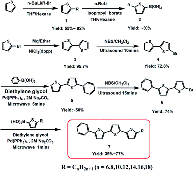
A series of phenylterthiophene-based monoalkyl liquid crystalline organic semiconductors, Ph-(Tp)3-Cn, were successfully synthesized according to Scheme 1. In the synthesis, alkyl thiophene boronic acid (2),8,9 which was obtained using thiophene as the starting material through two-step lithiation reactions, and Ph-BTP-Br (6) prepared from 2-bromothiophene were coupled by a microwave-assisted Suzuki-coupling (the details of the synthesis can be found in ESI†).10 All compounds were light yellow solids, and their chemical structures were confirmed by 1H-NMR spectra and high-resolution mass spectrometry (HRMS).Mesomorphic behaviours
The mesophase behaviours of Ph-(Tp)3-Cn were investigated by DSC, POM, and variable temperature power XRD. All compounds showed a single liquid crystal phase. The phase transition temperature and enthalpy data are summarized in Table 1.| Compound | Phase [T/°C (ΔH/J g−1)] phasea,b,c |
|---|---|
| a Cr: crystal; Cr1: crystal 1; Cr2: crystal 2; Sm: smectic; I: isotropic.b All data obtained from 2nd heating and 1st cooling (10 °C min−1), 1st row observed on 2nd heating and 2nd row observed on 1st cooling.c ∼ indicates that there are multiple small peaks inside. | |
| Ph-(Tp)3-C6 | Cr 66.0(−3.5) SmE 179.9(−68.9) I |
| Cr 67.9(4.3) SmE 176.8(69.4) I | |
| Ph-(Tp)3-C8 | Cr ∼ 72.5(−20.5) SmE 177.8(−56.3) I |
| Cr 56.8(19.6) SmE 172.7(56.3) I | |
| Ph-(Tp)3-C10 | Cr1 ∼ 77.0(−19.6) Cr2 ∼ 88.3(−2.1) SmE 173.9(−50.4) I |
| Cr1 64.8(35.5) SmE 170.4(50.4) I | |
| Ph-(Tp)3-C12 | Cr1 ∼ 84.3(21.6) Cr2 ∼ 98.4(−44.6) SmE 171.1(−51.0) I |
| Cr1 72.0(50.5) SmE 167.1(51.1) I | |
| Ph-(Tp)3-C14 | Cr1 ∼ 91.7(−5.3) Cr2 ∼ 104.2(−18.8) Cr3 ∼ 112.3(−21.6) SmE 167.7(−36.6) I |
| Cr1 81.6(46.2) SmE 163.9(36.9) I | |
| Ph-(Tp)3-C16 | Cr1 ∼ 101.5 Cr2 113.0(−69.2) SmE 165.0(−50.3) I |
| Cr1 88.1(71.2) SmE 161.4(50.1) I | |
| Ph-(Tp)3-C18 | Cr1 92.9(6.8) Cr2 116.5(−97.2) SmE 161.0(−43.2) I |
| Cr1 95.0(87.1) SmE 157.3(43.5) I | |
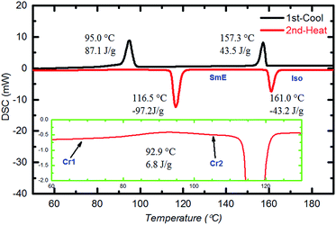
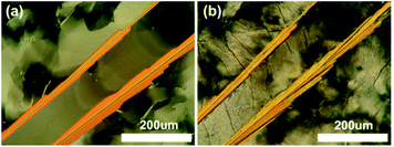
Fig. 2 shows the DSC curves of a typical compound, Ph-(Tp)3-C18 at a scan rate of 10 °C min−1. In the curves, two obvious endothermic phase transition peaks at 116.5 °C and 161.0 °C were observed during the second heating run. This indicates that Ph-(Tp)3-C18 exhibits a mesophase. In addition, in the mesophase, a typical mosaic texture is observed in a POM image at 130 °C (Fig. 3a), which often appears in the texture of highly ordered phases obtained from an isotropic phase without low-ordered liquid crystalline phases such as SmA and SmC phases,11 indicating a highly ordered smectic phase, e.g., SmE, SmH or SmK. Furthermore, the appearance of cracks in the POM texture at 30 °C (Fig. 3b) suggested that the low temperature phase was a crystal phase, which also distinguished the mesophase from the crystalline phase.12 Moreover, an additional small exothermic broad peak at 92.9 °C, as shown in the inset of Fig. 2, was observed during the second heating run. Because of the heating run of DSC, this exothermic peak is attributed to phase transition for more stable ordered crystal phase as compared to the crystal phase at room temperature.
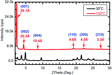
The mesophase was studied in detail by the variable temperature power XRD. Fig. 4 shows the typical XRD patterns of Ph-(Tp)3-C18 at 150 °C on heating (red line). In the small angle area (2θ = 2–5°), the d spacing of the first reflection (d = 39.1 Å) was almost equal to a molecular length of Ph-(Tp)3-18 calculated by MOPAC (dcal. = 39.7 Å). Moreover, in the wide-angle region (2θ = 15–30°), a set of three sharp peaks for d = 4.6 Å, 4.0 Å, and 3.5 Å was the signature of the SmE phase.7b,13 Thus, the mesophase was assigned to be the SmE phase. Furthermore, as temperature decreased, e.g., at 30 °C, multiple peaks appeared around the wide-angle region, which were attributed to the additional reflection in the crystal phase, which further supported the present identification (Fig. 4, black line).
According to DSC, POM, and XRD results, the phase transition behaviour of Ph-(Tp)3-C18 was determined to be crystal 1 (Cr1) → crystal 2 (Cr2) → smectic E (SmE) → isotropic (I) in the heating process.
Similarly, DSC, POM, and XRD results of other compounds were obtained, as shown in ESI Fig. S1–S3.† Their mesophase properties are summarized in Table 1.
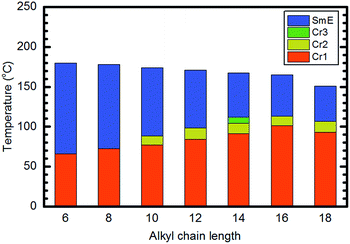
Fig. 5 shows a summary of phase transition behaviours of various Ph-(Tp)3-Cn as a function of temperature. As shown in Fig. 5, all compounds exhibited a highly ordered liquid crystal phase, i.e., SmE phase, and the mesophase ranges and isotropic points were decreased slightly as the alkyl side chain lengths increased. Furthermore, it should be noted that all the studied Ph-(Tp)3-Cn exhibited an additional crystal phase (Cr2) except for Ph-(Tp)3-C14, which exhibited another crystal phase (Cr3).
Effect of TA on the crystal structure in polycrystalline thin films
To investigate the effects of TA on the crystal structure of Ph-(Tp)3-Cn crystalline films derived from the SmE phase, the films were fabricated by spin coating their 0.75% p-xylene solution on glass substrates at an elevated temperature for each SmE phase. The morphology in the resulting films was very uniform and flat as expected from the previous results due to smectic liquid crystallinity.2f,4a,6c The crystal structure in the films before and after TA was studied by the variable temperature power XRD in the small angle region (2θ = 1–5°).Fig. 6 shows the XRD patterns of Ph-(Tp)3-C18 as a function of TA temperature in the crystal state. The black curve is the XRD pattern obtained before TA, i.e., as-coated film, and the other curves are the XRD patterns obtained after TA at different temperatures for 5 min.
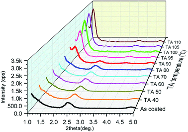 | ||
| Fig. 6 The thin film XRD pattern of Ph-(Tp)3-C18 obtained before and after TA at different temperatures in the crystal state (TA at each temperature for 5 min, then cooling to room temperature). | ||
The XRD peaks at around 2θ = 2.42° in Fig. 6 (in ESI Fig. S4†) were assigned to the d-spacing of a layer thickness of a monolayer consisting of Ph-(Tp)3-C18 molecules, which was determined to be 36.5 Å, i.e., for Cr1, indicating that crystals consisted of molecular layers of Ph-(Tp)3-C18, whose thickness was shorter than the molecular length of Ph-(Tp)3-C18 calculated by MOPAC, i.e., dcal. = 39.7 Å. The peak position and its intensity for these peaks remained almost unchanged until TA at 90 °C. A new peak at around 2θ = 1.23° in Fig. 6, a red curve as shown in ESI Fig. S4,† corresponding to the d spacing of ≈71.8 Å, appeared after TA at 90 °C. This d-spacing was almost double (≈1.97) that of the layer thickness in the crystals before TA; this indicated that the crystalline thin films were transformed into bilayered crystals, i.e., Cr2, after TA. The intensity of this new peak increased with an increase in the TA temperature and saturated after TA at 100 °C; this suggested that the bilayer crystal was more thermally stable than the monolayered crystal fabricated via the SmE phase.
Judging from the XRD patterns in ESI Fig. S5,† all the crystalline thin films of Ph-(Tp)3-Cn fabricated by spin-coating at a temperature of SmE phase yielded monolayered crystals when alkyl side chain lengths were n ≥ 10. Moreover, the films are transformed into bilayered crystals after TA at a temperature around their crystal temperature; this is in accordance with the previous results of Ph-BTBT-C10.2f
The present results can be summarized as follows: the as-spin coated crystalline films obtained from the SmE phase are monolayered (Cr1) and can be transformed into bilayered crystals (Cr2) after TA at around the crystallization temperatures when alkyl side chain length is longer than C10, as shown in Table 2.
| Compound | Ta (°C) | dobs. (Å) | dcal.b (Å) | Miller index (hkl) |
|---|---|---|---|---|
| a Data was obtained at TA at a certain temperature for 5 min.b The single molecular length calculated by MOPAC. | ||||
| Ph-(Tp)3-C6 | 30 | 24.1 | 24.9 | (001) |
| Ph-(Tp)3-C8 | 30 | 25.9 | 27.4 | (001) |
| Ph-(Tp)3-C10 | TA at 83 | 53.7 | 29.8 | (001) |
| 27.4 | (002) | |||
| Ph-(Tp)3-C12 | TA at 94 | 61.3 | 32.3 | (001) |
| 29.5 | (002) | |||
| Ph-(Tp)3-C14 | TA at 107 | 59.6 | 34.8 | (001) |
| 31.6 | (002) | |||
| Ph-(Tp)3-C16 | TA at 106 | 64.4 | 37.2 | (001) |
| 33.7 | (002) | |||
| Ph-(Tp)3-C18 | TA at 110 | 71.8 | 39.7 | (001) |
| 36.9 | (002) | |||
Although XRD results obtained from the films of Ph-(Tp)3-Cn before and after TA indicated the existence of a monolayered and bilayered lamellar molecular packing in the spin-coated crystalline thin films, in fact, it was hard to obtain the exact images of molecular packing in the resulting films by AFM and STM techniques because of the vulnerable nature of the present films and the difficulty in analysing the XRD data for the films polycrystallized.14 The exploration of the exact molecular packing of the films will be conducted in future.
Considering the unique asymmetrical molecular structures of monoalkyl Ph-(Tp)3-Cn which are similar with the biological membranes15 and ionic liquid crystals,16 a possible molecular packing is speculated, as shown in Fig. 7. According to recent studies on the SmE phase,17 the molecular alignment in the SmE phase is characterized by a microphase-separated structure of core moieties and side chains, as illustrated in Fig. 7, and closely packed herringbone molecular arrangement in a molecular plane. In the fabrication of the films by spin-coating a solution at the SmE temperature, the films are subjected to fast cooling from the SmE temperature to the crystallization temperature, i.e., the Cr1 state. Therefore, it is quite plausible that the monolayered structure and herringbone packing of molecules in the SmE film can be held in the resulting crystalline films (C1) without any destructive change of the molecular alignment, whereas alkyl side chains are frozen and tilted towards the substrate,17 i.e., layer plane, in which the Ph-(Tp)3 moieties sit perpendicular due to the same herringbone molecular alignment in the crystal.
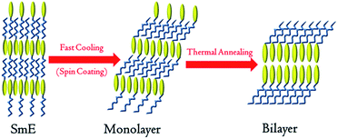 | ||
| Fig. 7 Schematic of a transition from the SmE phase to a monolayer structure and then a bilayer structure (yellow ellipse represents a rigid core and blue line represents the side alkyl chains). | ||
Subsequently, the resulting monolayered crystal (Cr1 state) is transformed into the bilayered crystal (Cr2 state) by successive TA.2f,16,18 Thus, film uniformity and morphology of the bilayered crystal can be inherited from the SmE film basically. This is quite beneficial for polycrystalline thin films with good surface morphology and area uniformity.
Effect of TA on the OFET performance
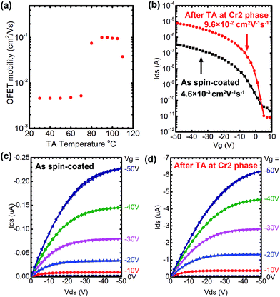
As discussed in the previous section, TA causes the crystal-to-crystal phase transition from the monolayered crystal (Cr1) to the bilayered crystal (Cr2),2f as is the case of Ph-BTBT-10, in which the resulting bilayered crystals have a head-to-head arrangement in a molecular layer and afford enhanced mobility in OFET devices.2f To examine the generality of this phenomenon, we fabricated bottom gate top contact OFET devices with polycrystalline thin films of all compounds after spin-coating their 0.75% p-xylene solution on SiO2/Si substrates in each SmE temperature and cooling the resulting films at room temperatures. Au electrodes of 50 nm thickness were deposited onto the resulting films through shadow masks. The OFET performance was investigated before and after TA.Fig. 8(a) shows the mobility of OFETs fabricated with Ph-(Tp)3-C18 as a function of TA temperatures in the crystal state, which has been estimated from transfer characteristics of the devices in the linear region at a room temperature after TA at a given temperature for 5 min. The FET mobility started to increase at around 80 °C, where the phase transition to Cr2 started, and then dropped at around 110 °C, which coincided with the phase transition behaviour of Ph-(Tp)3-C18 elucidated by DSC measurement at a slow scanning rate of 1 °C min−1 (ESI Fig. S6†) and XRD results shown in Fig. 6. The typical output and transfer characteristics of Ph-(Tp)3-C18 in the monolayered crystal (Cr1) and the bilayered crystal (Cr2), that is, before and after TA, are shown in Fig. 8(b)–(d). It is clear that the FET mobility of ∼4.6 × 10⁻³ cm2 V−1 s−1 for Cr1 is increased by more than one order of magnitude up to 0.1 cm2 V−1 s−1 in Cr2 after TA.
The OFETs fabricated with other Ph-(Tp)3-Cn followed this trend although the degree of enhancement of the mobility depended on alkyl chain lengths, as shown in Fig. 9: OFETs fabricated with the Cr1 crystal of Ph-(Tp)3-Cn showed the mobility of around 5 × 10⁻³ cm2 V−1 s−1 irrespective of alkyl chain lengths, Cn; after TA at the Cr2 phase for 5 min, the mobility was increased by a factor of 2–20. In the present study, the FET performance of these devices has not been optimized yet, but it is still available to find a general trend of the effect of TA on the device performance. In fact, as the alkyl side chain lengths increased (except for n = 10), the FET mobility after TA increased up to 0.1 cm2 V−1 s−1. Moreover, their OFET performance is summarized in detail in ESI Table S1 and Fig. S7.†
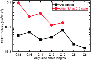 | ||
| Fig. 9 OFET mobility of Ph-(Tp)3-Cn before and after TA (TA) at Cr2 phase (all data was obtained from the transfer curves in liner area at Vds = −50 V). | ||
There are several possible factors, such as improvement of film crystallinity and electrical contact with electrode materials of Au and the enhanced transfer integrals among the molecules in the bilayered crystal, contributing to the enhancement of mobility after TA. However, judging from the FET mobility and the formation of the bilayered crystals as a function of TA temperature, as shown in Fig. 6 and 8(a), respectively, it is very clear that the formation of the bilayered crystal and the enhancement of FET mobility occur at around 80 °C abruptly, whereas they hardly occur at a temperature range lower than 80 °C. This trend basically followed the previously reported case of Ph-BTBT-10.
Therefore, we have concluded that the major contribution to the enhancement of FET mobility in OFETs fabricated with Ph-(Tp)3-C18 after TA is attributed to the crystal transition from Cr1 to Cr2 induced by thermal annealing, rather than improvement of film crystallinity and/or the electrical contact with Au electrodes, both of which may occur in thermal annealing at the same time. In fact, the exact reason why the bilayered crystal gives higher mobility is not clear although we can deduce that Cr1 is less ordered as compared to Cr2 because Cr1 inherits the disordered nature of the SmE phase, and the bilayered crystal has two conduction channels in the vicinity of the gate insulator, whose trap states are easily filled to reduce the harmful effect on the source–drain current.
Recently, vacuum evaporated polycrystalline films of asymmetric BTBT derivatives, such as BTBT-Tp-Cn19 and BTBT-Ph-12,20 and solution-grown single crystals of BTT-Tp-12![[thin space (1/6-em)]](https://www.rsc.org/images/entities/char_2009.gif) 21 were applied to fabricate processed OFETs. Judging from our previous and present results on the monoalkyl smectic liquid crystals, these materials would also be available for solution-processed bilayered crystalline thin films if their liquid crystallinity is utilized to fabricate a film.
21 were applied to fabricate processed OFETs. Judging from our previous and present results on the monoalkyl smectic liquid crystals, these materials would also be available for solution-processed bilayered crystalline thin films if their liquid crystallinity is utilized to fabricate a film.
The results obtained from Ph-BTBT-10 and Ph-(Tp)3-Cn lead to a possible conclusion that a monolayered crystal can be easily formed with a SmE film of mono-alkylated smectic liquid crystals, irrespective of the core structure, e.g., Ph-BTBT and Ph-(Tp)3, transformed into the bilayered crystals with the aid of thermal annealing, and the resulting bilayered crystals exhibit enhanced mobility in OFETs, if applied. Therefore, this crystal-to-crystal phase transition accompanied by enhancement of FET mobility observed in Ph-BTBT-10 is not a particular case of Ph-BTBT-10, having an extended aromatic fused ring system, but probably common in the monoalkyl smectic liquid crystals with an extended π-conjugate core and an alkyl chain long enough to stabilize the microphase-separated structure of core and side chain moieties. In addition, it is worth noticing that the formation of the bilayered crystals via the SmE phase allows us to prepare a uniform and flat thin film of bilayered crystals suitable for OFET applications by solution processes.
From a molecular design point of view, the present findings suggest a new possible strategy of molecular design for high quality OFET materials even when a π-conjugate moiety for charge carrier transport is kept unchanged: mono-alkylated OFET materials provide us with feasibility of fabricating bilayered polycrystalline films, leading to enhanced mobility in OFETs; for example, C8-BTBT, i.e., 2,7-dioctyl-BTBT, cannot form the bilayered crystal because of its symmetric chemical structure, but Ph-BTBT derivatives afford the bilayered crystal with higher mobility as reported. Furthermore, this type of materials has another benefit of higher solubility in solvents, for example, compared with the dimer type of OFET materials with the same core size, dialkyl dimer type of OFET materials, such as Cn-(Tp)3-phenylene–phenylene-(Tp)3-Cn, hardly dissolve in organic solvents, whereas monoalkyl OFET materials with the monomer core structure, e.g., Ph-(Tp)3-Cn, show good solubility although they can give a quasi-dimer type of core structure of ((Tp)3-Ph–Ph-(Tp)3) in the bilayered crystal.
Conclusions
A series of asymmetric monoalkyl smectic liquid crystals, Ph-(Tp)3-Cn, was synthesized and the formation of monolayered crystals and the effect of thermal annealing on their transformation to the bilayered crystals and OFET performance fabricated with these polycrystalline films were investigated. It was found that the monolayered crystals of Ph-(Tp)3-Cn were easily formed by spin-coating its solution at a SmE temperature, the crystal-to-crystal transition from monolayered to bilayered crystals was induced thermally when the alkyl side chain length n ≥ 10, and OFET mobility in FETs fabricated with the polycrystalline thin films was dramatically enhanced up to one order of magnitude when the bilayered crystals were formed.The present result indicates that this thermally-induced crystal-to-crystal phase transition and simultaneous enhancement of FET mobility in OFETs fabricated with the monolayered crystals is not specific in a particular material of Ph-BTBT derivatives, but is common in monoalkyl smectic liquid crystals with an extended π-conjugate moiety; this indicates the availability of a new strategy of molecular design featuring the bilayered crystals fabricated with monoalkyl smectic liquid crystals for boosting mobility in soluble OFETs materials.
Experimental
General
All commercially available reagents and solvents were used as received from Aldrich Chemical, Tokyo Chemical Industry, Wako Pure Chemical Industries and Kanto Chemical Co., Inc. unless otherwise noted.1H-NMR spectra were obtained using Bruker NMR spectrometers (DMX 400 MHz), and chemical shifts are given in parts per million (δ) and referenced from tetramethylsilane (TMS). Multiplicities of the peaks are given as s = singlet, d = doublet, t = triplet, and m = multiplet. High resolution mass spectrum (HRMS) was obtained using a double-focusing magnetic sector mass spectrometer, JEOL JMS-700.
Microwave-assisted reactions were carried out in a Milestone START S microwave synthesis system. Differential scanning calorimetry (DSC) was carried out using the Shimadzu instruments' DSC-60. Polarizing optical microscopy was carried out using a Nikon OPTIPHOT2-POL microscope equipped with a Mettler Toledo FP82HT hot stage. 1D WXRD studies were conducted using a Rigaku RAD-2X diffractometer with CuKα radiation.
Bulk film samples for XRD measurements were prepared by melting the powder of the sample from Iso to room temperature on a glass slide substrate with a polyimide cover film before measurement, and the polyimide cover films were removed and thin film samples were prepared by spin coating at 3000 rpm for 30 s at a SmE temperature, which was similar with OFET thin film fabrication except for the use of glass slide as substrates.
Device fabrication and characterization
Top contact bottom gate OFET devices were fabricated using SiO2 (300 nm)/p+-Si substrates. Polycrystalline thin films of all compounds were fabricated by spin coating at 3000 rpm for 30 s at a SmE temperature, for which the solution was preheated. The solution concentration was 0.75 wt% p-xylene. The detail of spin coating procedure can be found in our previously reported studies.2f,4a After spin coating, 50 nm thick Au electrodes were deposited on the thin films under 2 × 10⁻⁶ Torr through shadow masks. The channel length (L)/width (W) was 100/500 μm.The OFET performance was characterized by two source measurement units (8252, ADCMT) under ambient conditions at room temperature. The mobility (μ) was calculated by plotting the square root of the source–drain current (Ids) versus gate voltage (Vg) in the linear region using the equation Ids = Ci(W/L)μ(Vg − Vth)Vds, where Ci is capacitance of gate insulator and Vth is threshold voltage obtained from the linear region (Vds = −50 V).
Synthesis
2,2′-Bithiophene (2) was synthesized by Kumada coupling started with 2-bromothiophene in 95.7% yield.10a 5-Bromo-2,2′-bithiophene (4) was synthesized by a convenient ultrasound reaction using NBS as a bromination source in 72.8% yield.10d 5′-Phenyl-2,2′-bithiophene (5) was prepared by a microwave-assisted Suzuki coupling between 5-bromo-2,2′-bithiophene (4) and phenylboronic acid in ∼50% yield.10c In addition, the synthesis procedure of 5-bromo-2,2′-bithiophene (4) and 5′-phenyl-2,2′-bithiophene (5) was similar to that of 5-bromo-5′-phenyl-2,2′-bithiophene (6) reported in ESI† and Ph-(Tp)3-Cn, respectively.General synthesis of Ph-(Tp)3-Cn (6 ≤ n ≤ 18)
To a stirred solution of 5-bromo-5′-phenyl-2,2′-bithiophene 0.32 g (1 mmol), 5-alkyl-2-thiopheneboronic acid (1.2 mmol), 2 M Na2CO3 0.5 ml (1 mmol) in 7.5 ml diethylene glycol, Pd(PPh3)4 11.5 mg (1 mol%) was added. After being degassed with argon for 3 times, the solution was irradiated using a microwave reactor for 1 min under 1200 W at 190 °C. As the solution cooled down to room temperature, 100 ml water was added. After being vigorously stirred for 5 min, the mixture was filtered. The filter cake was obtained and purified by column chromatography on silica gel (cyclohexane/toluene: 1/20) and then recrystallized from toluene to obtain a pure light yellow solid.Conflicts of interest
There are no conflicts to declare.Acknowledgements
We thank Ms Yukiko Takayashiki, Dr Takayuki Usui and Dr Hisashi Okamura for very useful advice in synthesis and Dr Akira Ohno and Dr Yifei Wang for very useful advice in calculations and measurements. This work was partly supported by KAKENHI, grant numbers 15K05662.Notes and references
- (a) M. Berggren, D. Nilsson and N. D. Robinson, Nat. Mater., 2007, 6, 3–5 CrossRef CAS PubMed; (b) B. Kang, W. H. Lee and K. Cho, ACS Appl. Mater. Interfaces, 2013, 5, 2302–2315 CrossRef CAS PubMed; (c) H. Sirringhaus, Adv. Mater., 2014, 26, 1319–1335 CrossRef CAS PubMed.
- (a) H. Ebata, T. Izawa, E. Miyazaki, K. Takimiya, M. Ikeda, H. Kuwabara and T. Yui, J. Am. Chem. Soc., 2007, 129, 15732–15733 CrossRef CAS PubMed; (b) T. Yamamoto and K. Takimiya, J. Am. Chem. Soc., 2007, 129, 2224 CrossRef CAS PubMed; (c) C. Wang, H. Dong, W. Hu, Y. Liu and D. Zhu, Chem. Rev., 2012, 112, 2208–2267 CrossRef CAS PubMed; (d) T. Okamoto, C. Mitsui, M. Yamagishi, K. Nakahara, J. Soeda, Y. Hirose, K. Miwa, H. Sato, A. Yamano, T. Matsushita, T. Uemura and J. Takeya, Adv. Mater., 2013, 25, 6392–6397 CrossRef CAS PubMed; (e) J. Mei, Y. Diao, A. L. Appleton, L. Fang and Z. Bao, J. Am. Chem. Soc., 2013, 135, 6724–6746 CrossRef CAS PubMed; (f) H. Iino, T. Usui and J. Hanna, Nat. Commun., 2015, 6, 6828 CrossRef CAS PubMed.
- (a) H. R. Tseng, H. Phan, C. Luo, M. Wang, L. A. Perez, S. N. Patel, L. Ying, E. J. Kramer, T. Q. Nguyen, G. C. Bazan and A. J. Heeger, Adv. Mater., 2014, 26, 2993–2998 CrossRef CAS PubMed; (b) S. Holliday, J. E. Donaghey and I. McCulloch, Chem. Mater., 2014, 26, 647–663 CrossRef CAS; (c) J. Park, J. W. Chung, J.-Y. Kim, J. Lee, J. Y. Jung, B. Koo, B.-L. Lee, S. W. Lee, Y. W. Jin and S. Y. Lee, J. Am. Chem. Soc., 2015, 137, 12175–12178 CrossRef CAS PubMed; (d) Z. Zhao, Z. Yin, H. Chen, L. Zheng, C. Zhu, L. Zhang, S. Tan, H. Wang, Y. Guo, Q. Tang and Y. Liu, Adv. Mater., 2017, 29, 1602410 CrossRef PubMed; (e) Y. Gao, Y. Deng, H. Tian, J. Zhang, D. Yan, Y. Geng and F. Wang, Adv. Mater., 2017, 29, 1606217 CrossRef PubMed; (f) J. Yang, Z. Zhao, H. Geng, C. Cheng, J. Chen, Y. Sun, L. Shi, Y. Yi, Z. Shuai, Y. Guo, S. Wang and Y. Liu, Adv. Mater., 2017, 29, 1702115 CrossRef PubMed; (g) E. Lee, M. Y. Lee, A. Choi, J. Kim, O. Y. Kweon, J. Kim, J. Y. Jung, T. Shin, J. H. Oh, J. Park and S. Y. Lee, Adv. Electron. Mater., 2017, 3, 1700142 CrossRef.
- (a) H. Iino and J. Hanna, Adv. Mater., 2011, 23, 1748–1751 CrossRef CAS PubMed; (b) H. Iino and J. Hanna, Polym. J., 2017, 49, 23–30 CrossRef CAS.
- (a) F. Garnier, R. Hajlaoui, A. El Kassmi, G. Horowitz, L. Laigre, W. Porzio, M. Armanini and F. Provasoli, Chem. Mater., 1998, 10, 3334–3339 CrossRef CAS; (b) H. E. Katz, J. G. Laquindanum and A. J. Lovinger, Chem. Mater., 1998, 10, 633–638 CrossRef CAS; (c) A. van Breemen, P. T. Herwig, C. H. T. Chlon, J. Sweelssen, H. F. M. Schoo, S. Setayesh, W. M. Hardeman, C. A. Martin, D. M. de Leeuw, J. J. P. Valeton, C. W. M. Bastiaansen, D. J. Broer, A. R. Popa-Merticaru and S. C. J. Meskers, J. Am. Chem. Soc., 2006, 128, 2336–2345 CrossRef CAS PubMed; (d) S. Tatemichi, M. Ichikawa, T. Koyama and Y. Taniguchi, Appl. Phys. Lett., 2006, 89, 112108 CrossRef; (e) J. C. Maunoury, J. R. Howse and M. L. Turner, Adv. Mater., 2007, 6, 805–809 CrossRef; (f) K. Oikawa, H. Monobe, K. Nakayama, T. Kimoto, K. Tsuchiya, B. Heinrich, D. Guillon, Y. Shimizu and M. Yokoyama, Adv. Mater., 2007, 19, 1864–1868 CrossRef CAS; (g) Y. Kunugi, Y. Busujima, M. Ikari, K. Okamoto and K. Ogino, ECS Trans., 2008, 16, 273–282 CrossRef CAS.
- (a) H. Iino and J. Hanna, Jpn. J. Appl. Phys., 2006, 45, L867–L870 CrossRef CAS; (b) H. Iino and J. Hanna, Mol. Cryst. Liq. Cryst., 2009, 510, 259–267 CAS; (c) H. Iino and J. Hanna, J. Appl. Phys., 2011, 109, 074505 CrossRef; (d) H. Iino and J. Hanna, Mol. Cryst. Liq. Cryst., 2011, 542, 237–243 CAS.
- (a) H. Iino, T. Kobori and J. Hanna, Jpn. J. Appl. Phys., 2012, 51, 11PD02 CrossRef; (b) H. Iino, T. Kobori and J. I. Hanna, J. Non-Cryst. Solids, 2012, 358, 2516–2519 CrossRef CAS.
- (a) P. Bäuerle, F. Würthner, G. Götz and F. Effenberger, Synthesis, 1993, 11, 1099–1103 CrossRef; (b) S. Ponomarenko and S. Kirchmeyer, J. Mater. Chem., 2003, 13, 197–202 RSC; (c) S. Pu, C. Zhu, Y. Rao, G. Liu and H. Wei, J. Mol. Struct., 2009, 921, 89–100 CrossRef CAS.
- (a) A. N. Cammidge, V. H. M. Goddard, H. Gopee, N. L. Harrison, D. L. Hughes, C. J. Schubert, B. M. Sutton, G. L. Watts and A. J. Whitehead, Org. Lett., 2006, 8, 4071–4074 CrossRef CAS PubMed; (b) J. Wang, H. Xu, B. Li, X. P. Cao and H. L. Zhang, Tetrahedron, 2012, 68, 1192–1197 CrossRef CAS.
- (a) C. van Pham, A. Burkhardt, R. Shabana, D. D. Cunningham, H. B. Mark and H. Zimmer, Phosphorus, Sulfur Silicon Relat. Elem., 1989, 46, 153–168 Search PubMed; (b) M. Melucci, G. Barbarella and G. Sotgiu, J. Org. Chem., 2002, 67, 8877–8884 CrossRef CAS PubMed; (c) S. Hotta and T. Katagiri, J. Heterocycl. Chem., 2003, 40, 845–850 CrossRef CAS; (d) P. Arsenyan, E. Paegle and S. Belyakov, Tetrahedron Lett., 2010, 51, 205–208 CrossRef CAS.
- I. Dierking, Textures of Liquid Crystals, Wiley-VCH, Weinheim, 2003, pp. 141–144 Search PubMed.
- S. K. Prasad, D. S. S. Rao, S. Chandrasekhar and S. Kumar, Mol. Cryst. Liq. Cryst., 2003, 396, 121–139 CrossRef CAS.
- Handbook of Liquid Crystals: Fundamentals, ed. D. Demus, J. W. Goodby, G. W. Gray, H.-W. Spiess and V. Vill, Wiley-VCH, Weinheim, 1998, ch. 3, vol. 1, pp. 661–668 Search PubMed.
- (a) M. H. Hara, Y. Iwakabe, K. Tochigi, H. Sasabe, A. F. Garito and A. Yamada, Nature, 1990, 344, 228–230 CrossRef CAS; (b) D. P. E. Smith, J. K. H. Hörber, G. Binning and H. Nejoh, Nature, 1990, 344, 641–644 CrossRef CAS; (c) Y. Iwakabe, M. Hara, K. Kondo, K. Tochigi, A. Mukoh, A. Yamada, A. F. Garito and H. Sasabe, Jpn. J. Appl. Phys., 1991, 30, 2542–2546 CrossRef CAS; (d) J. Y. Fang, Z. H. Lu, G. W. Ming, Z. M. Ai, Y. Wei and P. Stroeve, Phys. Rev. A, 1992, 46, 4963 CrossRef CAS PubMed; (e) F. Tao and S. L. Bernasek, Surf. Sci., 2007, 601, 2284–2290 CrossRef CAS; (f) C. Fu, H.-P. Lin, J. M. Macleod, A. Krayev, F. Rosei and D. F. Perepichka, Chem. Mater., 2016, 28, 951–961 CrossRef CAS.
- (a) M. Bretscher, Nat. New Biol., 1972, 236, 11–12 CrossRef CAS PubMed; (b) J. F. Nagle and S. Tristram-Nagle, Biochim. Biophys. Acta, 2000, 1469, 159–195 CrossRef CAS PubMed; (c) R. P. Richter, R. Berat and A. R. Brisson, Langmuir, 2006, 22, 3497–3505 CrossRef CAS PubMed.
- L. Li, J. Groenewold and S. J. Picken, Chem. Mater., 2005, 17, 251–257 Search PubMed.
- (a) Y. Yamamura, T. Adachi, T. Miyazawa, K. Horiuchi, M. Sumita, M. Massalska-Arodź, S. Urban and K. Saito, J. Phys. Chem. B, 2012, 116, 9255–9260 CrossRef CAS PubMed; (b) K. Saito, T. Miyazawa, A. Fujiwara, M. Hishida, H. Saitoh, M. Massalska-Arodź and Y. Yamamura, J. Chem. Phys., 2013, 139, 114902 CrossRef PubMed; (c) T. Miyazawa, Y. Yamamura, M. Hishida, S. Nagatomo, M. Massalska-Arodź and K. Saito, J. Phys. Chem. B, 2013, 117, 8293–8299 CrossRef CAS PubMed.
- (a) C. Grigoriadis, C. Niebel, C. Ruzié, Y. H. Geerts and G. Floudas, J. Phys. Chem. B, 2014, 118, 1443–1451 CrossRef CAS PubMed; (b) G. Gbabode, M. Dohr, C. Niebel, J.-Y. Balandier, C. Ruzié, P. Négrier, D. Mondieig, Y. H. Geerts, R. Resel and M. Sferrazza, ACS Appl. Mater. Interfaces, 2014, 6, 13413–13421 CrossRef CAS PubMed; (c) S. Inoue, H. Minemawari, J. Tsutsumi, M. Chikamatsu, T. Yamada, S. Horiuchi, M. Tanaka, R. Kumai, M. Yoneya and T. Hasegawa, Chem. Mater., 2015, 27, 3809–3812 CrossRef CAS; (d) H. Minemawari, M. Tanaka, S. Tsuzuki, S. Inoue, T. Yamada, R. Kumai, Y. Shimoi and T. Hasegawa, Chem. Mater., 2017, 29, 1245–1254 CrossRef CAS.
- K. He, W. Li, H. Tian, J. Zhang, D. Yan, Y. Geng and F. Wang, ACS Appl. Mater. Interfaces, 2017, 9, 35427–35436 CAS.
- Y. He, M. Sezen, D. Zhang, A. Li, L. Yan, H. Yu, C. He, O. Goto, Y.-L. Loo and H. Meng, Adv. Electron. Mater., 2016, 2, 1600179 CrossRef.
- H. Tian, Y. Han, C. Bao, D. Yan, Y. Geng and F. Wang, Chem. Commun., 2012, 48, 3557–3559 RSC.
Footnote |
| † Electronic supplementary information (ESI) available: Synthesis procedure, DSC, POM, XRD and OFETs measurements. See DOI: 10.1039/c7ra11727b |
| This journal is © The Royal Society of Chemistry 2017 |


