
 Open Access Article
 This Open Access Article is licensed under a Creative Commons Attribution-Non Commercial 3.0 Unported Licence
Facile synthesis of nitrogen-doped porous carbon for high-performance supercapacitors
Wang Yangab,
Wu Yanga,
Lina Konga,
Ailing Songa and
Xiujuan Qin*ab
aHebei Key Laboratory of Applied Chemistry, College of Environmental and Chemical Engineering, Yanshan University, Qinhuangdao 066004, China
bState Key Laboratory of Metastable Materials Science and Technology, Yanshan University, Qinhuangdao 066004, China. E-mail: qinxj@ysu.edu.cn; Fax: +86-335-8059878; Tel: +86-335-8061569
First published on 5th December 2017
Abstract
Nitrogen-doped porous carbon (NCs) have been synthesized by direct pyrolysis of a mixture containing melamine, iron nitrate and ethylene diamine tetraacetic acid (EDTA). Both the addition of melamine and the carbonization temperature play critical roles in the formation of the unique structure. The results demonstrate that NC-700 shows the best electrochemical performance compared to the other samples. High specific capacitance (275 F g−1 at 0.3 A g−1) is obtained in 6 M KOH, and the capacitance still maintains 202 F g−1 when tested at 10 A g−1 (ca. 73.5% capacitance retention). Moreover, the NC-700 also possesses good cycling stability with only a loss of 2.0% after 10![[thin space (1/6-em)]](https://www.rsc.org/images/entities/char_2009.gif) 000 cycles at 10 A g−1. The facile preparation method and good electrochemical performance render NCs a promising candidate for supercapacitor applications.
000 cycles at 10 A g−1. The facile preparation method and good electrochemical performance render NCs a promising candidate for supercapacitor applications.
1. Introduction
Supercapacitors, including electrochemical double layer capacitors (EDLCs) and pseudocapacitors, have attracted widespread attention due to their higher power density than batteries and higher energy density than conventional dielectric capacitors.1–5 It is well known that carbon materials are the most common electrode materials for EDLCs ascribed to their high specific surface area and good electrical conductivity. Various carbon materials, such as activated carbon (AC), mesoporous carbon and graphene have been extensively reported as electrode materials for EDLCs.6–12 Nevertheless, the low specific capacitance of AC greatly limits its further application, and the preparation of other carbon materials constantly involves complicated and expensive synthesis routes, which has seriously restricted their practical applications. Therefore, facile and economical methods should be explored to prepare novel carbon materials.Recently, heteroatom doping is an effective approach to improve the capacitive performance of carbon materials for supercapacitors. To date, heteroatoms such as boron, nitrogen, oxygen, sulfur and phosphorus have been incorporated into porous carbon materials.13–17 The incorporation of heteroatoms, such as nitrogen, into carbon materials can affect the electron-donor characteristics of carbon materials, thus improving the capacitive behavior of supercapacitors. Moreover, the nitrogen-containing functional groups can also improve the wettability of carbon materials to electrolyte solution.18–20 Nitrogen-doped porous carbon is commonly prepared by treating porous carbon with ammonia, amines, or urea, or employing various nitrogen-containing synthetic polymers, biomass or biomass derivatives, and so on.21–24 However, the preparation of these existing nitrogen-doped carbon materials generally requires complex and time-consuming synthesis routes. Consequently, it is highly desirable to develop a facile strategy to effectively prepare heteroatom-doped carbon materials, which is crucial for widespread implementation.
Herein, we designed and synthesized nitrogen-doped porous carbon (NCs) through a simple method. Melamine was introducted into the chelate of EDTA and iron nitrate in the synthesis process, and the interaction between these three components at high temperature yielded the nitrogen species introduced into the carbon matrix. Quite intriguingly, the addition of melamine and the carbonization temperature can influence the formation of the unique structure. The prepared NC-700 present favorable pore structure, which is beneficial to rapid ion transport and effective ion adsorption. Furthermore, the effective heteroatom doping synergistically improve the physicochemical properties and the capacitive behavior. As a result, the NC-700 exhibits good electrochemical performance when employed as electrode material for supercapacitor.
2. Experimental
2.1. Chemicals
In this experiment, all chemicals were used as purchased without any further processing. Deionized water was employed throughout the experiment.2.2. Preparation of nitrogen-doped porous carbon
The nitrogen-doped porous carbon (NCs) were prepared via a preliminary heating process followed by carbonization at high temperature. Typically, 1.86 g EDTA, 2.02 g iron nitrate and 0.63 g melamine were dispersed in 25 mL deionized water, respectively. Subsequently, the EDTA solution and melamine solution were added into the iron nitrate solution with vigorous stirring at 90 °C to form homogeneous gel. Then the gel was put into oven for 12 hours to obtain the precursor. Afterwards, the precursor was annealed in tube furnace under inert atmosphere at desired temperature (700–900 °C) for 2 h with a heating rate of 5 °C min−1. The obtained products were then washed with 15 wt% HCl solution. Finally, the samples were filtered, washed with abundant distilled water, and dried at 80 °C overnight. The nitrogen-doped carbon samples were labeled as NC-x, where the x refers to the carbonization temperature. Comparatively, the carbon sample without melamine was also prepared at 700 °C and was named as C-700.2.3. Material characterization
The structure of as-prepared materials were measured by X-ray diffraction (XRD) on a Rigaku Smart Lab X-ray diffractometer operated at 40 kV with Cu Kα radiation at a scan rate of 5° min−1. The morphologies of all the samples were analyzed by high-resolution transmission electron microscopy (HRTEM, JEOL-2100F). Nitrogen adsorption and desorption isotherms were characterized by Micromeritics V-Sorb 2800P analyzer at 77 K. Pore size distribution was obtained by the Barrette–Joyner–Halenda (BJH) method. Elemental analysis was analyzed by X-ray photoelectron spectroscopy (XPS) with a Kratos XSAM-800 spectrometer with monochromatized Al Kα radiation.2.4. Electrochemical measurement
The electrochemical performance was tested in 6 M KOH electrolyte. Hg/HgO electrode and active carbon electrode were used as the reference electrode and the counter electrode, respectively. To prepare the working electrode, NCs, acetylene black and PTFE were mixed at a weight ratio of 80:15:5 to form the homogeneous slurry. Then, the slurry was continuously spread on current collectors of 1 cm2 nickel foam, and dried at 80 °C for 12 h. The total mass loading of each electrode was approximately 2 mg. The fabricated electrodes were pressed at 4 MPa for 30 s, and immersed in 6 M KOH electrolyte for 24 h. The specific capacitance of the working electrodes in three-electrode system was obtained from the galvanostatic discharge process via C = IΔt/(mΔV), where C is the specific capacitance (F g−1), I (A) refers the discharge current, Δt (s) is the discharge time, m (g) is the mass of the active material for working electrode and ΔV (V) is the potential change excluding the IR drop during the discharge process.
The galvanostatic charge–discharge measurement was recorded on a NEWARE auto-cycler. The potential window was −1.0 to 0.2 V in 6 M KOH for the three-electrode system. Cyclic voltammetry (CV) and electrochemical impedance spectroscopy (EIS) measurements were conducted on a CHI660E electrochemical workstation (Chenhua, Shanghai, China). The frequency range for the EIS measurement was from 1 mHz to 1 MHz with a perturbation amplitude of 5 mV.
3. Results and discussion
The general strategy for fabricating NC-700 is illustrated in Scheme 1. The nitrogen-doped porous carbon material was prepared by a novel method using nitrogen-containing carbon source. In a typical synthesis, the EDTA and iron ions were chelated under certain conditions, then the sol was formed after the evaporation of the solvent. In this process, the melamine was retained by the viscosity of the sol. After drying in oven, the precursor was carbonized at high temperature under inert atmosphere. Finally, the nitrogen porous carbon material was successfully prepared. In this strategy, iron can not only affect pore structure, but also can accelerate the catalytic graphitization of carbon materials. Simultaneously, the nitrogen atoms in EDTA and melamine can introduced into carbon rings in the carbonization process. Not surprisingly, the interaction between EDTA, iron and melamine results in the formation of the unique morphology.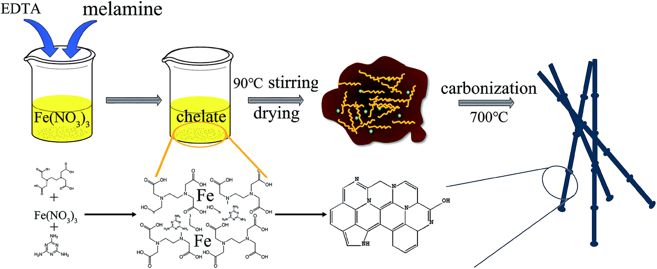 | ||
| Scheme 1 Schematic representation of the fabrication process of NC-700. | ||
Fig. 1(a–d) depicts the TEM images of the samples. Fig. 1(a) shows the TEM image of C-700, and it can be seen that the sample shows a matrix-type porous mesh structure without the addition of melamine. Clearly, the morphology of the NC-700 changes significantly after adding melamine in the preparation process (Fig. 1(b)). This may be attributed that the addition of melamine can prevent the re-polymerization of oligomeric molecules and impede the formation of three-dimensional network structure. Furthermore, the morphology of the material also changes along with the temperature varies from 700 °C to 900 °C, as shown in Fig. 1(c and d). The above results exhibit that the unique structure becomes smoother and shorter as the carbonization temperature rises.
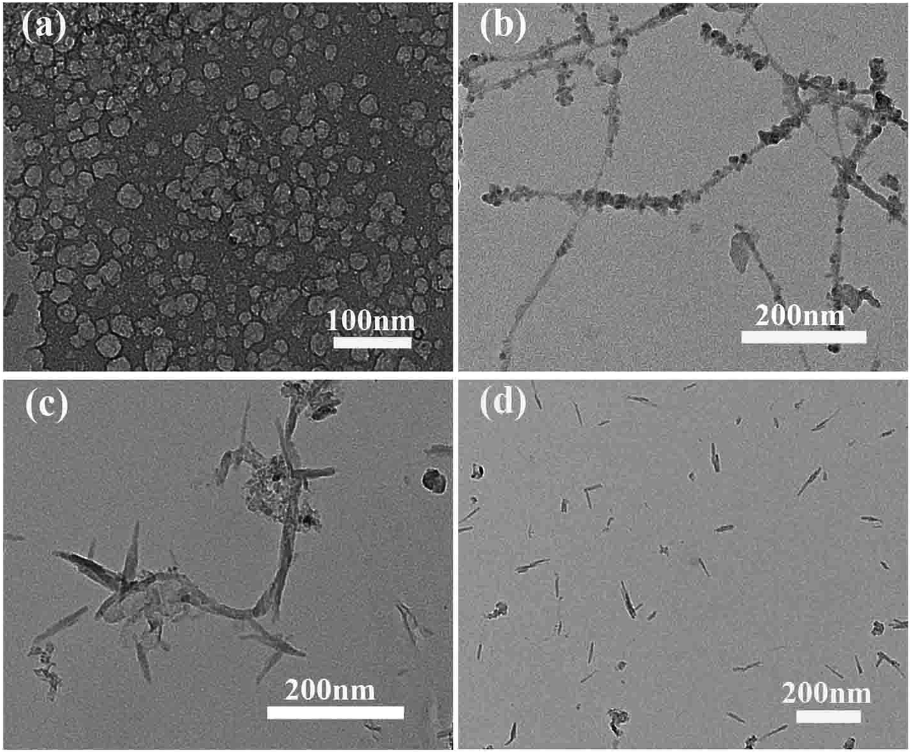 | ||
| Fig. 1 (a–d) TEM image of the samples; (a) C-700; (b) NC-700; (c) NC-800; (d) NC-900. | ||
XRD patterns of the carbon samples are shown in Fig. 2(a). It can be seen that the sample without melamine (C-700) has a narrow peak near 26° representing the (002) plane,25,26 which demonstrates a good graphitized structure. After adding melamine, the samples NC-x have a large broad peak near 25°, indicating that melamine is not conducive to the graphitization of materials. The possible reason is ascribed that the chelating effect between EDTA and iron was reduced after adding of melamine, that is, smaller ratio of chelate containing iron was formed. Therefore, the catalytic graphitization in carbonation process is low. Moreover, it is obvious that the (002) peak becomes broader and weaker as the carbonization temperature increases, demonstrating that the graphitization degree of the material decreases. As a result, high temperature is also not beneficial for chelating effect between EDTA and iron.
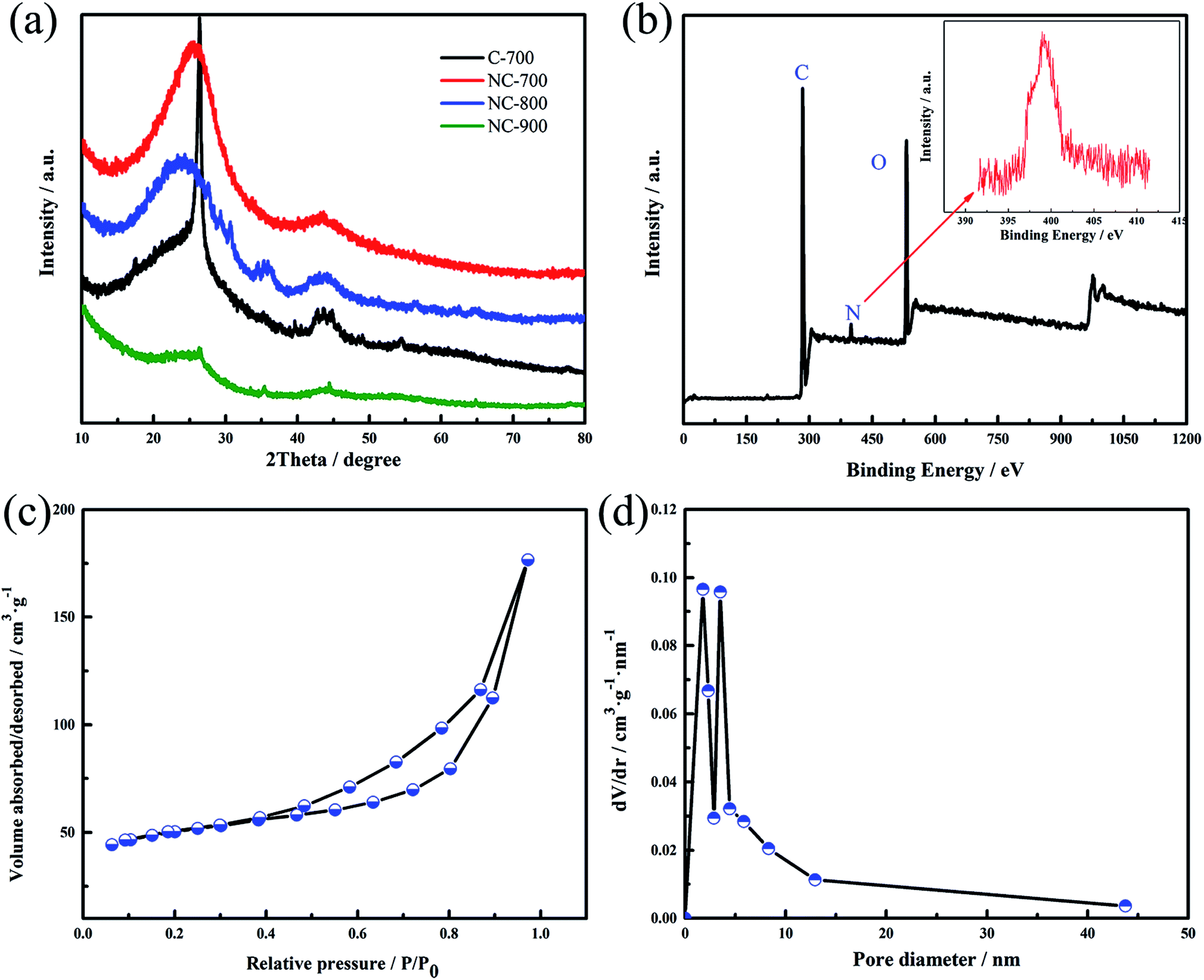 | ||
| Fig. 2 (a) XRD patterns of the samples; (b) XPS survey spectrum of NC-700; (c) nitrogen adsorption–desorption isotherm of NC-700; (d) pore size distribution of the NC-700. | ||
Chemical composition of the carbon sample NC-700 was analysed in detail by X-ray photoelectron spectroscopy (XPS) in Fig. 2(b). The survey spectrum of the sample shows a predominant C 1s peak at 284.5 eV, O 1s peak at 532 eV and N 1s peak at 399 eV.29,30 The atomic percent of C, O and N are 80%, 15.6% and 4.4%, respectively. The possible advantages of the nitrogen doping are as following: (i) the N and O doping produced the heteroatom functional groups on the carbon surface, which is favorable for electrolyte soaking into the interior of material; (ii) some functional groups have a considerable effect on the electrochemical performance and can provide additional pseudocapacitance; (iii) the doping of nitrogen heteroatoms can improve the electrical conductivity of the material and reduce the internal impedance of the material.31,32 In short, the carbon material modified by nitrogen heteroatom can greatly improve the electrochemical properties of carbon electrode materials.
Fig. 2(c and d) presents N2 adsorption–desorption isotherm and the pore size distribution of the NC-700. According to IUPAC classification,27 the isotherm belongs to type IV corresponding to porous carbon with meso-pore size distribution. When the relative pressure is greater than 0.4, there is a significant hysteresis loop, which indicates that the material has a mesoporous structure. When the relative pressure is greater than 0.9, the curve shows a sudden increase trend, indicating that there is a gap between the particles of the material. The specific surface area of the material is 308.5 m2 g−1 and the pore volume is 0.59 cm3 g−1. Fig. 2(d) shows that the NC-700 has a hierarchical pore structure with micropores of less than 2 nm and mesopores with pore diameters of about 3.5 nm. It is proved that micropores with less than 2 nm can provide a large area of adsorption sites for the accumulation of charge, which can facilitate the formation of electric double layer capacitance and improve the capacitance of electrode materials. The mesoporous about 3–4 nm provide an favorable path for the electrolyte ion diffusion, allowing the electrolyte ions to be transported quickly during the charge–discharge process at large current densities.28
To probe the electrochemical performance of the carbon samples, cyclic voltammetry (CV) and galvanostatic charge–discharge (GCD) were measured by three-electrode system in 6 M KOH. Fig. 3(a) presents the CV curves of the samples at the scan rate of 20 mV s−1. Clearly, the NCs shows a slightly distorted rectangular CV curve with a wide reversible hump, suggesting its electric double-layer capacitor (EDLC) performance along with the pseudocapacitance characteristics.33 The C-700 exhibits better-symmetric and rectangular CV curves, which can be ascribed to the absence of nitrogen doping. The GCD curves of the samples at 1.5 A g−1 (Fig. 3(b)) demonstrate that the NCs shows more non-linear characteristics than the C-700, further revealing the pseudo-capacitive feature generated from the doping elements,34 which is consistent with the CV result.
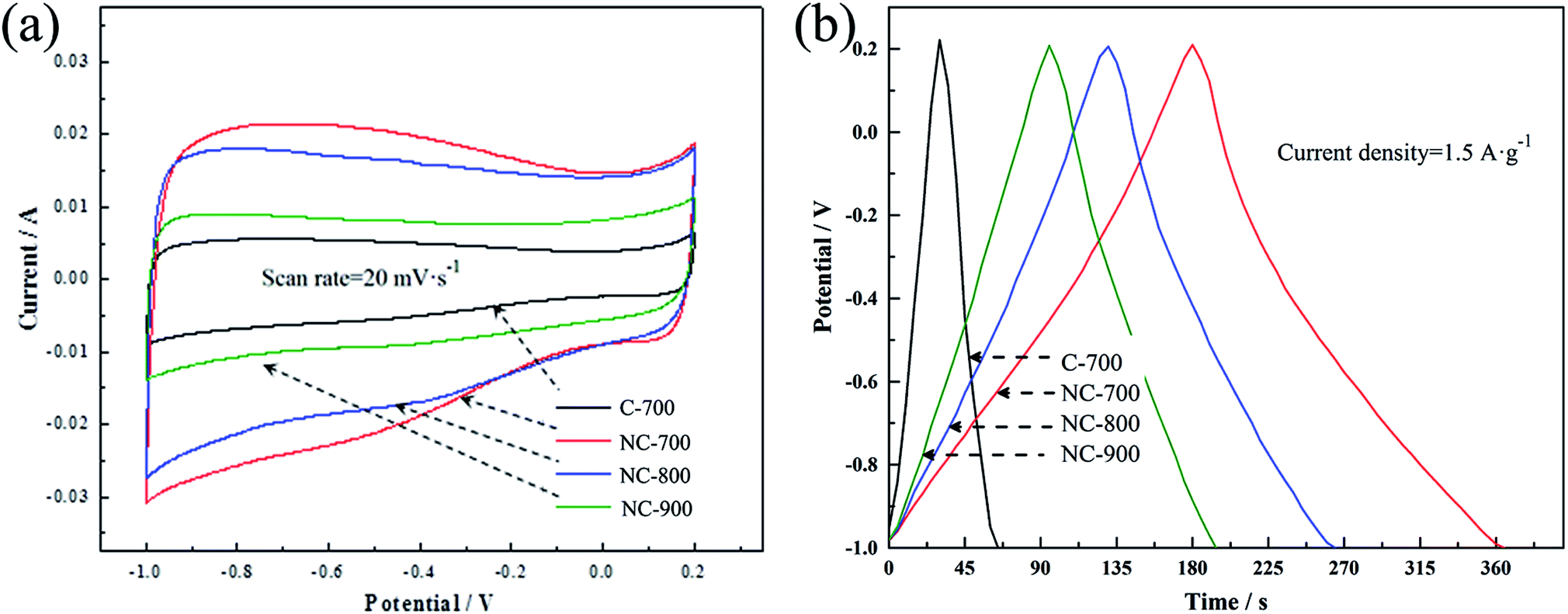 | ||
| Fig. 3 (a) CV curves of the samples at the scan rate of 20 mV s−1; (b) galvanostatic charge–discharge curves of the samples measured at the current density of 1.5 A g−1. | ||
CV curves of NC-700 at different scan rates from 5 mV s−1 to 100 mV s−1 are presented in Fig. 4(a). We can see that the slightly distorted rectangular have no obvious change even at high scan rate, demonstrating its good rate performance. The same conclusion can be obtained from the GCD results of the NC-700 tested at different current densities from 0.3 A g−1 to 10 A g−1 (Fig. 4(b)). Fig. 4(c) exhibits the rate performance of the NC-700 with different current densities from 0.3 A g−1 to 10 A g−1. The specific capacitance calculated from the GCD curve is 275 F g−1 at 0.3 A g−1, and retains 202 F g−1 at 10 A g−1 (the retention is as high as 73.5%). Such a good capacitance and rate performance is derived from the synergistic effect of porous structure and nitrogen doping: the mesopores facilitate electrolyte ion transport; the nitrogen doping provide pseudocapacitance and the functional groups can also improve the wettability of electrode material.35–37 The sample NC-700 also shows a good cycling performance at a current density of 10 A g−1 in Fig. 4(d). The specific capacitance retention after 10000 cycles is 98%.
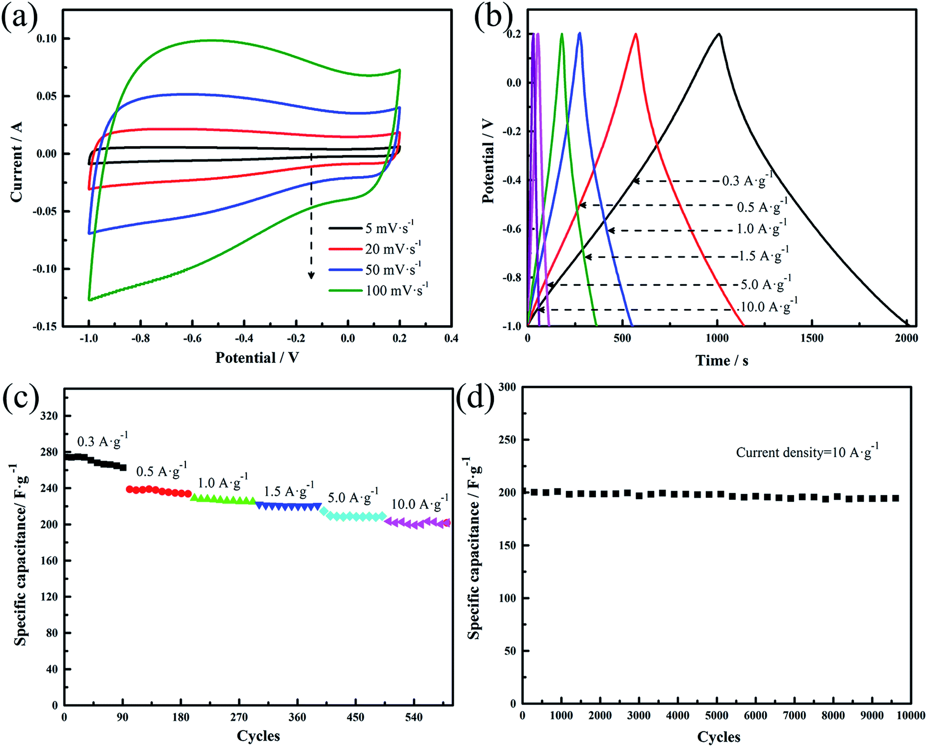 | ||
| Fig. 4 (a) CV curves of NC-700 at different scan rates; (b) galvanostatic charge–discharge curves of NC-700 at different current densities; (c) specific capacitance calculated by discharge curves at various current densities; (d) cycling life of NC-700 tested at a current density of 10 A g−1 in a three-electrode system. | ||
In order to further characterize the relationship between structure, chemical composition and electrochemical properties of the material, the electrochemical impedance spectroscopy (EIS) measurement was conducted shown in Fig. 5. The Nyquist plots of C-700 show that there is no obvious semicircle in correlation with the charge-transfer resistance.38 The approximate vertical line at low frequency region further demonstrates the good capacitive characteristics.39 In addition, the inset shows that there is a significant semicircle in the high frequency region of NC-700, and the semicircularity of the other samples is not significant, indicating that the NC-700 sample has a significant electrochemical reaction resistance and the most significant pseudo-capacitance behavior. As the carbonization temperature rises, NC-900 presents the most vertical line, that is, it delivers the best capacitive characteristics. Among all the samples, the C-700 shows the most vertical line, implying that the nitrogen doping is not advantageous to exhibit good capacitive characteristic due to the charge-transfer process.
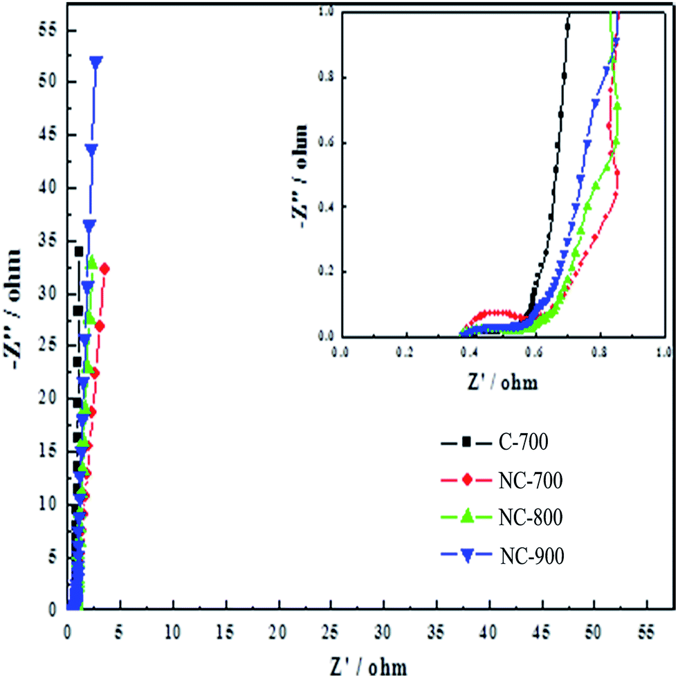 | ||
| Fig. 5 Nyquist plots of the carbon samples (the inset shows the amplified part of the Nyquist plots). | ||
4. Conclusions
In summary, nitrogen-doped porous carbon (NCs) were prepared by a facile method. Generally, EDTA and iron ion chelate can generate macromolecules. After adding melamine in the chelating process, the viscosity of macromolecules sol can retain melamine in the matrix during carbonation process, thus a nitrogen-doped porous carbon material was prepared. It was characterized by structural and electrochemical measurements, and the relationship between structure and electrochemical performance are discussed. The mesopores provide an favorable path for the electrolyte ion diffusion, allowing the electrolyte ions to be transported quickly during the charge–discharge process at large current densities. Moreover, the nitrogen doping has a considerable effect on the electrochemical performance and can provide additional pseudocapacitance. Consequently, the facile preparation method and synergistic effect between structure and nitrogen doping render NCs to be a promising candidate for supercapacitor application.Conflicts of interest
There are no conflicts to declare.Acknowledgements
We are grateful for the financial support from the National Natural Science Foundation of China (No. 51674221) and the Postgraduate Innovation Project of Hebei Province (No. CXZZBS2017058).References
- P. Simon, Y. Gogotsi and B. Dunn, Science, 2014, 343, 1210–1211 CrossRef CAS PubMed.
- Y. Wang, Y. Song and Y. Xia, Chem. Soc. Rev., 2016, 45, 5925–5950 RSC.
- J. Yan, Q. Wang, T. Wei and Z. Fan, Adv. Energy Mater., 2014, 4, 1300816 CrossRef.
- W. Yang, W. Yang, A. Song, L. Gao, G. Sun and G. Shao, J. Power Sources, 2017, 348, 175–182 CrossRef CAS.
- W. Yang, W. Yang, J. Feng, Z. Ma and G. Shao, Electrochim. Acta, 2016, 210, 71–78 CrossRef CAS.
- Y. Zhai, Y. Dou, D. Zhao, P. F. Fulvio, R. T. Mayes and S. Dai, Adv. Mater., 2011, 23, 4828–4850 CrossRef CAS PubMed.
- F. Béguin, V. Presser, A. Balducci and E. Frackowiak, Adv. Mater., 2014, 26, 2219–2251 CrossRef PubMed.
- J. Wang, H. L. Xin and D. Wang, Part. Part. Syst. Charact., 2014, 31, 515–539 CrossRef CAS.
- C. Zhu, T. Liu, F. Qian, T. Y.-J. Han, E. B. Duoss, J. D. Kuntz, C. M. Spadaccini, M. A. Worsley and Y. Li, Nano Lett., 2016, 16, 3448–3456 CrossRef CAS PubMed.
- Z. Chen, Z. Ma, J. Song, L. Wang and G. Shao, J. Power Sources, 2016, 324, 86–96 CrossRef CAS.
- A. Song, W. Yang, W. Yang, G. Sun, X. Yin, L. Gao, Y. Wang, X. Qin and G. Shao, ACS Sustainable Chem. Eng., 2017, 5, 3973–3981 CrossRef CAS.
- M. Zhao, H. Dong, Z. Chen, Z. Ma, L. Wang, G. Wang, W. Yang and G. Shao, Int. J. Hydrogen Energy, 2016, 41, 20485–20493 CrossRef CAS.
- S. Huo, P. Duan, T. Jiao, Q. Peng and M. Liu, Angew. Chem., Int. Ed., 2017, 56, 12174–12178 CrossRef CAS PubMed.
- W. Yang, W. Yang, A. Song, L. Gao, L. Su and G. Shao, J. Power Sources, 2017, 359, 556–567 CrossRef CAS.
- W. Yang, W. Yang, L. Kong, A. Song, X. Qin and G. Shao, Carbon, 2018, 127, 557–567 CrossRef CAS.
- J. Pu, C. Li, L. Tang, T. Li, L. Ling, K. Zhang, Y. Xu, Q. Li and Y. Yao, Carbon, 2015, 94, 650–660 CrossRef CAS.
- Y. Li, G. Wang, T. Wei, Z. Fan and P. Yan, Nano Energy, 2016, 19, 165–175 CrossRef CAS.
- G. Wang, Y. Sun, D. Li, H.-W. Liang, R. Dong, X. Feng and K. Müllen, Angew. Chem., 2015, 127, 15406–15411 CrossRef.
- H. Zhang, Y. Zhou, C. Li, S. Chen, L. Liu, S. Liu, H. Yao and H. Hou, Carbon, 2015, 95, 388–395 CrossRef CAS.
- K. Sun, E. Feng, H. Peng, G. Ma, Y. Wu, H. Wang and Z. Lei, Electrochim. Acta, 2015, 158, 361–367 CrossRef CAS.
- M. Zhou, F. Pu, Z. Wang and S. Guan, Carbon, 2014, 68, 185–194 CrossRef CAS.
- L. Wan, E. Shamsaei, C. D. Easton, D. Yu, Y. Liang, X. Chen, Z. Abbasi, A. Akbari, X. Zhang and H. Wang, Carbon, 2017, 121, 330–336 CrossRef CAS.
- J. Jiang, L. Bao, Y. Qiang, Y. Xiong, J. Chen, S. Guan and J. Chen, Electrochim. Acta, 2015, 158, 229–236 CrossRef CAS.
- W. Yang, Z. Du, Z. Ma, G. Wang, H. Bai and G. Shao, RSC Adv., 2016, 6, 3942–3950 RSC.
- F. Su, C. K. Poh, J. S. Chen, G. Xu, D. Wang, Q. Li, J. Lin and X. W. Lou, Energy Environ. Sci., 2011, 4, 717–724 CAS.
- W. Yang, W. Yang, F. Ding, L. Sang, Z. Ma and G. Shao, Carbon, 2017, 111, 419–427 CrossRef CAS.
- M. Thommes, K. Kaneko, A. V. Neimark, J. P. Olivier, F. Rodriguez-Reinoso, J. Rouquerol and K. S. Sing, Pure Appl. Chem., 2015, 87, 1051–1069 CrossRef CAS.
- Z. Li, Z. Xu, X. Tan, H. Wang, C. M. B. Holt, T. Stephenson, B. C. Olsen and D. Mitlin, Energy Environ. Sci., 2013, 6, 871–878 CAS.
- J. Wu, X. Zheng, C. Jin, J. Tian and R. Yang, Carbon, 2015, 92, 327–338 CrossRef CAS.
- Y. Mao, H. Duan, B. Xu, L. Zhang, Y. Hu, C. Zhao, Z. Wang, L. Chen and Y. Yang, Energy Environ. Sci., 2012, 5, 7950–7955 CAS.
- Y. Li, C. Lu, S. Zhang, F.-Y. Su, W. Shen, P. Zhou and C. Ma, J. Mater. Chem. A, 2015, 3, 14817–14825 CAS.
- T. Jawhari, A. Roid and J. Casado, Carbon, 1995, 33, 1561–1565 CrossRef CAS.
- L.-F. Chen, Z.-H. Huang, H.-W. Liang, H.-L. Gao and S.-H. Yu, Adv. Funct. Mater., 2014, 24, 5104–5111 CrossRef CAS.
- W. Yang, W. Yang, A. Song, L. Gao, L. Su and G. Shao, J. Power Sources, 2017, 359, 556–567 CrossRef CAS.
- H. Su, H. Zhang, F. Liu, F. Chun, B. Zhang, X. Chu, H. Huang, W. Deng, B. Gu, H. Zhang, X. Zheng, M. Zhu and W. Yang, Chem. Eng. J., 2017, 322, 73–81 CrossRef CAS.
- H. R. Byon, B. M. Gallant, S. W. Lee and Y. Shao-Horn, Adv. Funct. Mater., 2013, 23, 1037–1045 CrossRef CAS.
- Y. Zhang, T. Mori, J. Ye and M. Antonietti, J. Am. Chem. Soc., 2010, 132, 6294–6295 CrossRef CAS PubMed.
- P. Justin, S. K. Meher and G. R. Rao, J. Phys. Chem. C, 2010, 114, 5203–5210 CAS.
- D. Saha, Y. Li, Z. Bi, J. Chen, J. K. Keum, D. K. Hensley, H. A. Grappe, H. M. Meyer, S. Dai, M. P. Paranthaman and A. K. Naskar, Langmuir, 2014, 30, 900–910 CrossRef CAS PubMed.
| This journal is © The Royal Society of Chemistry 2017 |