 Open Access Article
Creative Commons Attribution 3.0 Unported Licence
Dielectric and current–voltage characteristics of flexible Ag/BaTiO3 nanocomposite films processed at near room temperature†
Seung Won
Kim‡
,
Hong Rak
Choi‡
,
Chan Su
Han‡
,
Da Bin
Kim
,
Ji Won
Kim
and
Yong Soo
Cho
 *
*
Department of Materials Science and Engineering, Yonsei University, Seoul 03722, Korea. E-mail: ycho@yonsei.ac.kr
First published on 12th December 2017
Abstract
High dielectric constant ceramic-polymer composite materials have been produced by thermal-treatment in the range of 160 to 200 °C. Here, we introduce a room temperature process of generating flexible high dielectric constant nanocomposite films on a polymer substrate by combining a printing technique with a UV-curing process. The composite structure is based on nanoscale BaTiO3 and Ag particles dispersed in a UV-cured polymer matrix. Dielectric characteristics of the nanocomposite thick films depended on the volume fraction and particle size of BaTiO3 as well as the content of Ag. As an optimal result, a dielectric constant of ∼300 and a dielectric loss of 0.08 were achieved when ∼81 nm BaTiO3 and ∼34 nm Ag particles were used in a total volume fraction of 56.2%, which are very competitive for flexible capacitive devices. Current–voltage behavior of the nanocomposite films depended largely on the content of Ag content as related to the percolative transition of electrical conduction.
1. Introduction
One of the important issues in flexible electronic packages is to adopt high dielectric constant εr materials suitable for various potential applications including communication, military and medical uses.1–3 The integration of the passive component into the flexible circuit board system requires very low-temperature processing and proper compatibility with a polymer substrate acting as a support for the electronic circuits. Generally, typical high εr materials, such as ferroelectric ceramics, are broadly used for electronic packaging components because of their promising dielectric properties.4–6 However, the ceramics produced by the common processing are brittle and require high-temperature treatment that is not suitable for flexible polymer substrates. The flexible substrates have often advantages over hard substrates in terms of shock resistance, solvent resistance, flexibility, low-cost metallization, etc.7,8 Many studies have been reported on high εr ceramic-polymer composites containing different ceramic fillers. Among high εr ceramic candidates, BaTiO3 and its modified compositions have been utilized more preferably for the high εr composites. Various polymers, such as epoxy resin, polyaniline, polyimide, cyclic olefin copolymer (COC), poly(vinylidene fluoride) (PVDF) or poly(vinylidene fluoridetrifluoroethylene) [P(VDF-TrFE)], have been reported to form a matrix phase effectively for dispersed BaTiO3 particles through a thermal-curing process in the typical temperature range of 160 to 200 °C.8–14 However, there are very limited reports dealing with the printing technology of the composite films, which simultaneously pursues the flexible system, requiring a very low temperature below 100 °C.This work introduces a composite-type thick film system based on a UV (ultra-violet)-curable polymer matrix incorporating dispersed Ag and BaTiO3 nanoparticles. There is no need for subsequent annealing process for densification because the UV-curing process occurs nearly at room temperature. Effects of metal nanoparticle incorporation in bulk BaTiO3-polymer composites have been well known as generating the beneficial increase of dielectric constant in the percolation-transition region while the dielectric loss depends on the type of composites and materials.15–17 Depending on the composite structure, the level of the increase of dielectric constant is determined. The embedded metal particles are known to produce extra interfacial polarization at the interfaces with the insulating matrix before the complete percolation occurs towards the metallic-like region.18,19
The primary purpose of this work suggests a flexible nanocomposite system processable at near room temperature for a polymer substrate. The effects of several parameters, such as volume fraction and particle size of the BaTiO3 filler and the content of Ag nanoparticles, on dielectric and current–voltage behaviors are investigated in this hybrid thick film system suitable for flexible capacitors. The incorporation of Ag into the BaTiO3-based dielectric nanocomposites has been reported in various forms of materials, such as bulk, nanofibers and thin films, requiring moderate or high temperature processing at >160 °C for densification.20–23 For example, the nanoscale Ag/BaTiO3 dispersed-PVDF bulk composites exhibited εr ∼ 160 at 1 kHz when processed by hot pressing at 180 °C.20 A composite film of Ag-coated BaTiO3 nanofiber-polymer was also reported to have εr ∼ 100 at 1 kHz.21 This work may be the very first report dealing with room temperature processing without using complex inorganic or organic precursors. As a promising result here, a dielectric constant of ∼303 with a low dielectric loss less than 0.1 was achieved for the ∼30 µm thick-nanocomposite films consisting of ∼81 nm BaTiO3 and ∼34 nm Ag nanoparticles dispersed in a UV-cured polymer matrix.
2. Experimental section
Three different commercial BaTiO3 powders having an average particle size of 3 µm (99% purity, Aldrich), 2 µm (99.5% purity, Aldrich) and 81 nm (99% purity, Aldrich) were thoroughly mixed with a commercially-available UV-curable organic vehicle (#3321, Loctite Co., USA) using a paste mixer (PDM-150, Daewha Tech, Korea) at 1200 rpm for 5 min to produce composite-type dielectric pastes. The components of UV polymer are N,N-dimethyl acrylamide, isobornyl acrylate, urethane acrylate oligomer, photoinitiator and organosilane ester. The content of BaTiO3 powder relative to the organic vehicle changed from 17.6 to 56.2 vol%. To incorporate Ag, commercial Ag nanoparticles (∼34 nm in average) were added by replacing the BaTiO3 filler from 5 vol% to 30 vol% only for the 56.2 vol% BaTiO3 sample. Accordingly, the 5 vol% Ag sample means a filler composition of 95 vol% BaTiO3 and 5 vol% Ag while the total volume fraction of fillers is fixed at 56.2 vol%. The maximum 30 vol% Ag was very close to the limited one in a practical sense for forming a viscous paste for printing. The dielectric pastes were then screen-printed on an ITO-coated polyethylene terephthalate (PET) substrate (Fine Chemicals Industry, Korea). For the UV-curing process, the printed paste was cured by direct exposure to a UV light having an intensity of 500 W for 10 min in a UV furnace (JHCI-051B, Jueun UV Tech, Korea). The thickness of UV-cured samples was about 30 µm, which can be controlled with the mesh size of screen and the viscosity of paste.Fig. 1(a) and (b) demonstrates the simple fabrication steps of the UV-curable processing with the schematic illustration of a flexible capacitor device structure composed of Ag/BaTiO3 nanoparticles in a UV-cured polymer matrix. The transmission electron microscopy (TEM, model G2 F20, Tecnai, FEI, USA) images of raw nanoparticle materials are seen in Fig. 1(c). The average sizes of the nanoscale BaTiO3 and Ag particles were determined as ∼81 nm and ∼34 nm, respectively. Microstructure of the composite thick films was observed by scanning electron microscopy (SEM, model S-4200, Hitachi, Nissei Sangyo, Japan). A patterned Pt top electrode was deposited by DC sputtering to make a sandwich structure for the dielectric measurement. Dielectric constant and loss tangent were measured at room temperature in the frequency range of 102–107 Hz by using an impedance analyzer (HP4194A, Hewlett-Packard, California, USA). Current–voltage characteristics were measured by using a semiconductor parameter analyzer (HP4145B, Hewlett-Packard, California, USA).
3. Results and discussion
3.1. Effects of the size and content of BaTiO3 particles
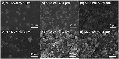
Fig. 2 shows the surface and cross-sectional SEM images selected to demonstrate the effects of different content and particle size of the BaTiO3 filler on microstructure evolution with the curing process. The surface images of Fig. 2(a)–(c) show dispersed BaTiO3 particles in the polymer matrix without significant voids or pores. Relatively uniform distribution of the filler particles can be seen from the surface microstructures. It seems that the curing time of 10 min is good enough for effective curing which is associated with the progress of photo-oxidation of urethane bridges into a quinone-imide structure.24,25 Our commercial UV polymer is based on acrylated urethane with a high sensitivity to curing time. Compared to the film of 17.6 vol% BaTiO3 (Fig. 2(a)), the composite with 56.2 vol% BaTiO3 demonstrates more filler particles distributed uniformly (Fig. 2(b)). The UV polymer wets the surface of particles effectively and then forms a matrix network upon the short curing process.9,10 Clearly, the nanoscale particle size of 81 nm at the identical 56.2 vol% seemed to bring somewhat different microstructural features as shown in Fig. 2(c). More finely dispersed BaTiO3 nanoparticles are easily seen in the surface image. Cross-sectional microstructures of Fig. 2(d)–(f) exhibit the similar trends with the features observed in the surface ones except that the interior of the films tends to show less densified states than the surfaces. Probably the curing process more dominantly happens over the surface since a short duration of curing is used. As a clear example, Fig. 2(e) shows a considerable portion of porosity as a result of insufficient wetting of the polymer onto the filler particles. We evaluated quantitatively the level of porosity using an image analysis from the cross-sectional microstructures of Fig. 2(d–f) as shown in Fig. S1 of the ESI.† The image analysis may not represent the true number of porosity. According to the estimation, the 56.2 vol% 3 µm sample (Fig. 2(e)) showed the largest porosity of ∼12.8% while the 56.2 vol% 81 nm sample had a porosity of ∼3.7%.Fig. 3 shows the dependence of BaTiO3 content on dielectric constant and loss of the thick films with different particle sizes of 81 nm, 2 µm and 3 µm, which were measured at 1 kHz. The dielectric constant of all composite films increased with the content of BaTiO3. The increasing tendency of dielectric constant with increasing the relative content of BaTiO3 was more prominent in the case of 81 nm particle size. Dielectric constant reached to ∼36.4 at 56.2 vol% BaTiO3 when the smallest particle size of 81 nm was used. There have been similar reports where the smaller particle size creates more homogeneous matrix and the larger dielectric constant in ceramic-polymer composites by creating a larger surface area for effective polarization.26–28 The improvement of dielectric constant is also associated with better density and dispersion of the particles in the polymer matrix.
 | ||
| Fig. 3 Variations of (a) dielectric constant and (b) dielectric loss as a function of BaTiO3 content for the samples with different average particle size of BaTiO3 filler. | ||
Dielectric loss was also found to depend on particle size and volume fraction of the filler as shown in Fig. 3(b). The loss values were quite stable over the filler volume change, with the increasing tendency of the loss with the increase of filler. The increasing tendency must be associated with the creation of more effective interfaces between the filler and polymer matrix, where the interface-driven dielectric loss is produced dominantly.11,29,30 The smaller particle size tends to produce the lower values of dielectric loss. Generally a loss value of less than 0.1 is preferred in the capacitive applications. It is assumed that the well-dispersed fillers with less porosity in the 81 nm case contribute to the reduction of dielectric loss from the highly leaky polymer.
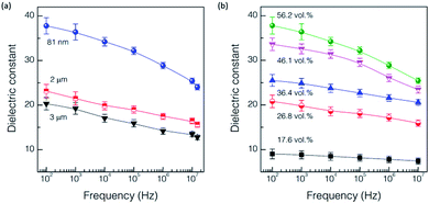
Fig. 4(a) shows the frequency dependence of dielectric constant for the samples having different particle sizes but containing the same content of 56.2 vol% BaTiO3. The smaller particle size exhibited the stronger dependence of dielectric constant on frequency, with higher dielectric constants at the same frequency. As expected from the frequency dependence of dielectric constant in intrinsic BaTiO3,31 all the three samples showed similar decreasing tendency of dielectric constant over the frequency range from 102 to 107 Hz. Less sensitive dependence of frequency with the larger particle size is anticipated due to less contribution of BaTiO3 to polarization degradation with higher frequency as reported in the study of other BaTiO3-polymer composites.10,26 Fig. 4(b) shows another frequency dependence of dielectric constant, which were obtained for the samples containing the same particle size of 81 nm but having different volume fraction of BaTiO3 filler in the identical frequency range. Dielectric constant was found to decrease gradually with increasing the frequency, which depends on the volume fraction. The larger volume of filler tended to induce a larger drop of dielectric constant with increasing frequency. Thick films with a larger volume of BaTiO3 follow more closely the relaxation behavior of BaTiO3 itself. The polymer is likely to have very weak dependency of frequency from the least polarization in this frequency range.
The mechanical integrity of the flexible samples was evaluated by applying the bending stress and then measuring dielectric properties under the bending strain as shown in Fig. S2.† As anticipated, the variations of dielectric constant and loss are well maintained up to the strain level of ∼1.7%. It suggests that the UV-cured composite films are very competitive in the flexible environment, without creating significant fracture. Typically, the inorganic thin films of a few hundreds of nm in thickness can withstand the bending strain of only ∼1.0% without causing the mechanical damage.32,33
In addition, the estimated dielectric behaviors of the samples according to several dielectric prediction models can be referred to Fig. S3.† It suggests that the effective medium theory (EMT) model is well suited for the estimation of effective dielectric constant variations of the nanocomposites with the particle size of BaTiO3 filler.
3.2. Effects of dispersed Ag nanoparticles in nanocomposite films
The addition of Ag nanoparticles for the 56.2 vol% 81 nm BaTiO3 nanocomposite thick films was investigated in regard with the effects of dielectric and current–voltage behavior. The dispersion of Ag nanoparticles was found to be recognizable as represented in the surface SEM image of the maximum 30 vol% Ag case with the elemental mapping in Fig. S4.† Fig. 5 shows the frequency dependence of dielectric constant and loss in the BaTiO3 thick films partially substituted with the Ag nanoparticles, which were measured at 1 kHz. As expected, the dielectric constant tends to increase gradually with increasing the volume fraction of Ag nanoparticle by reaching ∼303 with the 30 vol% Ag, suggesting the percolation transition with a higher content of Ag.15,18 The increase is very substantial compared to the value of ∼36.4 for the sample without Ag. It seems that the Ag nanoparticles are surrounded by the polymer matrix and thus their conductive paths are confined in the composite structure up to the maximum of 30 vol% Ag.18,19 It is very noticeable that the dielectric loss values were maintained at the level of <0.1 regardless of Ag content (Fig. 5(b)).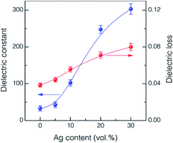 | ||
| Fig. 5 Variations of dielectric constant and loss at 1 kHz as a function of Ag content for the UV-cured 56.2 vol% 81 nm BaTiO3 nanocomposite thick films. | ||
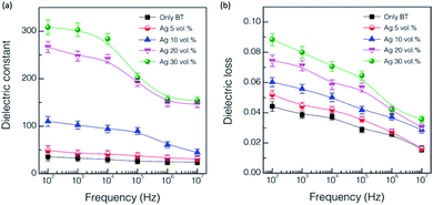
Fig. 6 shows the frequency dependence of dielectric constant and loss values for the UV-cured nanocomposite thick films incorporating different contents of Ag nanoparticles. The dielectric constant of the thick films tends to be reduced as the frequency increases regardless of the level of Ag incorporation. The thick films having high contents of Ag, such as 20 and 30 vol%, exhibited the distinct behavior of dielectric relaxation in the frequency range of 104 to 106, which follow the typical relaxation behavior of BaTiO3.16 The frequency dependence of dielectric loss in Fig. 6(b) is also the anticipated one as it shows the decreasing tendency with increasing frequency depending on the content of Ag in the thick films. The dependency of frequency becomes larger with the increase of Ag content.
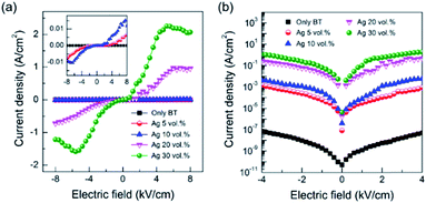
Fig. 7 shows the plots of current density with applied electric field for the samples having different contents of Ag nanoparticles. The current density with electric field was dependent on the content of Ag. The current density is minimal up to the content of 10 vol% Ag as seen in the inserted highlighted plots of Fig. 7(a), while the increased content of Ag above 20 vol% demonstrates the considerable current density created even with a small electric field. The estimated leakage current density increased gradually from 4.6 × 10⁻⁷ A cm−2 for no Ag sample to ∼2.11 A cm−2 for the 30 vol% Ag sample (Fig. 7(b)). The observed dependence of the leakage current on the content of Ag nanoparticles is reasonable when considered that the incorporated Ag acts as an electrical channel with the increase of electric field.18,19 It is likely that a higher packing density of the composite thick films is critical in reducing the leakage current density.
We compared the current performance with reported composite cases consisting of BaTiO3 and metal nanoparticles in various forms of bulk and thin film as shown in Fig. 8. Ideally, a higher dielectric constant and a lower dielectric loss are preferred as highlighted with the shaded circle. Our results are close enough to the ideal region by demonstrating the dielectric constant of ∼303 with a loss of ∼0.08. The composite cases with higher εr than our value are based on thermally cured bulk samples heat-treated at 160 to 200 °C.15,17,34 The yellow highlighted region in the left bottom region of Fig. 8 corresponds to the BaTiO3-based composite examples not containing percolative metal particles,10,35–37 which can be characterized with low dielectric constant with acceptable dielectric loss. The current result may be meaningful in that a dielectric constant of >300 with a dielectric loss of <0.1 is achievable by a very simple experimental procedure of screen-printing and room-temperature curing on a flexible polymer substrate.
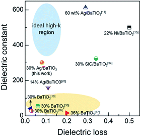 | ||
| Fig. 8 Comparisons of the dielectric constant and loss of the current work with the reported values of the representative BaTiO3-based high εr polymer composites having various forms and thickness: 100 µm-thick thin wafer in ref. 10, 1 mm-thick pellets in ref. 15, 17 and 20, 500 µm-thick pellet in ref. 34, 25 µm-thick cast film in ref. 35, 55–75 µm-thick cast film in ref. 36, and spin-coated film (no thickness information) in ref. 37. | ||
4. Conclusions
A nonconventional way was introduced to produce flexible high εr nanocomposite thick films at near room temperature by using the UV-curing process for formation of a polymer-based matrix. The dense composite film structure of ∼30 µm in thickness was obtained by screen-printing on a PET substrate and then by the UV-curing process at near room temperature only for 10 min. Different particle sizes of BaTiO3 from 81 nm to 3 µm were evaluated to pursue the optimal dielectric constant, with the variations of the volume fraction of the filler up to 56 vol%. A smaller size of BaTiO3 filler was beneficial in producing better dielectric performance. The combination of ∼81 nm BaTiO3 and ∼34 nm Ag nanoparticles for the printable composite thick films resulted in a dielectric constant of ∼300 and a dielectric loss of 0.08. Current–voltage curves of the nanocomposite films suggested the dependence of Ag content on electrical leakage current behaviour.Conflicts of interest
There are no conflicts to declare.Acknowledgements
This work was financially supported by a grant (NRF-2016M3A7B4910151) of the National Research Foundation of Korea and also by the Industrial Strategic Technology Development Program (#10079981) funded by the Ministry of Trade, Industry & Energy (MOTIE) of Korea. We also acknowledge Dr Koppole C. Sekhar for his initial contribution to this work.References
- J. K. Yuan, J. W. Zha, T. Zhou, S. T. Li and G. H. Hu, Prog. Mater. Sci., 2001, 57, 660–723 Search PubMed.
- J. Huang, J. Liao, P. Wang, W. Zhang, X. Wei and Z. Xu, Surf. Coat. Technol., 2014, 251, 307–312 CrossRef CAS.
- H. R. Choi, K. C. Sekhar, A. Cho and Y. S. Cho, Int. J. Appl. Ceram. Technol., 2016, 13, 685–689 CrossRef CAS.
- A. Piegat, M. E. Fray, H. Jawad, Q. Z. Chen and A. R. Boccaccini, Adv. Appl. Ceram., 2008, 107, 287–291 CrossRef CAS.
- S. H. Key, D. W. Lee, J. W. Jung, B. K. Kim and Y. S. Cho, J. Alloys Compd., 2012, 530, 40–47 CrossRef CAS.
- B. K. Kim, D. W. Lee, S. H. Key, T. J. Cho, S. M. Jeong, K. J. Kim, M. S. Jeon, J. K. Song and Y. S. Cho, J. Am. Ceram. Soc., 2010, 93, 2334–2338 CrossRef CAS.
- J. Malecki and B. Hilczer, in Ferroelectric Polymers and Ceramic-Polymer Composites, Trans Tech Publications, ed. D. K. D. Gupta, Switzerland, 1994, ch. 7, pp. 181–216 Search PubMed.
- L. Ren, X. Meng, J. Zha and Z. Dang, RSC Adv., 2015, 5, 65167–65174 RSC.
- C. K. Chiang, R. Popielarz and L. P. Sung, Mater. Res. Soc. Symp. Proc., 2001, 682, N6.9 CrossRef.
- R. Popielarz, C. K. Chiang, R. Nozaki and J. Obrzut, Macromolecules, 2001, 34, 5910–5915 CrossRef CAS.
- T. Hu, J. Juuti, H. Jantunen and T. Vilkman, J. Eur. Ceram. Soc., 2007, 27, 3997–4001 CrossRef CAS.
- K. Suematsu, M. Arimura, N. Uchiyama, S. Sata and T. Makino, RSC Adv., 2015, 6, 20807–20813 RSC.
- M. Lin, V. K. Thakur, E. J. Tan and P. S. Lee, RSC Adv., 2011, 1, 576–578 RSC.
- Y. Kobayashi, T. Tanase, T. Tabata, T. Miwa and M. Konno, J. Eur. Ceram. Soc., 2008, 28, 117–122 CrossRef CAS.
- Z. M. Dang, Y. Shen and C. W. Nan, Appl. Phys. Lett., 2002, 81, 4814–4816 CrossRef CAS.
- C. Pecharroman, F. E. Betegon, J. F. Bartolome, S. L. Esteban and J. S. Moya, Adv. Mater., 2001, 13, 1541–1544 CrossRef CAS.
- S. Luo, S. Yu, F. Fang, M. Lai, R. Sun and C. P. Wong, Appl. Phys. Lett., 2014, 104, 252903 CrossRef.
- Y. Shen, Z. Yue, M. Li and C. W. Nan, Adv. Funct. Mater., 2005, 15, 1100–1103 CrossRef CAS.
- Y. Shen, Y. Lin, M. Li and C. W. Nan, Adv. Mater., 2007, 19, 1418–1422 CrossRef CAS.
- S. Luo, S. Yu, R. Sun and C. P. Wong, ACS Appl. Mater. Interfaces, 2014, 6, 176–182 CAS.
- H. Liu, S. Luo, S. Yu, S. Ding, Y. Shen, R. Sun and C. Wong, IEEE Trans. Dielectr. Electr. Insul., 2017, 24, 757–763 CrossRef.
- J. Chen, X. Yu, F. Yang, Y. Fan, Y. Jiang, Y. Zhou and Z. Duan, J. Mater. Sci.: Mater. Electron., 2017, 28, 8043–8050 CrossRef CAS.
- C. Baek, J. H. Yun, J. E. Wang, C. K. Jeong, K. J. Lee, K. Park and D. K. Kim, Nanoscale, 2016, 8, 17632–17638 RSC.
- C. Decker and K. Zahouily, Polym. Degrad. Stab., 1999, 64, 293–304 CrossRef CAS.
- J. W. Jang, J. S. Kim, O. H. Kwon, T. H. Lee and Y. S. Cho, Opt. Lett., 2015, 40, 3723–3726 CrossRef CAS PubMed.
- T. Yamamoto, K. Urabe and H. Banno, Jpn. J. Appl. Phys., 1993, 32, 4272–4276 CrossRef CAS.
- Z. M. Dang, Y. H. Lin and C. W. Nan, Adv. Mater., 2003, 15, 1625–1628 CrossRef CAS.
- H. G. Lee and H. G. Kim, J. Appl. Phys., 1990, 67, 2024–2028 CrossRef CAS.
- R. Popielarz and C. K. Chiang, Mater. Sci. Eng., B, 2007, 139, 48–54 CrossRef CAS.
- G. Subodh, M. Joseph, P. Mohanan and M. T. Sebastian, J. Am. Ceram. Soc., 2007, 90, 3507–3511 CrossRef CAS.
- M. P. McNeal, S. J. Jang and R. E. Newnham, J. Appl. Phys., 1998, 83, 3288–3297 CrossRef CAS.
- H. R. Choi, S. K. Eswaran, S. M. Lee and Y. S. Cho, ACS Appl. Mater. Interfaces, 2015, 7, 17569–17572 CAS.
- B. C. Mohanty, H. R. Choi, Y. M. Choi and Y. S. Cho, J. Phys. D: Appl. Phys., 2011, 44, 025401 CrossRef.
- Y. Li, X. Huang, Z. Hu, P. Jiang, S. Li and T. Tanaka, ACS Appl. Mater. Interfaces, 2011, 3, 4396–4403 CAS.
- J. Li, J. Claude, L. E. N. Franco, S. I. Seok and Q. Wang, Chem. Mater., 2008, 20, 6304–6306 CrossRef CAS.
- T. Zhou, J. W. Zha, R. Y. Cui, B. H. Fan, J. K. Yuan and Z. M. Dang, ACS Appl. Mater. Interfaces, 2011, 3, 2184–2188 CAS.
- Y. Kobayashi, A. Kurosawa, D. Nagao and M. Konno, Polym. Eng. Sci., 2009, 49, 1069–1075 CAS.
Footnotes |
| † Electronic supplementary information (ESI) available. See DOI: 10.1039/c7ra11640c |
| ‡ Equally contributed. |
| This journal is © The Royal Society of Chemistry 2017 |


