 Open Access Article
Creative Commons Attribution 3.0 Unported Licence
Antifouling sulfonated polyamide nanofiltration hollow fiber membrane prepared with mixed diamine monomers of BDSA and PIP
Ben-Qing Huanga,
Zhen-Liang Xu a,
Hao Dinga,
Ming-Che Miaob and
Yong-Jian Tang
 *a
*a
aState Key Laboratory of Chemical Engineering, Membrane Science and Engineering R&D Lab, Chemical Engineering Research Center, East China University of Science and Technology, 130 Meilong Road, Shanghai 200237, China. E-mail: tangyongjian@ecust.edu.cn; Fax: +86-21-64252989; Tel: +86-21-64253670
bJiangsu Zhenjiang Research Institute of Building Science Group CO., LTD, 8 Tanshan Road, ZhenJiang 212000, China
First published on 15th December 2017
Abstract
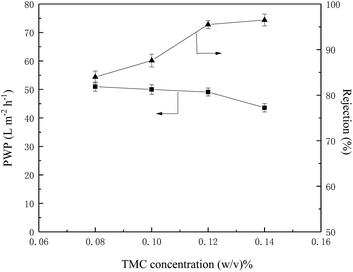
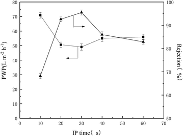
A novel high-flux sulfonated polyamide nanofiltration (NF) hollow fiber membrane was made from the mixed monomers of 2,2′-benzidinedisulfonic acid (BDSA) and piperazine (PIP). By optimizing the preparation parameters (TMC concentration, reaction time and BDSA/PIP mixing ratio), the optimized NF membrane possessed a pure water permeability (PWP) of 49.1 L m−2 h−1 and a Na2SO4 rejection of 95.5% under 4 bar. The molecular weight cut off (MWCO) of the BDSA/PIP NF membrane was about 400 Da. Furthermore, in a long-term antifouling test with 0.3 g L−1 bovine serum albumin (BSA) solution, the total flux decline rate (FDR) and the flux recovery ratio (FRR) of the membrane were 16.7% and 85.7% respectively, which indicated the good antifouling properties and application prospects of the TFC NF membrane.
1. Introduction
The requirement for clean water is expanding due to worsening water pollution and growing global population. Membrane technology has great potential for the application in water treatment and purification owing to its high efficiency as well as low energy consumption. Nanofiltration (NF), in which the molecular weight cut off (MWCO) for neutral organics is ranging from 150 to 2000 Da,1 possesses unique advantages in separating divalent salts and low-molecular-weight organic from water compared with other pressure driven membranes such as ultrafiltration (UF) and reverse osmosis (RO). As a result, NF has broad application in desalination of seawater, reuse of sewage, food production, pharmaceutical and biotechnology industries. Interfacial polymerization (IP) is the most ordinary way to fabricate the thin-film composite (TFC) NF membranes while piperazine (PIP) and trimesoyl chloride (TMC) are the most widely used monomers in aqueous and organic phases, respectively.2 For the sake of better performance, many novel monomers are used to fabricate TFC membranes because the monomer has a decisive effect on membrane properties. Cheng et al.3 prepared a TFC membrane with amino-functional polyethylene glycol (PEG) and TMC by the IP process. The TFC membrane showed a pure water flux of 66.0 L m−2 h−1 at 5 bar as well as good fouling resistance. Tang et al.4 fabricated TFC NF membranes with high chlorine-tolerant properties using mixed aqueous monomers of PIP and 2,2′-bis(1-hydroxyl-1-trifluoromethyl-2,2,2-trifluoroethyl)-4,4′-methylenedianiline (BHTTM). Furthermore, after pre-oxidation with NaClO, the NF membrane achieved an ultra-high permeability of 161 L m−2 h−1 while Na2SO4 rejection remained 92.1%.5To satisfy the demand of industrial application, the poor fouling resistance of TFC NF membranes in long-time running must be resolved. The fouling occurs when foulants accumulate on the membrane surface and internal pores, leading to the permeability and rejection decline irreversibly. Antifouling property of membranes is closely related to surface roughness, electrostatic charges and hydrophilicity.6 Enhancing the hydrophilicity of membrane is a propitious method to heighten the antifouling property due to the hydrophobicity of many foulants and a thin water layer in the hydrophilic top layer is effective to keep the foulants from cumulating on the membrane.7 The highly hydrophilic TFC membranes can be fabricated by using hydrophilic monomers2,8,9 or blending inorganic nanoparticles.10–14 Nevertheless, poor dispersity and aggregation of nanoparticles as well as the weak compatibility between polymer materials and inorganic nanoparticles limits the application of nanoparticles in fabricating TFC membrane.15 It is simple and effective to prepare high-performance TFC NF membranes by using hydrophilic monomers. Li et al.16 fabricated a sulfonated TFC membrane using 2,2′-benzidinedisulfonic acid (BDSA) and TMC which showed good application prospect in desalination of dye wastewater. The flux recovery ratio (FRR) of the membrane was 95.6% after washed with 20% alcohol solution, which indicated good antifouling property. Lv et al.17 synthesized a novel sulfonated aromatic diamine monomer, potassium 2,5-bis(4-aminophenoxy)benzenesulfonate (BAPBS) to polymerize with TMC and the TFC membrane manifested good antifouling characteristics as well as high flux of 72.8 L m−2 h−1 at 6 bar. Weng et al.18 prepared three NF membranes using different aqueous monomers (PIP, N-aminoethyl piperazine (AEP) and zwitterionic N-aminoethyl piperazine propane sulfonate (AEPPS) respectively) and contrasted the membrane structure and performance, finding that the membrane prepared by AEPPS showed outstanding antifouling property and high flux of 80.3 L m−2 h−1 which was 3.8 and 8.1 times of the membranes made by AEP and PIP owing to its preeminent hydrophilicity and smooth surface structure.
In this work, using BDSA and PIP as aqueous monomers and TMC as organic monomer, TFC hollow fiber NF membrane was fabricated by IP. The structure and physicochemical characteristics of the NF membranes were analyzed by SEM, AFM, XPS and water contact angle. The separation properties of the NF membranes were analyzed by different salts and neutral organics. In addition, the antifouling performance was investigated through a long-term testing of bovine serum albumin (BSA).
2. Experimental
2.1 Materials
PES (polyethersulfone, Mw = 58 kDa) was purchased from BASF company. N,N-Dimethylacetamide (DMAc, AR) was obtained from Xilong Scientific Co., Ltd. 2,2′-Benzidinedisulfonic acid (BDSA, >70%) was provided by TCI (Shanghai) Development Co., Ltd. Trimesoyl chloride (TMC, ≥98%) was purchased from Qingdao Benzo Chemical Company (China). Inorganic salts including: Na2SO4, MgSO4, MgCl2, NaCl, sodium hydroxide (NaOH, AR), n-butyl alcohol (AR), glucose (AR), sucrose (AR), raffinose (AR), bovine serum albumin (BSA, AR), diethylene glycol (DEG, AR), piperazine (PIP, GR) and n-hexane (AR) were purchased from Sinopharm Chemical Reagent Co. Ltd (China).2.2 Preparation of PES hollow fiber UF membranes
The hollow fiber UF membranes were self-made in lab via using non-solvent induced phase inversion (NIPS) technique according to our previous report.19 The detailed spinning parameters were listed in Table 1. The dope solution contained a certain proportion of PES, DMAc and DEG was stirred by a magnetic stirrer for 12 hours and degassed overnight before spinning. The dope solution and bore fluid were pushed by nitrogen through the spinneret with the certain flow rates controlled by different pumps and the extruded membranes dropped into DI water by gravity for phase separation. The prepared hollow fiber membranes were immersed in DI water for 5 days to remove the residual solvents. The MWCO and PWP of the PES hollow fiber UF membranes were 70![[thin space (1/6-em)]](https://www.rsc.org/images/entities/char_2009.gif) 000 Da and 150 L m−2 h−1 bar−1, respectively.
000 Da and 150 L m−2 h−1 bar−1, respectively.
| Dope solution (wt%) | PES/DMAc/DEG (17![[thin space (1/6-em)]](https://www.rsc.org/images/entities/char_2009.gif) : :![[thin space (1/6-em)]](https://www.rsc.org/images/entities/char_2009.gif) 43 43![[thin space (1/6-em)]](https://www.rsc.org/images/entities/char_2009.gif) : :![[thin space (1/6-em)]](https://www.rsc.org/images/entities/char_2009.gif) 40) 40) |
| Dope flow rate (mL min−1) | 5 |
| Bore fluid composition | DI water |
| Bore fluid flow rate (mL min−1) | 1.2 |
| External coagulant | DI water |
| Air gap (cm) | 0 |
| Nitrogen pressure (bar) | 1.5 |
| Dimension of spinneret (mm) | ID/OD = 1.4/0.7 |
| Spinneret temperature (°C) | 25 |
2.3 Preparation of TFC hollow fiber NF membranes
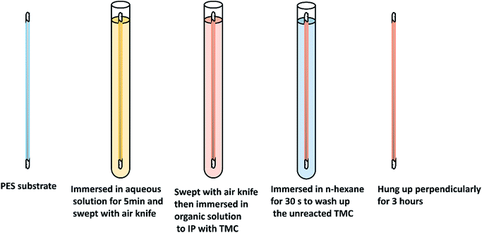
A series of aqueous solutions containing different ratios of PIP/BDSA (the total monomer concentration was 1% w/v and the concentration of NaOH was 0.05 mol L−1), and organic phase solutions with different concentration of TMC in n-hexane were prepared. The UF hollow fiber membranes were taken out of the DI water and both ends were sealed up to prevent the polymerization in the inwall of the hollow fiber membranes. The preparation process of TFC NF membrane was interpreted in Fig. 1. Firstly, the UF membrane was immersed in aqueous phase for 5 min after the water drops on the outside surface were blown away by an annular air knife. Then removed the droplets once again and immersed the membrane in organic phase for a certain time. After that, the membrane was immersed in n-hexane for 30 s to wash up the unreacted TMC. Finally, the NF membrane was hung up perpendicularly for 3 hours for the further polymerization.2.4 Membrane characterization
![[thin space (1/6-em)]](https://www.rsc.org/images/entities/char_2009.gif) 000× magnification times. The samples were coated with gold before the SEM analysis.
000× magnification times. The samples were coated with gold before the SEM analysis.2.5 Nanofiltration performance of NF membranes
Pure water flux was measured by using a lab-scaled stainless steel module. In each experiment, three modules were prepared under the same condition and tested in three identical cross-flow set-ups with feed solutions circulated to make sure of the data reliability. The hydraulic pressure of feed solution was controlled through valves and the permeate solution was collected. Permeate solutions were collected after deionized water circulating for 30 min under certain pressure. The computational formula of pure water permeability (PWP) was displayed as follow:
 | (1) |
In the same way, the rejection performance was investigated with a series of salt solution (Na2SO4, MgSO4, MgCl2 and NaCl, 2000 ppm) and various neutral organic solutions (n-butyl alcohol, glucose, sucrose and raffinose, 300 ppm).
The solute rejection was calculated according to following formula:
 | (2) |
The MWCO of TFC NF membrane was evaluated by the rejection experiment of neutral organics and the molecular weight (Mw) of the solute which rejection was 90% was considered as the MWCO of the TFC membrane. The mean pore size and pore size distribution were evaluated with a log-normal model using MATLAB. The Stokes radius (rs) was related with the probability of rejection and the geometrical mean radius of organic solute (μs) was obtained at R = 50%. The ratio of rs at R = 84.13% to that at R = 50% was defined as the geometrical standard deviation (σs). The mean pore radius (μp) and pore size distribution (σp) were the same as μs and σs, respectively. The relationship between rejection of membrane and probability of rejection was calculated with the follow equation:
 | (3) |
2.6 Antifouling estimation of TFC NF membrane
To investigate the antifouling property of TFC NF membranes, a long-term testing was carried out with a BSA solution (0.3 g L−1, pH 7.0) and the pressure was maintained at 4 bar. The experiment was implemented for three cycles. In each cycle, the DI water was filtrated through the membrane module for 4 hour, then the feed converted into BSA solution and operated for 8 hour and the permeability was recorded every hour. After three cycles test, the BSA solution was replaced with pure water, and the flux recorded over the following 4 hour.Fouling caused by reversible resistances (Rr) and irreversible resistances (Rir) was described by the following equation:
 | (4) |
 | (5) |
The total flux decline rate (FDR) and the flux recovery ratio (FRR) of the NF membrane after long-term testing was calculated according to the following equation:
 | (6) |
 | (7) |
3. Results and discussions
3.1 Composition of the top surface of the NF membranes
The chemical composition of the PES substrate and NF membranes was analyzed by XPS with range of 3–10 nm. Fig. 2 and Table 2 showed the XPS spectrum and the atom percent of the PES substrate and three TFC NF membranes, respectively. From the wide-scan spectra, nitrogen could be detected on the surface of TFC NF membranes, which indicating the polyamide layer was generated. There was a spot of sulfur on the top surface of the BDSA NF membrane which was similar to the result of Hu et al.20 However, the peak of sulfur didn't exist in the spectrogram of the BDSA/PIP NF membrane. This may be explained that “–SO3H” was covered by the polymer chain as a result of interaction between BDSA and PIP. For the low molecular weight of PIP, it could permeate through the polyamide layer and continue to react with TMC, thus the “–SO3H” in the cross-linking chain was covered probably.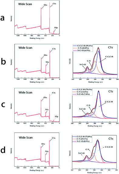 | ||
| Fig. 2 XPS wide scan and C1 score-level of (a) the PES substrate, (b) the PIP NF membrane, (c) the BDSA NF membrane and (d) the BDSA/PIP NF membrane. | ||
| Sample | Atom percent (%) | |||
|---|---|---|---|---|
| C 1s | N 1s | O 1s | S 2p | |
| PIP | 73.83 | 11.46 | 14.71 | 0 |
| BDSA | 67.53 | 6.99 | 23.17 | 2.31 |
| BDSA/PIP | 73.04 | 11.91 | 15.05 | 0 |
The amount of carbon–carbon bond (C–C) and carbon–hydrogen (C–H) was equal to the area of the peak at 285.1 eV. The peak at 286.1 eV represented the carbon–nitrogen bond (C–N) which belonged to the unreacted amine in the aqueous phase. The content of amido bond (N–C![[double bond, length as m-dash]](https://www.rsc.org/images/entities/char_e001.gif) O) illustrated the degree of polymerization.13 From the C1 score level spectra, the amido bond percent of the membrane prepared by mixed amine was larger than that of the PIP NF membrane and the BDSA NF membrane, indicating that the BDSA/PIP NF membrane hold a denser polyamide layer. The TFC membrane made from mixed amines hold a denser polyamide layer owing to the synergism effect between PIP and BDSA.21 For the mixing with BDSA, the polyamide backbone stiffness was enhanced. Therefore, the separation performance was improved.
O) illustrated the degree of polymerization.13 From the C1 score level spectra, the amido bond percent of the membrane prepared by mixed amine was larger than that of the PIP NF membrane and the BDSA NF membrane, indicating that the BDSA/PIP NF membrane hold a denser polyamide layer. The TFC membrane made from mixed amines hold a denser polyamide layer owing to the synergism effect between PIP and BDSA.21 For the mixing with BDSA, the polyamide backbone stiffness was enhanced. Therefore, the separation performance was improved.
3.2 Morphology of the NF membranes
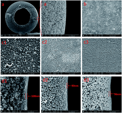
Fig. 3 showed the morphologies of the top surfaces and cross sections of the PES substrate and TFC NF membranes. The image of PES substrate showed obvious sponge-like structure which was similar with the result in previous literatures and the spongy-like structure could provide appropriate pore size for IP progress and higher strength for high pressure operation.22,23 As shown in (c1), asymmetrical nodular structure could be observed in the surface of the PIP NF membrane which could be ascribed that the PIP with small molecular weight was easy to pass through the polyamide layer and react with TMC quickly forming aggregate in the top surface.24 The BDSA NF membrane had large ravines and gullies in the top surface while the BDSA/PIP NF membrane was smoother than the PIP NF membrane and the BDSA NF membrane. From (d1)–(d3), it could be observed that all the TFC NF membranes had thin polyamide layers upon the PES substrate which were constructed by IP process. The difference of thickness between three NF membranes was limited. The BDSA/PIP NF membrane had a thickness of 96 nm which was between the PIP NF membrane (108 nm) and the BDSA NF membrane (90 nm).The AFM image of PES substrate and three NF membranes with an area of 5 μm × 5 μm was shown in Fig. 4. Compared with the PES substrate, all the TFC NF membranes had coarser surface. The BDSA/PIP NF membrane hold a smoothest surface which was tallied with the SEM result in Fig. 3. The PIP with smaller molecular weight was easier to move to the gap of polymer chain and react with acyl chloride group. Therefore the surface of the BDSA/PIP membrane was smoothest.
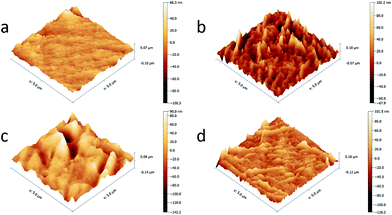 | ||
| Fig. 4 AFM images of (a) the PES substrate, (b) the PIP NF membrane, (c) the BDSA NF membrane and (d) the BDSA/PIP NF membrane. | ||
3.3 Hydrophilicity of the NF membranes
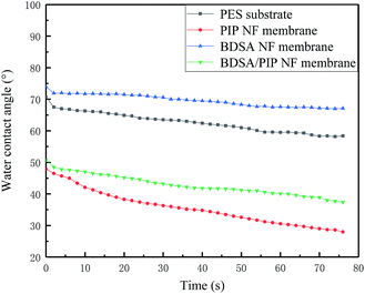
The hydrophilicity of the membranes has an important influence in membrane performance comprising antifouling property. Generally, the low contact angle (CA) emblematizes high hydrophilicity. The dynamic water contact angle (θ) of PES substrate and three TFC NF membranes was measured and shown in Fig. 5. The CA of the BDSA NF membrane was 67° which was higher than that of PES substrate (57°). It could be explained that the BDSA molecule possessed some rigidity due to the biphenyl unit, thus the sulfonic acid groups were covered by the polymer skeleton.16 The hydrophilicity of PIP NF membranes promoted obviously compared with PES substrate because the IP process introduced amide groups as well as unreacted carboxyl and amino on the top surface.7,25 The CA of the BDSA/PIP NF membrane (37°) was higher than that of the PIP NF membrane (28°) because of the existence of hydrophobic benzene rings in BDSA. Due to the interaction between PIP and BDSA, the hydrophilicity of the BDSA/PIP NF membrane improved remarkably compared with the BDSA NF membrane.3.4 Effect of preparation parameters on NF membrane performance
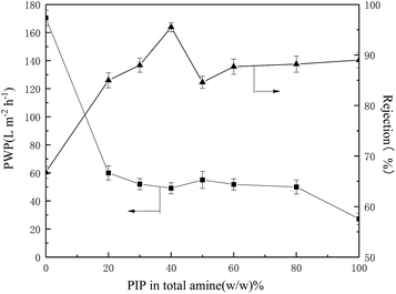
![[double bond, length as m-dash]](https://www.rsc.org/images/entities/char_e001.gif) O” percent increased comparing with the BDSA NF membrane. By mixing the rigid BDSA with PIP, the backbone stiffness and microporosity of the polyamide layer increased which resulted in the increment of permeability.21 With PIP ratio increased from 40% to 50%, the rejection reduced remarkably and permeability increased slightly. This could be ascribed to the competing effect between BDSA and PIP causing the decline of polymerization degree. With further increase of PIP/BDSA ratio, the rejection increased slowly while permeability decreased. The TFC membrane made in high PIP/BDSA ratio showed the characteristic of the PIP NF membrane.
O” percent increased comparing with the BDSA NF membrane. By mixing the rigid BDSA with PIP, the backbone stiffness and microporosity of the polyamide layer increased which resulted in the increment of permeability.21 With PIP ratio increased from 40% to 50%, the rejection reduced remarkably and permeability increased slightly. This could be ascribed to the competing effect between BDSA and PIP causing the decline of polymerization degree. With further increase of PIP/BDSA ratio, the rejection increased slowly while permeability decreased. The TFC membrane made in high PIP/BDSA ratio showed the characteristic of the PIP NF membrane.
3.5 Separation performance of the TFC NF membrane
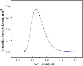
From the above discussion, the optimized preparation parameters could be obtained: 1% w/v amine (BDSA/PIP ratio 6/4) in aqueous solution, 0.12% TMC in organic solution and IP time 30 s. The separation performance of three TFC membranes (the PIP NF membrane, the BDSA NF membrane and the BDSA/PIP NF membrane fabricated under the optimized conditions) was further investigated.A series of neutral organic solutions (n-butyl alcohol, glucose, sucrose and raffinose, 300 ppm) were used to test the BDSA/PIP NF membrane in order to confirm the pore size and MWCO, and the rejection of organics was displayed in Table 3. The MWCO and pore radius of the TFC membrane were 394 Da and 0.52 nm respectively which were calculated by MATLAB. Fig. 9 was the pore size distribution curves.
| Solute | Molecular weight (Da) | Stokes radius (nm) | Solute rejection (%) |
|---|---|---|---|
| N-Butyl alcohol | 74 | 0.258 | 25 ± 1.0 |
| Glucose | 180 | 0.359 | 72.0 ± 1.2 |
| Sucrose | 342 | 0.462 | 88.2 ± 1.1 |
| Raffinose | 504 | 0.538 | 92.0 ± 1.3 |
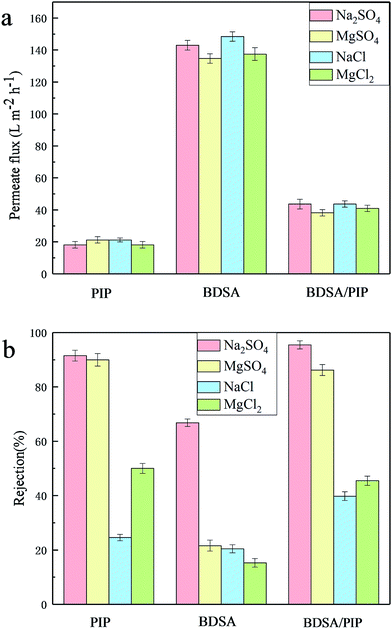
The TFC NF membranes were tested with four inorganic salt solutions (Na2SO4, MgSO4, MgCl2 and NaCl, 2000 ppm) to estimate the salt separating properties. The permeate flux and rejection of three TFC membranes to different salt solutions were exhibited in Fig. 10. The permeate flux of salt solutions was lower than PWP because of the concentration polarization.7 The permeate flux of the BDSA NF membrane was higher than the BDSA/PIP NF membrane and the PIP NF membrane. The sequence was consistent with the PWP in Fig. 8. The rejection of TFC membranes mainly followed the order: Na2SO4 > MgSO4 > MgCl2 > NaCl. The rejection to Na2SO4 and MgSO4 was higher than that of NaCl and MgCl2 because the anion with high valence was easier to be excluded by the negative surface than monovalent anion according to the Donnan exclusion.27 The rejection to Na2SO4 was higher than that of MgSO4. It was due to the combination between Mg2+ and the anions on the membrane surface, which would decrease the effective membrane surface charge, thus reducing the rejection performance. The rejection of the BDSA/PIP NF membrane and the PIP NF membrane was higher than the BDSA NF membrane owing to the higher cross-linking of the polyamide layer.
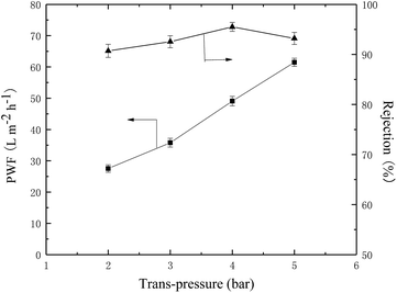
The permeation and rejection performance of TFC NF membrane under different pressures was shown in Fig. 11. It was obvious that the permeate flux increased linearly with pressure while the rejection to Na2SO4 fluctuated slightly. Therefore, the membrane showed the best performance under a pressure of 4 bar.
In addition, Table 4 listed the separating performance of various polyamide TFC membranes prepared with different monomers in aqueous phase in literatures and this work. By comparing these data, the BDSA/PIP NF membrane exhibited accredited flux as well as good rejection.
| Monomers | PWP (L m−2 h−1 bar−1) | Salt rejection (%) | Salt concentration (ppm) | Operation pressure (bar) | Reference | |||
|---|---|---|---|---|---|---|---|---|
| Na2SO4 | MgSO4 | MgCl2 | NaCl | |||||
| BHTTM + PIP | 5.2 | 99.7 | 94.0 | 28.0 | 45.0 | 2000 | 6 | 19 |
| PEI | 6.4 | — | — | 98.0 | 84.0 | 1000 | 10 | 28 |
| Amino-functional PEG | 13.2 | 45.8 | 80.2 | 95.4 | 54.8 | 2000 | 5 | 3 |
| PEI + PIP | 5.1 | 50.0 | 74.0 | 92.0 | 65.0 | 500 | 8 | 29 |
| BDSA + PIP | 12.3 | 95.5 | 86.2 | 45.5 | 39.8 | 2000 | 4 | This work |
3.6 Antifouling properties of the TFC NF membranes over long-term running
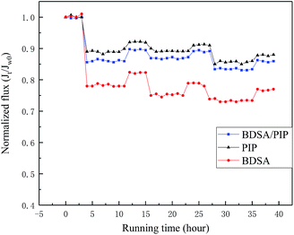
A long-term testing consisted of three cycles was carried out to evaluate the antifouling performance of three TFC NF membranes. The permeability was measured every hour and the normalized flux (Jt/Jw0) was illustrated in Fig. 12. The permeate flux declined notably when the feed solution changed to 0.3 g L−1 BSA in the first cycle and recovered to a certain degree after washed with DI water, while in the following testing, the TFC membrane showed a negligible decline in permeability. The Rr, Rir, FDR and FRR of the three membranes after three-cycles test were exhibited in Table 5. The BDSA/PIP NF membrane showed unfavourable performance in the fouling test while both the PIP NF membrane and the BDSA/PIP NF membrane expressed good antifouling performance. The antifouling performance of the TFC NF membranes was consistent with the water contact angle in Fig. 5. The hydrophilic membrane surface could build up a thin water layer to prevent the BSA deposition and adsorption.17 Furthermore, the pollutant was difficult to adsorb and accumulate in the smooth surface of the BDSA/PIP NF membrane. The result indicated good antifouling properties and application prospect of the BDSA/PIP NF membrane over long-term running.| Membrane | FRR (%) | FDR (%) | Rr (%) | Rir (%) |
|---|---|---|---|---|
| PIP | 87.8 | 14.4 | 2.2 | 12.2 |
| BDSA | 76.8 | 26.7 | 3.5 | 23.2 |
| BDSA/PIP | 85.7 | 16.7 | 2.4 | 14.3 |
4. Conclusions
A TFC hollow fiber NF membrane with high performance and good antifouling properties was fabricated with BDSA and PIP as mixed amine monomers in aqueous phase. The membrane preparation parameters including TMC concentration, reaction time and BDSA/PIP ratio were investigated and the optimized NF membrane showed a PWP of 49.1 L m−2 h−1 and Na2SO4 rejection of 95.5%. The result of XPS, SEM and AFM showed that the BDSA/PIP NF membrane hold a denser and smoother surface than TFC membranes prepared with simplex monomer in aqueous phase. The rejection to different inorganic salts conformed to the following sequence: Na2SO4 > MgSO4 > MgCl2 > NaCl. The MWCO and pore radius of the TFC membrane were about 400 Da and 0.52 nm which were calculated by MATLAB simulation according to the rejection of neutral organics. A fouling test of 0.3 g L−1 BSA solution was carried out to investigate the antifouling properties of the TFC membrane, the FDR and FRR after long-term running were 16.7% and 85.7%, respectively. The good separation performance and fouling resistance indicated comprehensive application potential of the TFC hollow fiber NF membrane.Conflicts of interest
There are no conflicts to declare.Acknowledgements
We acknowledge the financial support received from the National Science and Technology Support Project of China (2014BAB07B01 and 2015BAB09B01) and the Key Technology R&D Program of Jiangsu Committee of Science and Technology in China (BE2013031).References
- P. Mou and S. D. Jons, Polymer, 2016, 103, 417–456 CrossRef.
- Y. Pan, R. Xu, Z. Lü, S. Yu, M. Liu and C. Gao, J. Membr. Sci., 2017, 523, 282–290 CrossRef CAS.
- X. Q. Cheng, L. Shao and C. H. Lau, J. Membr. Sci., 2015, 476, 95–104 CrossRef CAS.
- Y. J. Tang, Z. L. Xu, S. M. Xue, Y. M. Wei and Y. Hu, J. Membr. Sci., 2016, 498, 374–384 CrossRef CAS.
- Y.-J. Tang, L.-J. Wang, Z.-L. Xu, Y.-M. Wei and H. Yang, J. Membr. Sci., 2016, 502, 106–115 CrossRef CAS.
- D. Rana and T. Matsuura, Chem. Rev., 2010, 110, 2448–2471 CrossRef CAS PubMed.
- A. Akbari, E. Aliyarizadeh, S. M. Mojallali Rostami and M. Homayoonfal, Desalination, 2016, 377, 11–22 CrossRef CAS.
- W. Li, C. Bian, C. Fu, A. Zhou, C. Shi and J. Zhang, J. Membr. Sci., 2016, 504, 185–195 CrossRef CAS.
- Q. An, F. Li, Y. Ji and H. Chen, J. Membr. Sci., 2011, 367, 158–165 CrossRef CAS.
- Y. T. Chung, E. Mahmoudi, A. W. Mohammad, A. Benamor, D. Johnson and N. Hilal, Desalination, 2017, 402, 123–132 CrossRef CAS.
- J. Zheng, M. Li, K. Yu, J. Hu, X. Zhang and L. Wang, J. Membr. Sci., 2017, 524, 344–353 CrossRef CAS.
- M. Yang, C. Zhao, S. Zhang, P. Li and D. Hou, Appl. Surf. Sci., 2017, 394, 149–159 CrossRef CAS.
- S. M. Xue, Z. L. Xu, Y. J. Tang and C. H. Ji, ACS Appl. Mater. Interfaces, 2016, 8, 19135–19144 CAS.
- Z. Geng, X. Yang, C. Boo, S. Zhu, Y. Lu, W. Fan, M. Huo, M. Elimelech and X. Yang, J. Membr. Sci., 2017, 529, 1–10 CrossRef CAS.
- J. Zhu, L. Qin, A. Uliana, J. Hou, J. Wang, Y. Zhang, X. Li, S. Yuan, J. Li, M. Tian, J. Lin and B. Van der Bruggen, ACS Appl. Mater. Interfaces, 2017, 9, 1975–1986 CAS.
- M. Li, Y. Yao, W. Zhang, J. Zheng, X. Zhang and L. Wang, Environ. Sci. Technol., 2017, 51, 9253–9260 Search PubMed.
- Z. Lv, J. Hu, J. Zheng, X. Zhang and L. Wang, Ind. Eng. Chem. Res., 2016, 55, 4726–4733 CrossRef CAS.
- X. Weng, Y. Ji, F. Zhao, Q. An and C. Gao, RSC Adv., 2015, 5, 98730–98739 RSC.
- B.-W. Zhou, H.-Z. Zhang, Z.-L. Xu and Y.-J. Tang, Desalination, 2016, 394, 176–184 CrossRef CAS.
- J. Hu, Z. Lv, Y. Xu, X. Zhang and L. Wang, J. Membr. Sci., 2016, 505, 119–129 CrossRef CAS.
- Y.-J. Tang, Z.-L. Xu, S.-M. Xue, Y.-M. Wei and H. Yang, J. Membr. Sci., 2017, 541, 483–491 CrossRef CAS.
- J. Gao, S.-P. Sun, W.-P. Zhu and T.-S. Chung, J. Membr. Sci., 2016, 499, 361–369 CrossRef CAS.
- H.-Z. Zhang, Z.-L. Xu, Y.-J. Tang and H. Ding, J. Membr. Sci., 2017, 527, 111–120 CrossRef CAS.
- Y.-J. Tang, Z.-L. Xu, B.-Q. Huang, Y.-M. Wei and H. Yang, RSC Adv., 2016, 6, 45585–45594 RSC.
- H.-Z. Zhang, Z.-L. Xu, H. Ding and Y.-J. Tang, Desalination, 2017, 420, 158–166 CrossRef CAS.
- X. Li, Y. Cao, H. Yu, G. Kang, X. Jie, Z. Liu and Q. Yuan, J. Membr. Sci., 2014, 466, 82–91 CrossRef CAS.
- H. Tang, J. He, L. Hao, F. Wang, H. Zhang and Y. Guo, J. Membr. Sci., 2017, 524, 612–622 CrossRef CAS.
- Z. Thong, Y. Cui, Y. K. Ong and T.-S. Chung, ACS Sustainable Chem. Eng., 2016, 4, 5570–5577 CrossRef CAS.
- D. Wu, S. Yu, D. Lawless and X. Feng, React. Funct. Polym., 2015, 86, 168–183 CrossRef CAS.
| This journal is © The Royal Society of Chemistry 2017 |

