 Open Access Article
Creative Commons Attribution 3.0 Unported Licence
Air electrode based on poly(3,4-ethylenedioxythiophene) microflower/graphene composite for superior Li–O2 batteries with excellent cycle performance†
S. H. Yoon and
Y. J. Park *
*
Department of Advanced Materials Engineering, Kyonggi University, 154-42, Gwanggyosan-Ro, Yeongtong-Gu, Suwon-Si, Gyeonggi-Do 443-760, Republic of Korea. E-mail: yjpark2006@kyonggi.ac.kr
First published on 15th December 2017
Abstract
We report the use of poly(3,4-ethylenedioxythiophene) (PEDOT) microflowers as a potential electrode material for Li–O2 batteries. PEDOT is a conducting polymer that shows catalytic activity for the formation and dissociation of Li2O2 in Li–O2 cells. The microflower morphology composed of intertwined nanofibers is expected to increase the number of active sites for the redox reaction during the discharging-charging process. Although the electronic conductivity of the PEDOT microflowers is not so low, it is insufficient to achieve a large capacity for the electrode material in Li–O2 cells. Thus, a composite was prepared using 5–20 wt% of graphene as the matrix to compensate for the low conductivity of the PEDOT microflowers. The electrode employing the PEDOT microflower/graphene composite presents much higher capacity than that of the electrode employing pristine PEDOT microflowers, because of the enhanced electronic conductivity. Moreover, the electrode shows enhanced cycle performance compared to that of the electrode employing pristine graphene. This is because the microflower surface can suppress the side reactions activated by carbon, thereby reducing the accumulation of unwanted reaction products on the electrode.
Introduction
Lithium ion batteries (LIBs), which are based on the principle of intercalation chemistry, constitute an important energy-storage technology and find widespread application in portable electronics. In particular, LIBs have enabled the transition of transportation power systems from combustion engines to electric motors. This transition is just an initial stage, but rapidly underway with an incursion of electric vehicles into the marketplace. However, the current battery chemistry based on intercalation cannot satisfy the requirements for energy-storage density in electric vehicles with sufficient travelling distance (after a single charging process). Hence, much effort has been devoted to surpassing the limitations of existing LIBs.1–7 Li–O2 batteries (also called Li–air batteries) based on new battery chemistry, metal-molecule electrochemical redox couples, have received significant interest owing to their remarkably high energy density.8–15 However, the practical application of these batteries is limited by their inherent drawbacks such as high overpotential, low energy efficiency, and short cycle life, which are related to the basic reaction between the oxygen and lithium ions.8–15 A typical non-aqueous Li–O2 cell consists of an air electrode (cathode), organic electrolyte, and lithium anode. Upon discharging, molecular oxygen is reduced to superoxide, which combines with lithium ions at the air electrode, to form insoluble products (ideally Li2O2).16–25 The air electrodes act as the host matrix for the redox reactions and as storage sites for the reaction products; hence, the electrochemical performance of Li–O2 cells is strongly dependent on the property of air electrodes. Upon charging, the previously formed reaction products should be completely dissociated so that reversible long cycling is achieved. However, in reality, the residual products gradually accumulate on the air electrode, clogging the pores on the electrode, and hindering the electrode reaction. This results in suffocation of the Li–O2 cells, and consequently, poor cycle performance and high overpotential during cycling.26–33 Note that most of these residual products are not Li2O2 but undesired products such as Li2CO3 and organics originating from the side reaction in the Li–O2 cells. Li2O2 can react with carbon in the air electrode at the Li2O2/carbon interphase to form Li2CO3. The electrolyte can decompose at high voltages too furnish organics such as CH3CO2Li and HCO2Li.34–38 These unwanted products hardly dissociate even when the cell is charged at a high potential and easily accumulate on the air electrode surface. Unfortunately, these side reactions are inevitable as they are activated by carbon materials, which are commonly used for the matrix in air electrodes because of their high specific area, high electronic conductivity, and low cost.In previous work, film-type poly(3,4-ethylenedioxythiophene) polystyrene sulfonate (PEDOT:PSS), a conducting polymer, has been proposed as a candidate material for air electrodes.39,40 Such conducting polymers can be a suitable replacement to carbon owing to their good electronic conductivity, light weight, high catalytic activity, and high stability under oxygen reduction and evolution conditions. However, film-type PEDOT:PSS cannot provide a sufficiently large surface area for the redox reaction. In the present study, poly(3,4-ethylenedioxythiophene) (PEDOT) microflowers composited with a small amount of graphene (5–20 wt%) was prepared for use as the base material for a superior air electrode. The microflower-like PEDOT particles offer a larger surface area as compared to the film-type PEDOT layer. The PEDOT microflower/graphene composite is expected to serve as an effective site for the redox reaction for between the oxygen and lithium ions, in addition to offering storage space for the reaction products. Moreover, the use of this composite helps in suppressing undesired side reactions as the electrode surface predominantly comprises the PEDOT layer, and not carbon. Consequently, a superior air electrode with better cyclic performance as compared that of carbon-based electrodes can be realised.
Experimental
Synthesis of PEDOT microflowers and PEDOT microflower/graphene composites
First, a ternary solution was prepared, composed of surfactant sodium bis(2-ethylhexyl) sulfosuccinate (AOT, Aldrich, 96%), 7 M aqueous solution of FeCl3 (Aldrich, 97%), and p-xylene (Aldrich, anhydrous, ≥99%). The molar ratio (N) of water (used to dissolve FeCl3) to the surfactant was adjusted to 30.41,42 The surfactant AOT was dissolved in 20 mL p-xylene in a beaker to obtain a concentration of 1.5 M. Then the AOT/p-xylene solution was stirred for 20 min and diffused via ultrasonic treatment for 20 min. The 7 M aqueous FeCl3 solution was added to the above mixture with constant stirring. Then a 3,4-ethylenedioxythiophene monomer (EDOT, Aldrich, 97%) was slowly dripped into the stirred solution to prepare PEDOT microflower. To prepare the PEDOT microflower/graphene composites, different amounts of commercial graphene (Graphene Supermarket Co., AO-1) was immersed in the AOT solution (5, 10, 20 wt% of PEDOT microflower) before adding the EDOT monomer. This solution was reacted continuously for 24 h at room temperature. The reacted final solution was then isolated by centrifugation and was washed with ethanol and a water–ethanol mixture (1![[thin space (1/6-em)]](https://www.rsc.org/images/entities/char_2009.gif) :
:![[thin space (1/6-em)]](https://www.rsc.org/images/entities/char_2009.gif) 1 v/v) several times to remove residual materials until the supernatant was colourless and transparent. Finally, the residual product dried under vacuum at 80 °C for 24 h.
1 v/v) several times to remove residual materials until the supernatant was colourless and transparent. Finally, the residual product dried under vacuum at 80 °C for 24 h.
Electrochemical tests
The electrodes employing pristine PEDOT microflower (without graphene) and PEDOT microflower/graphene composites were composed of 100% sample powder (without binder). However, the pristine graphene electrode was prepared by mixing 90 wt% pristine graphene with 10 wt% PVDF binder. The loading weight of the electrodes was adjusted to 0.3 mg ± 0.03 mg. The electrochemical performance of the electrodes was studied using a modified Swagelok cell consisting of an air electrode, a metallic Li anode, a glass filter (Whatman) separator, and an electrolyte containing 0.5 M LiTFSI and 0.5 M LiNO3 in tetraethylene glycol dimethyl ether (TEGDME). The cells were assembled in an Ar-filled glove box and were subjected to galvanostatic cycling using a WonATech battery cycler (WBCs 3000). A potential range of 2.0–4.35 V (vs. Li/Li+) and various current densities (20, 100, 200, and 400 mA gelectrode−1) were used for the electrochemical test. All experiments were conducted under an O2 atmosphere under ambient pressure.Characterization of the electrode materials
Transmission electron microscopy (TEM, JEM-2100F (HR)) and scanning electron microscopy (SEM, Nova NanoSEM 450, FEI Co.) were employed to observe the shape of the PEDOT microflower and the PEDOT microflower/graphene composites. In addition, Fourier-transform infrared spectroscopy (FTIR, Nicolet 5700, Thermo Electron Corp.) was performed to examine the formation of samples. 4-Point probe system (CMT-SR2000N, Advanced Instrument Technology) was also used to measure the resistivity of the plat electrode composed of PEDOT microflowers or PEDOT microflower/graphene composites. Furthermore, the surface morphologies of the air electrodes before and after cycling were observed using the above-mentioned SEM and FTIR techniques. To prepare the cycled specimens for SEM and FTIR, the air electrodes were collected after 50 cycles and washed several times with dimethyl carbonate (DMC), and then stored in vacuum chamber for 24 h. The specimens were packed in vacuum before being transferred to the instruments.Results and discussion
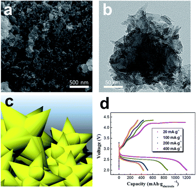
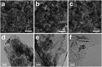
SEM and TEM images (Fig. 1a and b) revealed that the pristine PEDOT microflowers (prior to composite formation with graphene) were composed of intertwined nanofibers. The surface of the particles had thorn-like protrusions, as illustrated in Fig. 1c, which provided a large surface area for the storage of reaction products during the cycling of the Li–O2 cell. Moreover, each cluster had numerous pores that may allow access to the electrolyte containing Li ions and dissolved oxygen. The size of each PEDOT microflower cluster was 200–500 nm. To determine the electrochemical performance of pristine PEDOT microflower, the discharge–charge capacity of the Li–O2 cell employing these microflowers was measured (Fig. 1d). The discharge–charge process proceeded normally, which is meaningful because the pure carbon-free conducting polymer acts as the electrode material (cathode) for the Li–O2 cell. This also indicates that PEDOT microflower shows catalytic activity for the redox reactions between Li ions and oxygen. The capacity reached ∼1200 mA h gelectrode−1 at a low current density (20 mA gelectrode−1) but decreased significantly with an increase in the current density. This rapid capacity reduction at high current density may be attributed to the lower electronic conductivity of the PEDOT microflower as compared to the carbon-based electrodes. To compensate for the low conductivity, the pristine PEDOT microflowers were composited with graphene, which has high conductivity.Fig. 2 presents SEM and TEM images of the PEDOT microflower/graphene composites, in which the weight ratio of graphene was controlled to 5, 10, and 20 wt%. As seen in the SEM images (Fig. 2a–c), the PEDOT microflower clusters seemed to adhere to the surface of the graphene matrix. It is believed that PEDOT with slight adhesion to the graphene surface with large specific surface area is easily complexed. The surface of the composite containing 5 wt% graphene was mostly covered with PEDOT microflowers. However, when the graphene content was increased to 10 and 20 wt%, the graphene bare surface without the PEDOT microflowers was revealed. Fig. 2d–f show the TEM images of the composites containing 5, 10, and 20 wt% graphene. The PEDOT microflowers were stably attached to the graphene surface, indicating the successful formation of the composite. The surface coverage by the PEDOT microflowers clearly decreased with increasing graphene ratio. The surface of the PEDOT microflower/graphene composite acts as the reaction site and provides storage space for the reaction products during the operation of the constituent Li–O2 cell. The graphene surface covered with the microflowers showed good catalytic activity for the redox reaction between Li ions and oxygen, but the bare-graphene (carbon) surface triggered unwanted side reactions such as the formation of Li2CO3 and decomposition of the electrolyte.34–38 The surface of the PEDOT microflower showed considerable electronic conductivity and catalytic activity, as shown in Fig. 1d. Thus, composite with the PEDOT microflower surface and graphene matrix may be a promising electrode material for Li–O2 cells.
Fig. 3 shows the Fourier transform infrared (FTIR) spectra of the pristine PEDOT microflower and PEDOT microflower/graphene composites. As the content of graphene increased, the intensity of the absorbance peaks associated with PEDOT decreased because of low amount of PEDOT. However, peaks position of the composites was almost similar to those of the pristine PEDOT microflowers, which indicated that the PEDOT structure was unchanged during composite formation.
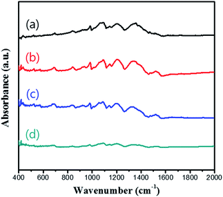 | ||
| Fig. 3 FTIR spectra of (a) pristine PEDOT microflowers and PEDOT microflower/graphene composites containing (b) 5 wt%, (c) 10 wt%, and (d) 20 wt% graphene. | ||
The electrochemical properties of the electrode employing the PEDOT microflower/graphene composites were observed to determine the effects of the graphene matrix. For comparison, the electrode employing pristine graphene was also prepared. Hereafter, the electrode employing the pristine graphene will be referred to as the ‘graphene electrode’, and the electrode employing the PEDOT microflower/graphene composites containing 5, 10, and 20 wt% graphene will be referred to as ‘comp-5’, ‘comp-10’, and ‘comp-20’ electrodes, respectively.
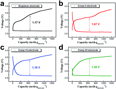
Fig. 4 shows the initial discharge–charge profiles of the cell employing the four different electrodes at a current density of 400 mA gelectrode−1, with the capacity limited to 1500 mA h gelectrode−1. All the electrodes presented stable discharge–charge profiles with a capacity of 1500 mA h gelectrode−1. Considering that the capacity of the electrode employing pristine PEDOT microflowers was only ∼430 mA h gelectrode−1 at 400 mA gelectrode−1 (Fig. 1d), the introduction of graphene dramatically increased the capacity of the electrode, which could be attributed to the enhanced electronic conductivity. For comparison of electronic conductivities, flat electrodes were prepared using graphene, pristine PEDOT microflowers, and composites with 5, 10, and 20 wt% graphene. The resistivity of the flat graphene electrode was just ∼0.41 Ω cm, while that of the flat electrode fabricated using the pristine PEDOT microflowers was ∼2.9 Ω cm. However, the resistivities of the flat electrodes fabricated from the composites containing 5, 10, and 20 wt% graphene decreased to ∼1.5, 1.1, and 0.9 Ω cm, respectively.
The average overpotentials of four electrodes were 1.07–1.26 V. Interestingly, the comp-5 electrode showed a smaller overpotential than those of the graphene and comp-20 electrodes having high electronic conductivity. This may imply that catalytic activity of the PEDOT microflowers is comparable to that of graphene. The over-potential of the Li–O2 cell is strongly associated with the dissociation of reaction products during charging, indicating that the PEDOT microflowers act a better catalyst for the dissociation of Li2O2 than does pristine graphene.
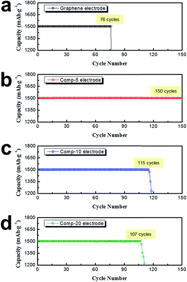
The cycling performance of the Li–O2 cells employing the graphene as well as the comp-5, comp-10, and comp-20 electrodes was then evaluated at a current density of 400 mA gelectrode−1. The cell capacity was set at 1500 mA h gelectrode−1 to minimize the depth of discharge.43 As shown in Fig. 5a, the cycle life of the graphene electrode was only 76 cycles under these measurement conditions. In contrast, the electrode employing the PEDOT microflower/graphene composites presented much superior cyclic performance, and especially, the comp-5 electrode maintained a constant capacity (1500 mA h gelectrode−1) over 150 cycles. However, as the increase of the amount of graphene, the cycle life was somewhat reduced. Fig. S1† shows the variation in the discharge–charge profiles of the four electrodes during cycling.
The cycle lives of the non-aqueous Li–O2 cells are associated with several factors such as the accumulation of reaction products on the air electrode (cathode), electrolyte loss by evaporation and unwanted side reactions, and unstable Li anode.1,8,9,21 The instability of the Li anode and evaporation of the electrolyte cannot be controlled under our experimental conditions. Thus, the cyclic performance of our electrodes is highly dependent on side reactions such as the formation of Li2CO3 at the Li2O2/carbon interface and decomposition of the electrolyte during cycling. The side reactions yield unwanted products such as Li2CO3 and organic materials (e.g., CH3CO2Li and HCO2Li), which are not dissociated during charging but accumulate on the surface of the electrode. Moreover, decomposition of the electrolyte by side reactions leads to electrolyte loss. Accordingly, the superior cyclic performance of the electrode employing PEDOT microflower/graphene composites may imply that the microflowers on the electrode surface can suppress unwanted side reactions.
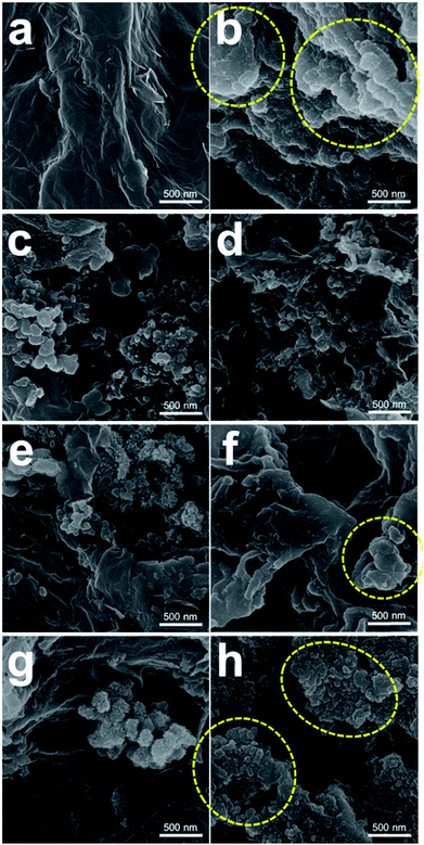
To evaluate the effect of the PEDOT microflowers on the surface of composite, the graphene, comp-5, 10 and 20 electrodes were analysed using SEM and FTIR spectroscopy. Fig. 6 presents the SEM images of the graphene, comp-5, 10, 20 electrodes before and after 50 cycles (charged state) at 400 mA gelectrode−1 with a limited capacity of 1500 mA h gelectrode−1. The surface morphology of the electrodes before the cycles (Fig. 6a, c, e and g) was similar to that of the powder samples shown in Fig. 2. Fig. S2† shows the SEM images of the electrodes after the initial discharge. The surface of the electrodes seemed to be covered by a film composed of the reaction products. As shown in Fig. S1a and S1b,† the graphene surface was still smooth, implying that the reaction products were homogeneously attached to the surface of the graphene electrode. In contrast, the surface of the graphene electrode after 50 cycles displayed thick and cluster-type reaction products, as indicated by the yellow circles in Fig. 6b. Ideally, when the electrode is charged state, most of the reaction products are expected to dissociate from its surface. However, a considerable amount of reaction products was accumulated on the graphene electrode, because of the insufficient cycle life (Fig. 5a). On the contrary, no such reaction products were seen on the surface of the comp-5 electrode even after 50 cycles (Fig. 6d). While we cannot exclude the possibility that reaction products could have accumulated on the surface of the PEDOT microflower electrode, large heterogeneous reaction products observed with the graphene electrode were not seen in the present case. In contrast, some cluster-type reaction products appeared on the surface of the comp-20 electrode after 50 cycles (yellow circles in Fig. 6h) because of the predominant graphene content.
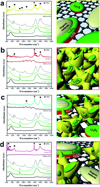
The FTIR spectra of the four electrodes after 50 cycles (charged state) were also analysed to identify the presence of residual reaction products during cycling. As shown in the left column of Fig. 7a, several absorbance peaks were observed in the spectrum of the graphene electrode (after 50 cycles) in the 400–700 and 1350–1700 cm−1 (marked with ★) region. These peaks are attributable to unwanted products such as CH3CO2Li and Li2CO3, which presenting that the most of the residual reaction products are attributed to the accumulation of unwanted reaction products derived from side reactions. The right column of Fig. 7a illustrates the formation of unwanted reaction products on the surface of the graphene electrode. The FTIR spectrum of the comp-5 electrode after 50 cycles also contained peaks due to these products, the peak intensities were significantly lower than those for the graphene electrode (left column of Fig. 7b). This result indicates that the PEDOT microflower layer effectively reduces the accumulation of unwanted reaction products on the electrode surface. As illustrated in the right column of Fig. 7b, the PEDOT microflower covering the graphene matrix prevents direct contact between carbon and Li2O2 and/or the electrolyte, thus suppressing the side reactions at the carbon/Li2O2 and carbon/electrolyte interfaces. This in turn reduces the formation of residual reaction products and leads to enhanced cyclic performance, as shown in Fig. 5b. However, in the spectra of the comp-20 electrode after 50 cycles, the intensity of the peaks related to the unwanted reaction products increased compared to that for the comp-5 electrode (left column of Fig. 7d), implying that the amount of residual products increased with the graphene content.
This result could be explained by the area of the surface covered with microflowers in the PEDOT microflower/graphene composite. As shown in Fig. 2, most of the surface of the comp-5 electrode was protected from the reactive Li2O2 and electrolyte by the PEDOT microflower clusters. However, a considerable portion of the surface of the comp-20 electrode was graphene (carbon), so the exposed carbon surface activated side reactions, resulting in the accumulation of unwanted products on the electrode, as illustrated in the right column of the Fig. 7d. This could explain the inferior cyclic performance of the comp-20 electrode compared to that of the comp-5 or 10 electrodes (Fig. 5). Thus, the electrode surface covered with PEDOT microflowers would be preferable for obtaining Li–O2 cells with excellent cycle performance.
Conclusions
In this article, PEDOT microflowers are introduced as a potential electrode material for Li–O2 batteries. The electrodes with pristine PEDOT microflowers showed stable discharge–charge profiles in the Li–O2 cells, but their capacity was very small due to the low electronic conductivity. In contrast, the composite composed of the graphene matrix covered with PEDOT microflowers presented notable capacity and low overpotential. The cycle performance of the electrodes employing the PEDOT microflower/graphene composite was superior to that of the electrode employing pristine graphene.Specially, PEDOT microflower/graphene composite containing 5 wt% graphene was the most suitable for the material of air electrodes, within our experimental conditions. As a reference, the comparison of the cyclic performance of the Li–O2 cells containing carbon-based composites was summarized in the Table 1. As per SEM and FTIR analysis, the residual reaction products derived from side reactions were decreased due to the coverage of the electrode surface by the PEDOT microflowers. As illustrated in Fig. 8, unwanted reaction products are easily accumulated on the surface of graphene because the carbon surface activates the side reactions. However, the surface of the PEDOT microflowers can suppress such side reaction and reduce the formation of residual reaction products on the electrode, leading to enhanced cycle performance. In this context, the composite in which a large portion of the graphene surface was exposed inferior cycle performance as compared to that whose surface mostly covered by PEDOT microflowers.
| Component | Limited capacity [mA h g−1] | Cycle life [cycles] | Reference |
|---|---|---|---|
| PEDOT microflower/graphene composites | 1500 | 150 | This study |
| PEDOT:PSS coated graphene | 1000 | 100 | 39 |
| Polydopamine-assisted carbon nanotubes/Co3O4 composites | 1000 | 16 | 10 |
| Carbon-sphere/Co3O4 nanocomposites | 1000 | 19 | 25 |
| Co3O4 nanofiber/non-oxidized graphene nanoflake | 1000 | 80 | 5 |
| In situ-grown ZnCo2O4 on single-walled CNTs | 1500–2750 | 10 | 8 |
| Pre-lithiation of NiCo2O4 nanowires/carbon fabric | 1000–1500 | ∼120 | 16 |
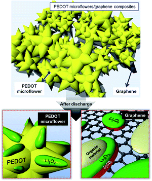 | ||
| Fig. 8 Schematic illustrations of the reactions taking place on the PEDOT microflower surface and graphene surface. | ||
Conflicts of interest
There are no conflicts to declare.Acknowledgements
This research was supported by the Basic Science Research Program through the National Research Foundation of Korea (NRF), funded by the Ministry of Science, ICT, and Future Planning (NRF-2014R1A2A2A01003542 and NRF-2017R1A2B4006105), and by the Korea Ministry of Environment as Advanced Technology Program for Environmental Industry (No. 2016000140004).Notes and references
- A. C. Luntz and B. D. McCloskey, Chem. Rev., 2014, 114, 11721–11750 CrossRef CAS PubMed.
- Z. Peng, S. A. Freunberger, Y. H. Chen and P. G. Bruce, Science, 2012, 337, 563–566 CrossRef CAS PubMed.
- J. Lu, Y. J. Lee, X. Luo, K. C. Lau, M. Asadi, H.-H. Wang, S. Brombosz, J. Wen, D. Zhai, Z. Chen, D. J. Miller, Y. S. Jeong, J.-B. Park, Z. Z. Fang, B. Kumar, A. Salehi-Khojin, Y.-K. Sun, L. A. Curtiss and K. Amine, Nature, 2016, 529, 377–382 CrossRef CAS PubMed.
- J.-S. Lee, S. T. Kim, R. Cao, N.-S. Choi, M. Liu, K. T. Lee and J. Cho, Adv. Energy Mater., 2011, 1, 34–50 CrossRef CAS.
- W.-H. Ryu, T.-H. Yoon, S. H. Song, S. Jeon, Y.-J. Park and I.-D. Kim, Nano Lett., 2013, 13, 4190–4197 CrossRef CAS PubMed.
- X. Gao, Y. Chen, L. Johnson and P. G. Bruce, Nat. Mater., 2016, 15, 882–888 CrossRef CAS PubMed.
- H.-D. Lim, B. Lee, Y. Zheng, J. Hong, J. Kim, H. Gwon, Y. Ko, M. Lee, K. Cho and K. Kang, Nat. Energy, 2016, 1, 16066 CrossRef CAS.
- B. Liu, W. Xu, P. Yan, P. Bhattacharya, R. Cao, M. E. Bowden, M. H. Engelhard, C.-M. Wang and J.-G. Zhang, ChemSusChem, 2015, 8, 3697–3703 CrossRef CAS PubMed.
- A. Kraytsberg and Y. Ein-Eli, J. Power Sources, 2011, 196, 886–893 CAS.
- T. H. Yoon and Y. J. Park, J. Power Sources, 2013, 244, 344–353 CAS.
- B. M. Gallant, D. G. Kwabi, R. R. Mitchell, J. Zhou, C. V. Thompson and Y. Shao-Horn, Energy Environ. Sci., 2013, 6, 2518–2528 CAS.
- Y. G. Zhu, C. Jia, J. Yang, F. Pan, Q. Huang and Q. Wang, Chem. Commun., 2015, 51, 9451–9454 RSC.
- H. Kim, H.-D. Lim, J. Kim and K. Kang, J. Mater. Chem. A, 2014, 2, 33–47 CAS.
- K. R. Yoon, D. S. Kim, W.-H. Ryu, S. H. Song, D.-Y. Youn, J.-W. Jung, S. Jeon, Y. J. Park and I.-D. Kim, ChemSusChem, 2016, 9, 2080–2088 CrossRef CAS PubMed.
- F. Li, T. Zhang and H. Zhou, Energy Environ. Sci., 2013, 6, 1125–1141 CAS.
- B. Liu, P. Yan, W. Xu, J. Zheng, Y. He, L. Luo, M. E. Bowden, C.-M. Wang and J.-G. Zhang, Nano Lett., 2016, 16, 4932–4939 CrossRef CAS PubMed.
- P. G. Bruce, S. A. Freunberger, L. J. Hardwick and J.-M. Tarascon, Nat. Mater., 2012, 11, 19–29 CrossRef CAS PubMed.
- T.-H. Yoon and Y. J. Park, RSC Adv., 2014, 4, 17434–17442 RSC.
- R. Padbury and X. Zhang, J. Power Sources, 2011, 196, 4436–4444 CrossRef CAS.
- D. S. Kim and Y. J. Park, Electrochim. Acta, 2014, 132, 297–306 CrossRef CAS.
- J. Christensena, P. Albertusa, R. S. Sanchez-Carrerab, T. Lohmanna, B. Kozinskyb, R. Liedtkec, J. Ahmeda and A. Kojica, J. Electrochem. Soc., 2012, 159, R1–R30 CrossRef.
- Z. W. Chang, J.-J. Xu, Q.-C. Liu, L. Li and X.-B. Zhang, Adv. Energy Mater., 2015, 5, 1500633 CrossRef.
- C. K. Lee and Y. J. Park, ACS Appl. Mater. Interfaces, 2016, 8, 8561–8567 CAS.
- F. Cheng and J. Chen, Chem. Soc. Rev., 2012, 41, 2172–2192 RSC.
- C. S. Park, K. S. Kim and Y. J. Park, J. Power Sources, 2013, 244, 72–79 CrossRef CAS.
- B. D. Adams, C. Radtke, R. Black, M. L. Trudeau, K. Zaghib and L. F. Nazar, Energy Environ. Sci., 2013, 6, 1772–1778 CAS.
- Y.-C. Lu and Y. Shao-Horn, J. Phys. Chem. Lett., 2013, 4, 93–99 CrossRef CAS PubMed.
- D. S. Kim and Y. J. Park, J. Alloys Compd., 2014, 591, 164–169 CrossRef CAS.
- Y. Cui, Z. Wen and Y. Liu, Energy Environ. Sci., 2011, 4, 4727–4734 CAS.
- H.-D. Lim, K.-Y. Park, H. Song, E. Y. Jang, H. Gwon, J. Kim, Y. H. Kim, M. D. Lima, R. O. Robles, X. Lepró, R. H. Baughman and K. Kang, Adv. Mater., 2013, 25, 1348–1352 CrossRef CAS PubMed.
- W.-J. Kwak, D. Hirshberg, D. Sharon, M. Afri, M. M. Frimer, H.-G. Jung, D. Aurbach and Y.-K. Sun, Energy Environ. Sci., 2016, 9, 2334–2345 CAS.
- D. H. Yoon and Y. J. Park, J. Electroceram., 2014, 33, 155–162 CrossRef CAS.
- G. Girishkumar, B. McCloskey, A. C. Luntz, S. Swanson and W. Wilcke, J. Phys. Chem. Lett., 2010, 1, 2193–2203 CrossRef CAS.
- J. Lu, Y. Lei, K. C. Lau, X. Luo, P. Du, J. Wen, R. S. Assary, U. Das, D. J. Miller, J. W. Elam, H. M. Albishri, D. A. El-Hady, Y.-K. Sun, L. A. Curtiss and K. Amine, Nat. Commun., 2013, 4, 2383 Search PubMed.
- B. D. McCloskey, A. Speidel, R. Scheffler, D. C. Miller, V. Viswanathan, J. S. Hummelshøj, J. K. Nørskov and A. C. Luntz, J. Phys. Chem. Lett., 2012, 3, 997–1001 CrossRef CAS PubMed.
- C. K. Lee and Y. J. Park, Chem. Commun., 2015, 51, 1210–1213 RSC.
- M. M. Ottakam Thotiyl, S. A. Freunberger, Z. Peng and P. G. Bruce, J. Am. Chem. Soc., 2013, 135, 494–500 CrossRef CAS PubMed.
- M. M. Ottakam Thotiyl, S. A. Freunberger, Z. Peng, Y. Chen, Z. Liu and P. G. Bruce, Nat. Mater., 2013, 12, 1050–1056 CrossRef CAS PubMed.
- D. H. Yoon, S. H. Yoon, K.-S. Ryu and Y. J. Park, Sci. Rep., 2016, 6, 19962 CrossRef CAS PubMed.
- E. Nasybulin, W. Xu, M. H. Engelhard, X. S. Li, M. Gu, D. Hu and J.-G. Zhang, Electrochem. Commun., 2013, 29, 63–66 CrossRef CAS.
- X. Bai, X. Hu, S. Zhou, J. Yan, C. Sun, P. Chen and L. Li, Electrochim. Acta, 2013, 106, 219–225 CrossRef CAS.
- X. Bai, X. Hu, S. Zhou, J. Yan, C. Sun, P. Chen and L. Li, J. Mater. Chem., 2011, 21, 7123–7129 RSC.
- A. Débart, A. J. Paterson, J. Bao and P. G. Bruce, Angew. Chem., 2008, 120, 4597–4600 CrossRef.
Footnote |
| † Electronic supplementary information (ESI) available. See DOI: 10.1039/c7ra11607a |
| This journal is © The Royal Society of Chemistry 2017 |

