
 Open Access Article
 This Open Access Article is licensed under a Creative Commons Attribution-Non Commercial 3.0 Unported Licence
Ultra-rapid and low-cost fabrication of centrifugal microfluidic platforms with active mechanical valves†
M. M. Aeinehvand a,
P. Magañaa,
M. S. Aeinehvandb,
O. Aguilara,
M. J. Madou*ac and
S. O. Martinez-Chapa*ac
a,
P. Magañaa,
M. S. Aeinehvandb,
O. Aguilara,
M. J. Madou*ac and
S. O. Martinez-Chapa*ac
aSchool of Engineering and Sciences, Instituto Tecnologico y de Estudios Superiores de Monterrey, Monterrey, NL, Mexico. E-mail: smart@itesm.mx
bQazvin Islamic Azad University, Iran
cDepartment of Mechanical and Aerospace Engineering, University of California, Irvine, CA, USA. E-mail: mmadou@uci.edu
First published on 6th December 2017
Abstract
Onsite fabrication of centrifugal microfluidic cartridges is one way to provide laboratory and diagnostics platforms for extreme point-of-care (EPOC) settings. This paper presents a rapid fabrication process of centrifugal microfluidic cartridges (discs) using only a cutter plotter that is as low-cost, portable and rapid as conventional printers. Moreover, we devised an active valving mechanism to enable the development of complex sequential fluidic processes. The valves are engraved during disc manufacture itself by the cutter plotter. These embedded valves prevent the need for additional fabrication equipment and materials for the inserts that are usually required for other active valves. The valves are actuated by an external mechanical force, and are called active mechanical valves (M-valve). The M-valve is robust over a wide range of spinning speeds (e.g. up to 7000 rpm or 2470 rcf) and can be actuated manually, or automatically by a robotic arm. To demonstrate our approach, we developed two fluidic systems for immunoassay and chromatography. The first microfluidic platform was developed to automate a fluidic protocol usually required for immunoassays from whole blood. In this microfluidic disc, non-biological liquids were used to demonstrate the application of M-valves for robust control over retention and release of reagents. The chromatography microfluidic cartridge is a miniaturized experimental system for testing the capability of a modified resin (Sepharose 6B-PEG5000) for the isolation of monoPEGylated ribonuclease (RNase). The fabrication of microfluidic discs and M-valves by a simple cutter plotter is the fastest and least expensive method for the onsite development and onsite manufacturing of diagnostic kits for research and actual use even in EPOC settings.
1. Introduction
Automation of bioanalytical assays using a spindle motor instead of several expensive syringe pumps makes centrifugal microfluidics attractive for both research and industrial applications.1–3 A centrifugal microfluidic platform constitutes a low-cost replacement for a wide range of lab equipment used for liquid aliquoting,4 lysis,5,6 sample concentrating, mixing/vortexing,7,8 and fully automated bioanalytical assays.9–14 Such a platform has especially high potential in extreme point of care (EPOC) settings, where one needs to provide reliable diagnostics in areas of limited access to basic healthcare and living needs e.g. stable electricity and water supply.15,16 Fabrication of microfluidic discs in or close to POC settings increases the availability of lab tools and diagnostic platforms at the point of need (PON). However, the complexity and high cost of equipment used for the fabrication of microfluidic discs limit their implementation to specialized labs. Moreover, automation of complex bioanalytical assays requires the implementation of active valves.17–20 Active valves are made of additional materials that increase the cost and complexity of disc fabrication.An ideal disc fabrication process for EPOC and PON settings and any unspecialized lab must be less noisy and polluting, lower in cost, simpler and faster, than those of CNC machining, thermoforming and PDMS molding. Furthermore, it should involve fabrication of embedded robust active valves with no need for any additional material, equipment, and complex steps for inserts. To meet these requirements, we demonstrate an ultra-rapid and very low-cost fabrication method of microfluidic discs that employs only a cutter plotter. In this regard, we describe the fabrication process of microfluidic discs made of thin PVC and adhesive layers.
For many assays, active (wax and carbon dot-based) and semi-active (e.g. dissolvable film-based) valves are necessary for the integration of complex sequential steps;17–19,21,22 today however, implementation of these valves, requires additional material and instrumentation which is a hurdle at EPOC and PON settings. To enable complex sequential assays in EPOC and PON settings, we devised an active mechanical valve (M-valve) that is made by the cutter plotter's blade during the plastic disc fabrication process itself. The valve is a thin barrier layer between two intakes in different layers of the disc, and breaks upon exerting an external mechanical force. To make such a breakable thin barrier, the plotter's blade is adjusted to engrave a depression in a PVC disc layer with a depth slightly less than the total thickness of the layer. Due to the flexibility of PVC film and the short distance between the top PVC layer of the disc and the valves (i.e. 60 μm, equivalent to the thickness of the adhesive film), an externally induced mechanical force on the M-valve location breaks the thin barrier. The valve is robust and prevents liquid flow even at 2470 RCF or 7000 rpm i.e. the tested top spinning speed. When compared to other robust valves, the M-valve does not require any additional materials and fabrication equipment, and can be actuated manually or with an automated mechanical system.
In this study, we demonstrated two microfluidic disc designs with M-valves for presentation of a POC diagnostics and an actual research applications. In the first disc, we implemented M-valves to enable sequential fluidic steps commonly used in immunoassays to test whole blood. This has demonstrated the viability of our valving mechanism in an automated bioanalytical process. The second microfluidic cartridge is an alternative to expensive chromatography machines for studying the capability of a modified resin to isolate monoPEGylated ribonuclease (RNase). The fabrication of microfluidic discs and M-valves by a simple cutter potter is the fastest and least expensive method for the onsite development and onsite manufacturing of diagnostic kits for research and actual use in institutions/schools not having sophisticated facilities and even in EPOC settings.
2. Disc fabrication and M-valving principle
Microfluidic discs are multilayer platforms made of commonly used plastics (e.g. PMMA, PC, PS and COP) that are assembled by adhesive or through hot embossing and injection molding methods.17,23,24 Conventional disc prototyping processes involve engraving and cutting plastics with a laser or router CNC machine, and cutting adhesive film by a plotter machine.25–27 Unfortunately, plastic cutting/engraving with CNC machines generates polluting particles, a lot of noise, and can take several hours. Cutting plastics with a laser CNC machine is a rapid and silent process. However, airborne particles, toxic fumes and gases from laser cutting introduce serious health concerns.28 Moreover, laser and router CNC machines are bulky, expensive and require a technician for their safe operation, making their employment in EPOC and PON settings or outside specialized labs in general quite cumbersome. The fabrication process even becomes more lengthy and complex with PDMS molding and thermoforming, techniques which are more suitable for mass manufacturing of microfluidic devices.29–31 3D printing technology is a highly promising alternative to enable on-site fabrication of microfluidic cartridges. Nevertheless, 3D printing of a disc layer is an expensive and slow process, and the involved printers require frequent maintenance. An ideal disc fabrication process for EPOC and PON settings must be noiseless, low-cost, simple and rapid. Moreover, it should involve the fabrication of embedded active valves with no need for any additional material nor equipment. To enable rapid and low-cost fabrication of microfluidic discs for a wide range of complex sequential analytical assays, we introduce a new disc and active microvalve fabrication technique that uses a simple cutter plotter.2.1. Rapid microfluidic disc cutting
A cutter plotter enables the fabrication of microfluidic cartridges/discs made of at least three layers: (1) a top PVC layer with injection/venting holes, (2) a middle PSA layer containing microchambers and microchannels, and (3) a bottom PVC layer as the base. Although the plotter machine cuts thin plastic films of different materials, we selected PVC because of its wide availability, transparency and high melting temperature that enables the integration of thermally controlled assays e.g. polymerase chain reaction (PCR) and loop mediated isothermal amplification (LAMP).32To cut different materials with a cutter plotter (see Fig. 1a), the plotter software settings need to be adjusted. To cut 60 μm thickness PSA layers with a Graphtec CE6000-60, the Graphic Studio software configuration is set to plotter force number 11, speed of 3 cm s−1 and single pass option. To prevent bending of the flexible PSA film during the cutting, the PSA film is attached to a cutting-mat (a 250 μm thickness PVC film). To cut 100 μm thickness PVC film, the software setting is changed to a force setting of 21, a speed of 4 cm s−1 and a two-pass option. An image that shows the software setting and the assembly process of PVC and PSA layers with detailed explanation is available in ESI Section A.†
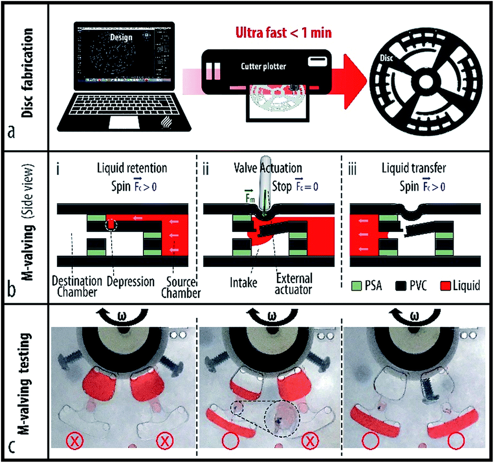 | ||
| Fig. 1 Rapid disc fabrication, and M-valving mechanism on centrifugal microfluidic platforms. (a) Ultra-rapid cutting of a PVC disc by a plotter machine. (b) (i) The M-valve made by a plotter blade, prevents liquid flow during disc spinning. (ii) The M-valve actuates by an external mechanical pressure. (iii) Spinning the disc transfers the liquid from the source chamber near the disc centre to the destination chamber near the outer rim of the disc. (c) Testing liquid retention by close M-valves, and liquid transfer from the opened M-valves at a high spin speed. | ||
2.2. Active mechanical valving
To enable retention and sequential release of reagents, we devised mechanical valves (M-valves) that are made by a simple cutter plotter, the same tool used to fabricate the rest of the microfluidic system in this study. The M-valve is an engraved depression between two horizontally aligned intakes that breaks when an external mechanical force is applied. To create a breakable thin wall, the penetration depth of the plotter's blade was adjusted to less than the total thickness of the PVC layer. Fig. 1b shows a schematic of the M-valving mechanism before and after mechanical actuation of the valve. A series of valves were tested and no leakage was observed up to 7000 rpm, i.e. the maximum speed of our spinning system, and equivalent to 1727 rfc and 2470 rfc (see Fig. 1c). It was shown that a cutter plotter enables low-cost fabrication of microfluidic cartridges with embedded active M-valves.3. Materials and method
In this section, we present the design and fabrication of two microfluidic cartridges with series of M-valves. The first microfluidic disc is designed based on an immunoassay protocol from whole blood. The second cartridge is a miniaturized chromatography system and is used for studying the capability of a modified resin (i.e. Sepharose 6B-PEG5000) for the isolation and recovery of monoPEGylated ribonuclease (RNase).3.1. Immunoassay disc
The immunoassay design, is comprised of several chambers for blood serum separation, sample metering, and the storage of reagent and washing buffers (see Fig. 2a). Moreover, it contains a siphon microchannel that allows the retention of reagents in the reaction (detection) chamber and their transfer to a waste chamber. The breakdown of the seven-layer immunoassay disc is shown in Fig. 2b. From bottom to top, the first layer is a featureless PVC disc. The second layer is a PSA with cut-outs in the shape of M-valves' intakes, microchambers and a siphon channel. The third and fourth layers are PVC and PSA similar to the second layer and are used to provide a larger volume. The fifth layer contains crescents (i.e., the depressions) of M-valves and cut-outs of microchambers. The PSA disc (sixth layer) on top of the M-valves contains cut-outs larger than the microchambers to connect the chambers to the top of their corresponding valves. The top layer is a PVC disc that contains venting and injection holes. The sequential functions on this microfluidic disc are designed based on the protocol of an enzyme-linked immunosorbent assay (ELISA) which are demonstrated in Section 4.1.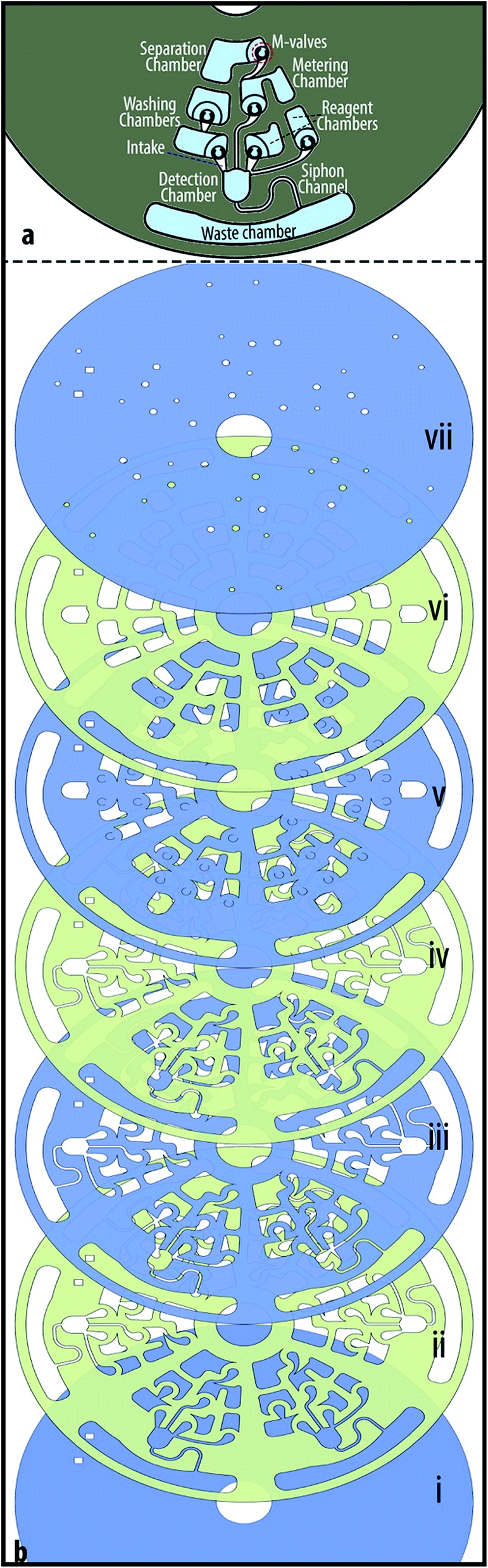 | ||
| Fig. 2 Design and layers of the immunoassay disc. (a) Design of the microfluidic disc for an immunoassay from whole blood. (b) The layer by layer assembly of the immunoassay disc. | ||
3.2. Chromatography cartridge
The chromatography cartridge is designed based on the hydrophobic interaction chromatography (HIC) technique to test a modified resin for isolation of monoPEGylated RNase A.33 For general information about PEGylation, and the modified resin please read ESI Section B.† The cartridge in this case contains six source chambers with M-valves for washing solution, sample and elution buffers (see Fig. 3a). The sample is 100 μl RNase A monoPEG (1.5 mg ml−1), and the buffers are different mixture of phase A and phase B; phase A is composed of 25 mM potassium phosphate pH 7.0, containing 1.5 M ammonium sulfate ((NH4)2SO4); and phase B contains 25 mM potassium phosphate, pH 7.0. In addition, the cartridge contains a collection chamber, and a reaction chamber (column) that is packed with a modified Sepharose 6B. The preparation process of Sepharose 6B-PEG5000 (i.e., the modified resin) is detailed in ESI Section B-(i).†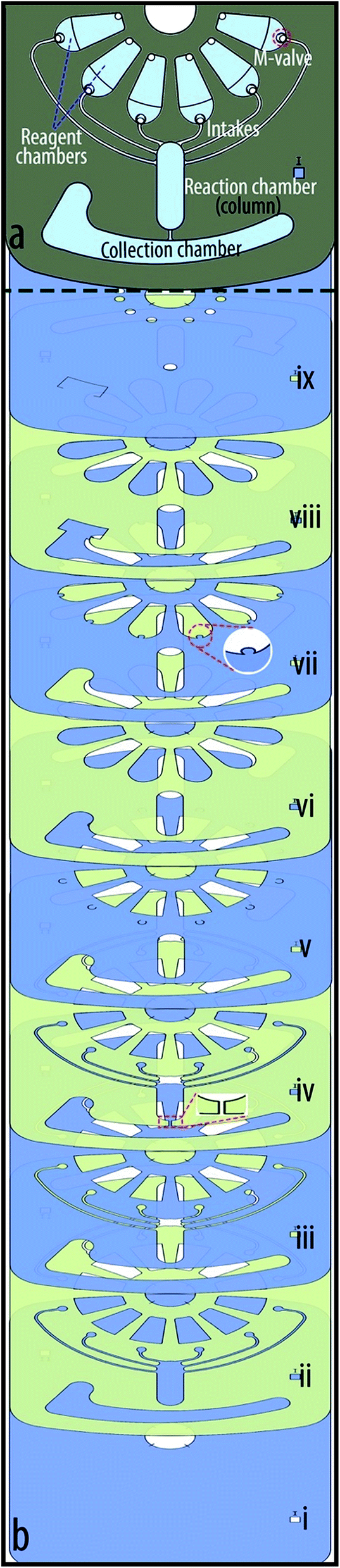 | ||
| Fig. 3 Design and assembly of the chromatography cartridge. (a) Design of the microfluidic platform based on the hydrophobic interaction chromatography (HIC) technique for mono-PEGylated RNase isolation. (b) Breakdown of the nine-layer chromatography cartridge. | ||
The breakdown of the nine-layer chromatography cartridge is shown in Fig. 3b. Similar to the previous disc, the first layer is a PVC and is used as the base. The second layer is a PSA and third layer is a PVC, both containing all microchambers and intakes. The fourth layer is a PSA with an additional microchannel that connects the reaction chamber (column) to the waste chamber. Embedding the microchamber in the tiny PSA layer enables trapping the resin in the column, while transferring the liquids to the waste chamber at high speeds. Similar to the previous disc, the fifth layer contains depressions (crescents) of M-valves and cut-outs of microchambers. The sixth layer is a PSA with cut-outs larger than the source chambers to create intakes that allow liquids to move from the source chambers to the top of the M-valves. In comparison to the immunoassay disc, this cartridge has additional PVC and PSA layers to enable the manipulation of larger liquid volumes. The larger space between the top PVC layer and the M-valves introduced difficulties for the actuation of the valves. To overcome this problem, we added semicircles to chamber design in the seventh layer to facilitate transfer of external mechanical force to the M-valve (see Fig. 3b-(vii)). The next layer is a PSA and the top layer is a PVC that contains injection and extraction holes. Experiment aimed to explore the potential of Sepharose 6B-PEG5000 for isolation of monoPEGylated RNase with the chromatography cartridge is described in Section 4.2, and results are discussed in Section 5.2.
4. Experimentations
4.1. Automated immunoassay
Colored liquids were used here to demonstrate the application of M-valves for the sequential immunoassay protocol. Red, blue, green and yellow color liquid in the disc represent sample, washing solution, antibody and substrate solution in real immunoassays (e.g. sandwich ELISA), respectively. The disc was spun clockwise up to 2400 rpm for a minute to mimic the spin protocol for the separation of serum from blood. To aliquot the red liquid above the first valve, which represents separated blood serum, the first M-valve was actuated and the disc was spun clockwise at 2400 rpm. The centrifugal force transferred the liquid to the metering finger and then the excessive liquid volume to the waste chamber (see Fig. 4b). The second M-valve was actuated and the disc was spun at 2400 rpm clockwise. The induced pseudo forces transferred the aliquot to the reaction chamber and the siphon channel. When the liquid level in the chamber exceeded the pick of the siphon crest, the siphon actuated and the sample was transferred to the waste chamber. To retain the sample in the chamber for a long incubation period, disc could be spun counter-clockwise to prevent siphon actuation. Fig. 4c shows the first washing process after actuation of the third M-valve during spinning of the disc. Afterwards, the fourth M valve was actuated for incubation of green liquid that represents antibodies. To incubate the green liquid in the reaction chamber, the disc was spun counter-clockwise to prevent siphon actuation (see Fig. 4d). After the incubation step, the direction of rotation was changed to enable siphoning or to drain the reaction chamber from the green liquid. More details regarding the actuation of siphon by Euler force is presented in an article by Yongbo Deng et al.34 The same spin profile was used for the second washing step, after actuation of the fifth M-valve. Fig. 4e shows the instant at which the disc was stopped to change the direction of rotation to siphon the second blue liquid. Finally, the sixth M-valve was actuated and the disc was spun counter-clockwise and stopped to retain the yellow liquid, representing substrate in real assays in the reaction chamber (see Fig. 4f).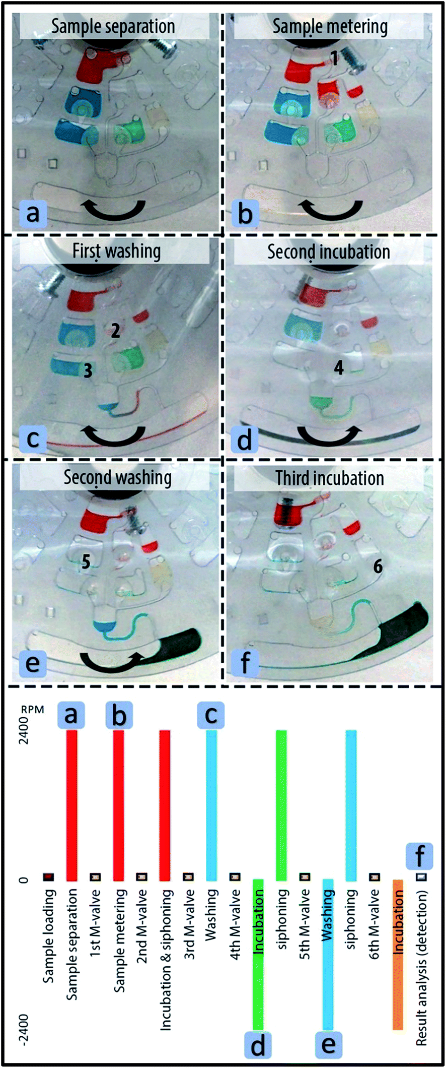 | ||
| Fig. 4 Sequential fluidic steps enabled by M-valves outlining a potential immunoassay protocol. Note that colored Di water was used for the demonstration of the fluidic protocol. (a) Separation step by spinning the disc at a high speed. (b) Metering step for aliquoting an exact sample volume. (c) Washing step for removing residual sample from the reaction chamber after the siphoning step. (d) Retention of the liquid in the reaction chamber, representing the incubation of a detection antibody. (e) Washing the residual green liquid after the siphoning step. (f) Stopping the disc for the retention of the last liquid/reagent in the reaction chamber that is require for sample analysis or detection. | ||
4.2. MonoPEGylated RNase isolation protocol
The column was charged with 340 μl of resin solution (30% Sepharose 6B-PEG5000, 70% ethanol) in four steps. In each step the disc was spun up to 2400 rpm to compress the resin, and to drain the ethanol from the column chamber. The microchannel at the bottom of the column is small enough to allow for the trapping of the resin in the column. After the ethanol was removed from the collection chamber, the column holding ∼100 μl of compressed resin was sealed (see Fig. 5a). The first M-valve was actuated and the disc was spun for three minutes (see Fig. 5a-(i)) to wash out the residual ethanol from the column. Fig. 5b shows the spin profile for the cartridge after actuation of each valve for washing, sample incubation, and elution steps. Each solution incubated in the column for one minute during which the disc was spun up to 800 rpm and then stopped. During the next two minutes, the spin speed of the cartridge was increased stepwise up to 2400 rpm. After removing the waste solution from the collection chamber, the second M-valve was actuated and the disc was spun to enable the resins to absorb the suspended monoPEGylated RNase (see Fig. 5b-(ii)). After the protein absorption step, the waste liquid in the collection chamber was extracted for further analysis to evaluate the protein absorption efficiency the resin. Similar to the previous fluidic steps, the four elution buffers were sequentially passed through the column (see Fig. 5b-(iii) and (iv)), and collected for evaluation of RNase recovery efficiency. For protein absorption and recovery rate, the liquid from the collection chamber was read at 280 nm. The analysis of the protein absorption and recovery by the modified resin and stepwise HIC using the chromatography cartridge is discussed in Section 5.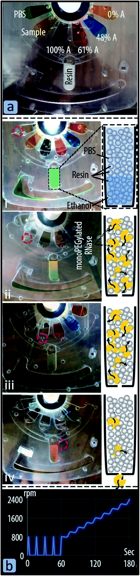 | ||
| Fig. 5 Sequential fluidic steps on chromatography cartridge for isolation of monoPEGylated RNase. (a) The cartridge was loaded with 100 μl sample, reagents and modified resins i.e. Sepharose 6B-PEG5000. (i) The first M-valve was actuated and the disc was spun to wash the residual alcohol, at which the resin was prestored, from the column. (ii) After removing the PBS from the collection chamber, the second M-valve was actuated and the disc was spun to incubate the RNase sample in the column. After the incubation step, the waste solution was collected from the collection chamber to analyse the sample isolation efficiency of the system. (iii, iv) In similar way to the previous steps, the other buffers were passed through the column and then collected to evaluate the recovery rate of RNase A monoPEG by the fluidic system. (b) Spin profile for the incubation of reagents in the column. The speed of 2400 rpm was adequate to drain the column from the sample and reagents. | ||
5. Results and discussion
5.1. On-site disc fabrication
A rapid and low-cost microfluidic disc fabrication technique enables the development of automated bioanalytical assays in EPOC and PON settings. We described an on-site disc fabrication method using only a cutter plotter which, compared to the router and laser CNCs of conventional disc fabrication processes, is fast, portable, low power consuming, quiet, safe, inexpensive and environmental friendly. In disc fabrication involving a CNC machine, a cutter plotter is usually required to cut microchambers and microchannels in the PSA layers. Therefore, the new disc fabrication process does not affect the fabrication precision of critical microfluidic components such as siphon channels and capillary valves. Thin PVC was selected for the disc construction due to its wide availability, high transparency and high decomposing/melting temperature (i.e.140 °C/160 °C) enabling the integration of thermally controlled assays such as PCR and LAMP. In summary, it is possible to develop microfluidic discs as lab tools and for various analytical applications with only a low-cost (e.g. $110–$3000) cutter plotter, PSA, PVC film, and a minimum training. The described method enables moving complex bioanalytical research studies to every school and research lab.5.2. M-Valving
We devised an active valving mechanism to enable the development of complex sequential bioanalytical assays on cutter-plotter-made discs. The M-valve fabrication process is compatible with that of microfluidic discs, and does not require any additional material or equipment. M-valves showed no leakage when tested up to spin speed of 7000 (2470 rcf), and actuate reliably with mechanical pressure. The valves can be actuated manually (and automatically with a robotic arm), which facilitates the development and rapid testing of new microfluidic platforms at EPOC settings. The cutter plotter was used for the development of the immunoassay disc, a comprehensive fluidic system that would allow for the integration of immunoassays from whole blood. The fluidic system included reagent storage and release, blood serum separation, serum metering, washing and reagent incubation processes.The second cartridge is a miniaturized chromatography system for studying the capability of the Sepharose 6B-PEG5000 for isolation of RNase monoPEG. Fig. 6 shows monoPEG absorption and recovery rate in the microfluidic cartridge. The absorption rate of RNase A monoPEG by the modified resin during the transfer of the sample in the column was 90%. After sequential releases of the elusion buffers, small percentages of proteins were eluted by buffers with 0% and 48% of phase A as the peak did not reached the baseline. However, the third elution step with the buffer containing 61% phase A provided higher recovery rate of 64% i.e. equivalent to 71% of the absorbed monoPEG. These results are consistent with those reported in the literature, confirming the possibility isolating the monoPEG by the modified resin and the buffer containing 61% phase A.33 The microfluidic cartridge for separation chromatography provided much less recovery rate compared to a reported value of the conventional chromatography system i.e. up to 96%. Nevertheless, the cartridge reduced the total required buffer volumes from 40 ml and 400 μl, and thus the time from about two hours to less than half an hour. In addition to preventing the need for an expensive chromatography machine, the rapid fabricated microfluidic discs enable multiplexing and provide flexibility for creating new experimental procedures. Further studies are required to optimize the interaction of sample and buffers in the column and eventually maximize the protein absorption and recovery rate. However, the main goal here was to demonstrate the use of rapid fabricated microfluidic discs as low-cost experimental setups in various kind of research studies.
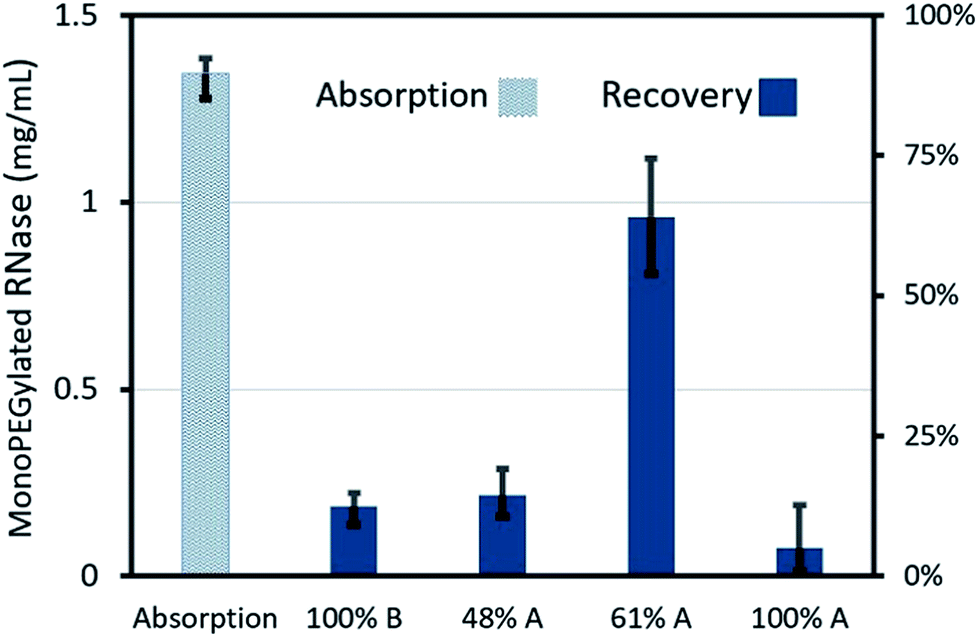 | ||
| Fig. 6 Absorption rate of RNase A monoPEG by the modified resin and their recovery by the four different buffers on the chromatography microfluidic cartridge. | ||
6. Conclusion
The ultra-rapid and low-cost fabrication method of centrifugal microfluidic cartridges by means of a cutter plotter increases the availability of the technology for EPOC and PON testing and research applications. Cutter plotters are as easily available, automated, easy-to-use, low-cost and compact, low power consuming, and portable as conventional printers. We selected the disc material to enable a wide range of applications, even PCR (not demonstrated in this study). Moreover, to enable reliable control over reagent retention and release, we devised the M-valves that are made by the same cutter plotter used in disc fabrication, preventing the need for any additional material, equipment and fabrication processes.We used a cutter plotter for fabrication of microfluidic discs with M-valves for diagnostic and research applications. The first microfluidic disc demonstrated the capability of the M-valves for automation of immunoassays from whole blood. The second microfluidic cartridge was a miniaturized chromatography system, and demonstrated the use of rapid fabricated platforms as a low-cost and flexible experimental setup. To our knowledge this is the fastest and least expensive fabrication technique of centrifugal microfluidic cartridges with active valves. We believe that this approach will enable the development, and small batch manufacturing of meaningful research and diagnostic platforms in EPOC and PON settings.
Conflicts of interest
There are no conflicts to declare.Acknowledgements
This work was financially supported by the CONACYT- DAAD PROALMEX 2015 program, grant no. 267726; and the Sensors & Devices group of Tecnologico de Monterrey (002EICII01).References
- S. T. Moen, C. L. Hatcher and A. K. Singh, PLoS One, 2016, 11, e0153137 Search PubMed.
- O. Strohmeier, M. Keller, F. Schwemmer, S. Zehnle, D. Mark, F. Von Stetten, R. Zengerle and N. Paust, Chem. Soc. Rev., 2015, 44, 6187–6229 RSC.
- M. Tang, G. Wang, S.-K. Kong and H.-P. Ho, Micromachines, 2016, 7, 26 CrossRef.
- L. Clime, D. Brassard, M. Geissler and T. Veres, Lab Chip, 2015, 15, 2400–2411 RSC.
- H. Kido, M. Micic, D. Smith, J. Zoval, J. Norton and M. Madou, Colloids Surf., B, 2007, 58, 44–51 CrossRef CAS PubMed.
- B. H. Park, J. H. Jung, H. Zhang, N. Y. Lee and T. S. Seo, Lab Chip, 2012, 12, 3875–3881 RSC.
- M. M. Aeinehvand, F. Ibrahim, S. W. Harun, I. Djordjevic, S. Hosseini, H. A. Rothan, R. Yusof and M. J. Madou, Biosens. Bioelectron., 2015, 67, 424–430 CrossRef CAS PubMed.
- Z. Cai, J. Xiang, H. Chen and W. Wang, Micromachines, 2016, 7, 89 CrossRef.
- G. Czilwik, S. Vashist, V. Klein, A. Buderer, G. Roth, F. von Stetten, R. Zengerle and D. Mark, RSC Adv., 2015, 5, 61906–61912 RSC.
- C.-Y. Koh, U. Y. Schaff, M. E. Piccini, L. H. Stanker, L. W. Cheng, E. Ravichandran, B.-R. Singh, G. J. Sommer and A. K. Singh, Anal. Chem., 2015, 87, 922–928 CrossRef CAS PubMed.
- H. McArdle, E. M. Jimenez-Mateos, R. Raoof, E. Carthy, D. Boyle, H. ElNaggar, N. Delanty, H. Hamer, M. Dogan and T. Huchtemann, Sci. Rep., 2017, 7, 1750 CrossRef PubMed.
- C. E. Nwankire, A. Venkatanarayanan, T. Glennon, T. E. Keyes, R. J. Forster and J. Ducrée, Biosens. Bioelectron., 2015, 68, 382–389 CrossRef CAS PubMed.
- J. Loo, H. Kwok, C. Leung, S. Wu, I. Law, Y. Cheung, Y. Cheung, M. Chin, P. Kwan and M. Hui, Biosens. Bioelectron., 2017, 93, 212–219 CrossRef CAS PubMed.
- K. Jackson, J. Borba, M. Meija, D. Mills, D. Haverstick, K. Olson, R. Aranda, G. Garner, E. Carrilho and J. Landers, Anal. Chim. Acta, 2016, 937, 1–10 CrossRef CAS PubMed.
- S. Smith, D. Mager, A. Perebikovsky, E. Shamloo, D. Kinahan, R. Mishra, S. M. Torres Delgado, H. Kido, S. Saha and J. Ducrée, Micromachines, 2016, 7, 22 CrossRef.
- I. J. Michael, T.-H. Kim, V. Sunkara and Y.-K. Cho, Micromachines, 2016, 7, 32 CrossRef.
- T.-H. Kim, V. Sunkara, J. Park, C.-J. Kim, H.-K. Woo and Y.-K. Cho, Lab Chip, 2016, 16, 3741–3749 RSC.
- J.-M. Park, M. S. Kim, H.-S. Moon, C. E. Yoo, D. Park, Y. J. Kim, K.-Y. Han, J.-Y. Lee, J. H. Oh and S. S. Kim, Anal. Chem., 2014, 86, 3735–3742 CrossRef CAS PubMed.
- D. J. Kinahan, S. M. Kearney, N. Dimov, M. T. Glynn and J. Ducrée, Lab Chip, 2014, 14, 2249–2258 RSC.
- Y. Kim, S.-N. Jeong, B. Kim, D.-P. Kim and Y.-K. Cho, Anal. Chem., 2015, 87, 7865–7871 CrossRef CAS PubMed.
- L. Swayne, A. Kazarine, E. J. Templeton and E. D. Salin, Talanta, 2015, 134, 443–447 CrossRef CAS PubMed.
- A. Phonchai, Y. Kim, R. Chantiwas and Y.-K. Cho, Lab Chip, 2016, 16, 3268–3275 RSC.
- M. M. Aeinehvand, F. Ibrahim, S. W. Harun, A. Kazemzadeh, H. A. Rothan, R. Yusof and M. Madou, Lab Chip, 2015, 15, 3358–3369 RSC.
- S. M. A. Mortazavi, P. Tirandazi, M. Normandie and M. S. Saidi, Microsyst. Technol., 2017, 23, 2767–2779 CrossRef CAS.
- B. L. Thompson, Y. Ouyang, G. R. Duarte, E. Carrilho, S. T. Krauss and J. P. Landers, Nat. Protoc., 2015, 10, 875–886 CrossRef PubMed.
- S. Hosseini, M. M. Aeinehvand, S. M. Uddin, A. Benzina, H. A. Rothan, R. Yusof, L. H. Koole, M. J. Madou, I. Djordjevic and F. Ibrahim, Sci. Rep., 2015, 5, 16485 CrossRef CAS PubMed.
- E. Duffy, R. Padovani, X. He, R. Gorkin, E. Vereshchagina, J. Ducrée, E. Nesterenko, P. N. Nesterenko, D. Brabazon and B. Paull, Anal. Methods, 2017, 9, 1998–2006 RSC.
- Y.-J. Chan, T.-H. Yuan, H.-C. Sun and T.-C. Lin, Aerosol Air Qual. Res., 2016, 16, 2216–2226 CrossRef.
- M. Focke, F. Stumpf, B. Faltin, P. Reith, D. Bamarni, S. Wadle, C. Müller, H. Reinecke, J. Schrenzel and P. Francois, Lab Chip, 2010, 10, 2519–2526 RSC.
- S. Okamoto and Y. Ukita, RSC Adv., 2017, 7, 35869–35874 RSC.
- I. Banerjee, T. Salih, H. Ramachandraiah, J. Erlandsson, T. Pettersson, A. Araújo, M. Karlsson and A. Russom, RSC Adv., 2017, 7, 35048–35054 RSC.
- M. C. Giuffrida and G. Spoto, Biosens. Bioelectron., 2017, 90, 174–186 CrossRef CAS PubMed.
- A. Hernández-Martínez and O. Aguilar, Sep. Purif. Technol., 2014, 136, 190–198 CrossRef.
- Y. Deng, J. Fan, S. Zhou, T. Zhou, J. Wu, Y. Li, Z. Liu, M. Xuan and Y. Wu, Biomicrofluidics, 2014, 8, 024101 CrossRef PubMed.
Footnote |
| † Electronic supplementary information (ESI) available. See DOI: 10.1039/c7ra11532f |
| This journal is © The Royal Society of Chemistry 2017 |