 Open Access Article
Creative Commons Attribution 3.0 Unported Licence
A micro-sized Si–CNT anode for practical application via a one-step, low-cost and green method†
Chao Li a,
Yuhang Jub,
Li Qib,
Hideya Yoshitakec and
Hongyu Wang*b
aCollege of Chemical Engineering and Energy Technology, Dongguan University of Technology, Dongguan 523808, China
bState Key Laboratory of Electroanalytical Chemistry, Changchun Institute of Applied Chemistry, Chinese Academy of Sciences, 5625 Renmin Street, Changchun 130022, China. E-mail: hongyuwang@ciac.ac.cn; Fax: +86-431-85262287; Tel: +86-431-85262287
cFaculty of Engineering, Yamagata University, Jyonan 4-3-16, Yonezawa 992-8510, Japan
First published on 1st December 2017
Abstract
Silicon (Si) has been used in Li-ion batteries (LIBs), and considerable progress has been achieved in design and engineering with improved capacity and cycling. However, large-scale application of Si-based anodes is hindered owing to the wide use of toxic raw materials, high manufacturing cost, limited capacity and unpalatable tap density. Herein, we describe a low-cost and green route to solve these problems. Composite Si–carbon nanotube (CNT) spheres were synthesized using a scalable method: rotary spray drying. These spheres were interspersed by many CNTs and wrapped Si nanoparticles (SiNPs) within them. Due to slightly rigid structure of CNTs, many void spaces in spheres could be preserved during the agglomeration of spheres. These voids could accommodate the volume expansion of Si particles and promote a stable integral structure during cycling. Importantly, this micron-grade material could improve the volume density and tap density to achieve high energy density. The prepared material showed promising reversible capacity of 2500 mA h g−1 with retention of 98% during 500 cycles. Ultra-fast discharge–charge (900 mA h g−1 at 20C) was achieved owing to the crosslinking effect between CNTs and SiNPs in these spheres. Moreover, a high-performance Si material was actualized via a simple industrial method rather than a complex synthesis.
1. Introduction
Over recent decades, the pursuit of lightweight and longevity has primarily driven the considerable progress made in energy storage and new chemical systems, especially in the field of lithium ion batteries (LIBs). Currently, LIBs have an ever-growing demand to achieve longer lifetimes in the digital field and, most notably, energy and power density are essential for the driving range in electric vehicles. Beyond the fact that intercalation-based materials can break through the limitations of Li ions, insertion into crystallographic sites can achieve a greater proportion of storage. Silicon (Si) anodes are the most promising non-intercalation materials compared with the graphite anode1–3 due to their high specific capacity (4200 mA h g−1),4 plentiful availability, and environmental friendliness.With regard to applications, a long life is one of the basic conditions for advanced energy. The key points are to increase the stability of the material and electrode configuration, and to decrease the reaction activity at the interface. However, the cycling retention of Si-based materials is the main drawback limiting a sustainable lifetime.5,6 Alloying–dealloying processes lead to severe volume changes and result in electrode-level cracking and failure, or loss of electrical contract between each electrode. In most cases, a nano-structure and three-dimensional nano-design provide the ideal route to offset volume expansion on electrode integrity, and allow the short-distance transmission of Li ions between active particles and the conductive phase.7,8 However, the high activity of nanoparticles (NPs) usually leads to high initial irreversible capacity, as well as low tap density, high synthesis costs, and mismatching of the technology that needs to be assembled.9–12 Hence, the use of nanoscale materials is unlikely.
At the industrial scale of LIB manufacture, micron-grade particles have been employed consistently as the most active material of LIBs. Such micron-grade particles contain LiFePO4, LiCoO2, or graphite to reduce the surface activity of the material.13,14 Active material of larger size can lead to high tap density to meet the volumetric density needed for commercial applications.1,2,4 Therefore, in this way, designing micron-grade Si material with low expansion effects becomes an effective way to improve the electrochemical performance and meet application needs.
There are two main approaches towards such a strategy: (i) pre-designed void spaces near Si particles in large-size materials to accommodate the volume expansion;15–17 (ii) embedding Si particles into a dense carbon matrix to buffer and limit large changes in volume.18–20 However, (i) requires a complex production method of extreme expense, an intolerant rolling technique, and is not suitable for manufacturing. Also, the Si-embedded composites, in general, offer limited capacity (<1000 mA h g−1) to maintain acceptable stability.21,22
In addition, rate capability is an important feature for LIBs.3,23,24 Si anodes of alloying type (which are different from layered graphite material) often limit transport kinetics owing to slow diffusion of ions or long pathways.25,26 After increasing the size of microparticles, fast charge–discharge is a huge challenge, and depends critically on the rate of migration of Li ions through active material.27,28 Therefore, a highly conductive material and short length of ion diffusion within large particles are key features.
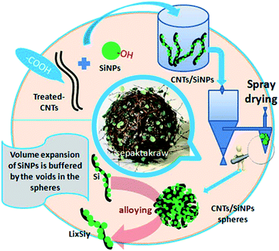
In the present study, a convenient strategy was proposed to solve the problems mentioned above. Then, a micron-sized material was synthesized in one step by a reliable industrial method, rotary spray drying,25,29,30 which is a common method for the manufacture of low-cost materials on a large scale.26,31–34 Herein, Si nanoparticles, as the starting materials, were granulated into micron-grade spheres accompanied with carbon nanotubes (CNTs). These interlaced and interspersed porous spheres comprised many individual and loose areas in a random-weave array to reach high stability. During spray drying, long tubes interspersed irregularly in the exterior/interior of spheres (Scheme 1), and many void spaces were preserved owing to the rigid support of CNTs. With the formation of LixSiy, the increasing volume occupied void spaces without affecting the whole structure. Different from the elaborate Si nanostructures created previously, this strategy made full use of the shape structures and properties of SiNPs and CNTs to self-assemble porous spheres compared with complex syntheses. Though a continuous synthesis in a water/air medium, environmentally unfriendly substances and expensive auxiliary material were not needed. Hence, it was suitable for industrial applications to overcome the high-cost barriers of nano-designed materials.35
2. Experimental section
2.1 Material synthesis
SiNPs of diameter 20 nm were prepared by the magnesium-based thermal reduction of silicon dioxide (SiO2). Then, SiO2 material was calcinated for 24 h at 800 °C in Ar gas.36,37 Si particles were placed in an autoclave under a high temperature to modify the hydroxyl groups on the Si surface by water vaporization.38 After a period of time, the hydroxylated-Si was removed rapidly and washed to maintain stability. CNTs (10 nm × 1 μm) were purchased. Modification of carboxyl groups on the surface of CNTs is a common method of modification. We used the immersion method in piranha solution. Under certain conditions, the groups in piranha solution can substitute some of the sites on CNT walls to produce oxide sites. Then, carboxylic-CNTs can be obtained.39,40Using the spray-drying method, the modified SiNPs and CNTs could be dispersed in aqueous solution to obtain a uniform solution system. The solution was introduced into the spray-drying system at a flow rate of 0.5 mL min−1 through a creeping pump. Liquid droplets were “thrown” into the dryer at high speed. At high temperature, the liquid droplets lost water rapidly so that hydroxyl-SiNPs could be adsorbed onto the surface of carboxylic-CNTs by chemical bonds. Owing to the high specific area of CNTs, many particles accumulated gradually and increased in size to become stable micron-grade spheres with irregular arrangements. Because the CNTs had rigidity, there were plenty of voids within and on the surface of the microspheres. This provided many void spaces for the volume change of Si during the electrochemical process, and ensured the stability of the overall structure of the particles. Production of pure Si microspheres (PSs) was done using the method described above, and the solution contained only SiNPs without CNTs.
2.2 Material characterization
The weight changes of the SiNPs, CNTs and CNTs–Si microspheres (CSs) were measured in air using a thermogravimetric analysis (TGA) system (Mettler Toledo, Columbus, OH, USA). X-ray diffraction (XRD) studies were carried out using a D8 advanced diffraction system (Bruker, Germany). Scanning electron microscopy (SEM) was carried out using a XL-30 microscope (Quanta FEG; FEI/Philips, the Netherlands). Transmission electron microscopy (TEM) measurements were done on a TEM microscope (Tecnai G2 F20 S-Twin; FEI/Philips) equipped with a SuperTwin objective lens with a coefficient of spherical aberration of 1.2 mm and operating at 200 kV. Nitrogen adsorption–desorption isotherms were collected at 77 K on a Quantachrome (Hook, UK) instrument and used for measurements of the specific surface area (SSA) and pore-size distribution at 1–100 nm.2.3 Electrode electrochemistry
Working electrodes were prepared by coating a slurry containing an active material (CSs), PSs, SiNPs or SiMPs with 30% CNTs, along with 10 wt% addition of polyacrylic acid (molecular weight, 450![[thin space (1/6-em)]](https://www.rsc.org/images/entities/char_2009.gif) 000) in N-methyl-2-pyrrolidone on copper foil (12 μm). The electrodes were calendared by a tablet machine and degassed in a vacuum for ≥4 h at 100 °C. Half-cells were assembled in an Ar-filled glove box. They comprised: (i) a disk (0.785 cm2) of the working electrode; (ii) a glass-fiber separator soaked with a 1 M LiPF6 electrolyte dissolved in 3
000) in N-methyl-2-pyrrolidone on copper foil (12 μm). The electrodes were calendared by a tablet machine and degassed in a vacuum for ≥4 h at 100 °C. Half-cells were assembled in an Ar-filled glove box. They comprised: (i) a disk (0.785 cm2) of the working electrode; (ii) a glass-fiber separator soaked with a 1 M LiPF6 electrolyte dissolved in 3![[thin space (1/6-em)]](https://www.rsc.org/images/entities/char_2009.gif) :
:![[thin space (1/6-em)]](https://www.rsc.org/images/entities/char_2009.gif) 7 ethylene carbonate/ethylmethyl carbonate with 10 wt% fluoroethylene carbonate and 2 wt% cinylene carbonate; and (iii) a Li plate as the counter and reference electrode. Coin cells were used to carry out a cycling test in galvanostatic mode at room temperature.
7 ethylene carbonate/ethylmethyl carbonate with 10 wt% fluoroethylene carbonate and 2 wt% cinylene carbonate; and (iii) a Li plate as the counter and reference electrode. Coin cells were used to carry out a cycling test in galvanostatic mode at room temperature.
3. Results and discussion
Rotary spraying is a scalable, continuous method used to obtain micron-grade composite Si-based materials. Fig. 1a demonstrates the synthetic process for CSs. SiNPs as raw materials are enriched in hydroxyl groups on the surface by activation of the original siloxane functionalities via heating in water,38,41 whereas the solution described above is added to CNTs as another raw material via carboxylic functionalities. Subsequently, the CNTs were dispersed in water upon gentle stirring. The SiNPs with high surface energy, along with the van der Waals forces between hydroxyl and carboxylic groups, were adsorbed on the surface of CNT walls. The formation of a stable SiNPs/CNTs solution was particularly important to promote agglomeration during spray drying. The solution was introduced into the machine by a peristaltic pump, driven rapidly into a chamber by atomization, and dried instantaneously at high temperature (180 °C). This process promoted rapid dehydration between groups, leading to the formation of stable Si–O–C![[double bond, length as m-dash]](https://www.rsc.org/images/entities/char_e001.gif) O–CNT groups. The CNTs and adsorbed-SiNPs were rotated at high speed and were in contact with gaseous fluids. Small particles have a natural tendency to form larger spheres. Thus, NPs assembled spontaneously into micron-grade spheres in an irregular mode by high-speed rotation. Due to the special structure of CNTs, these SiNPs were not granules but dense particles, and formed loose and porous structures supported by CNTs. Also, an irregular arrangement was formed in the void spaces in the spheres.
O–CNT groups. The CNTs and adsorbed-SiNPs were rotated at high speed and were in contact with gaseous fluids. Small particles have a natural tendency to form larger spheres. Thus, NPs assembled spontaneously into micron-grade spheres in an irregular mode by high-speed rotation. Due to the special structure of CNTs, these SiNPs were not granules but dense particles, and formed loose and porous structures supported by CNTs. Also, an irregular arrangement was formed in the void spaces in the spheres.
The SEM images in Fig. 2a–d reveal a prepared composite material composed of a large number of pores and voids on the surface, and which appeared as non-compact spheres. Also, many SiNPs were located within the spheres with CNTs interspersed among them. A porous sphere structure was formed by the rigidity of CNTs supporting them, whereas many pores could serve as void spaces to meet the volume expansion from Si (Fig. 1c and d). In addition, the chemical bonds between SiNPs and CNTs helped to stabilize the integral structure of the spheres. This special structure was aggregated spontaneously from SiNPs and CNTs owing to the different shape of particles and CNTs themselves without control by a complicated synthesis. Therefore, the synthesis could be realized at low cost and at a large scale. In addition, SEM showed that most particle sizes ranged from 1 μm to 10 μm (mean, ≈4.6 μm) (Fig. 2e). Thus, an important feature of these materials was obtaining a higher volume density after their size had been increased. Fig. 2f demonstrates the contrast photograph for four types of Si materials under the same weight. A detailed image is shown in Fig. S1.† These CSs had far higher volume density (0.81 g cm−3) than SiNPs, and it was close to that for SiMPs and PSs using the same synthetic method. Relatively, the raw material (SiNPs) of CSs was shown to have extremely low volume density. For both materials, it is shown that high volume density was dependent upon the large diameter of micron-grade particles. A Si material of high volume density could be prepared from a thinner electrode to obtain the high areal capacity and volume energy density of LIBs.
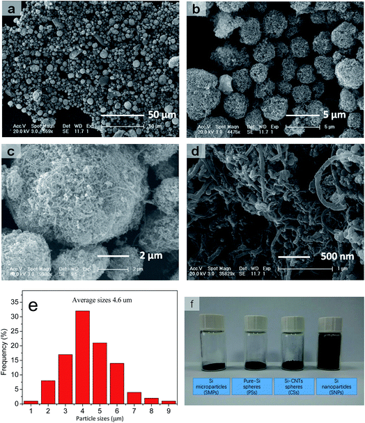 | ||
| Fig. 2 (a–d) SEM images at different magnifications. (e) Statistical data for distribution analyses. (f) Comparison of volume on 0.2 g samples in 5 mL vials. | ||
Fig. 3a shows the TEM images of CSs material to reveal many CNTs and SiNPs within spheres. Also, many voids had formed and spread in the interior of spherical particles (Fig. 3b and c). The observed voids (Fig. 3b and c) had an irregular structure of approximate diameter 1–100 nm within spheres, and the most of the voids were larger than the size of SiNPs (20 nm). Brunauer–Emmett–Teller (BET) analyses revealed the pore-size distribution in CSs to range from 1 nm to larger areas (Fig. 2d). The pore size was mainly 30–50 nm, and was larger than the diameter of SiNPs. For these pores, nitrogen adsorption–desorption in BET tests demonstrated the stability and reversibility within spheres (Fig. 3e).42 After increasing in size, the SSA of 67 m2 g−1 also showed an obvious decrease corresponding to that of the SiNPs (189 m2 g−1) in Fig. S2a and b,† even though it had a rich porous structure. A stable porous structure and lower surface area have important roles in cycling stability. Apart from the positive effects on volume expansion, a porous structure can also provide channels for the migration of electrons and ions through the walls of CNTs. Also, the TGA curves (Fig. 3f) of SiNPs in air (red curve) showed some weight loss owing to the decomposition of hydroxyl and other groups at 200 °C, whereas CNTs (blue curve) were completely burnt before 600 °C. Remarkably, the weight of CSs lost was 18% (which corresponded to the CNTs accounting for 30% wt of CSs), which showed that most of the SiNPs and CNTs were dehydrated in this process. The XRD lines (Fig. S3†) indicated a stable structure of CSs and unaffected crystals after granulation at 180 °C.
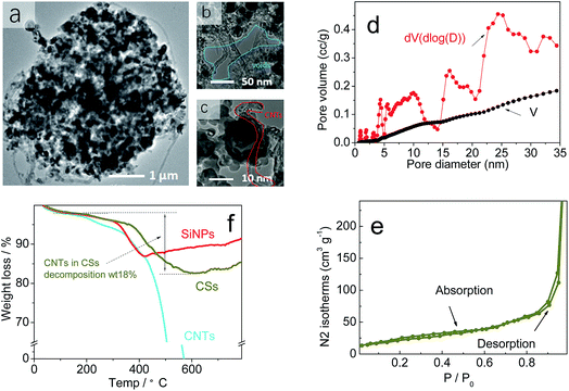 | ||
| Fig. 3 (a–c) TEM image, (d) pore volume (V) and dV of BET. (e) The N2 adsorption–desorption isotherms of BET on CSs. (f) Thermogravimetric analysis (TGA) of CSs in air. | ||
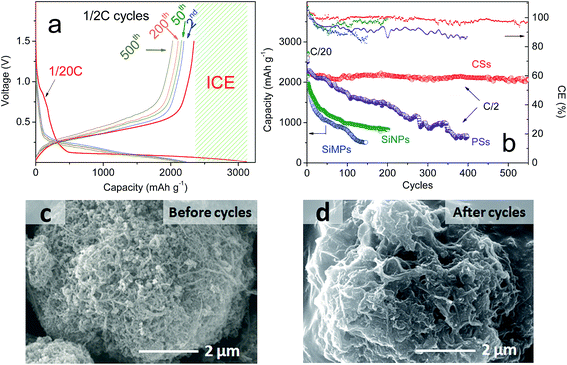
With “ideal” porous spheres, superior electrochemical properties are also very important for the practical use of LIBs. Herein, half-cells were used to determine the performance of the as-prepared CSs. All specific capacities were based on a 70% mass of silicon and 30% CNTs. As shown in Fig. 4a, the CSs could deliver an initial capacity of 3080.8 mA h g−1 and reversible capacity of 2343.12 mA h g−1 at a rate of C/20. Also, the initial coulombic efficiency showed the formation of a solid electrolyte interface that was lower than that of graphite (≈90%), but the capacity was far greater than that of the latter. Upon further cycling, the capacities also decreased slightly and remained at this level after the second cycle. After 200 cycles, a capacity of >2260.1 mA h g−1 remained and the retention was >96.2%. This capacity retention can be maintained at >99% without the unstable period noted in previous cycles. After 500 cycles, >2060.3 mA h g−1 remained and the retention was >96%. In addition, the synthesized PSs without CNTs using the same method demonstrated a different electrochemical performance (Fig. 4b). Also, we compared the properties of SiNPs (primary Si) and SiMPs (Si crystals of diameter 2 μm). In addition, the cycling performance was contrasted at a constant current of C/2 (1 A g−1). These materials had poor cyclicity, the reasons for which varied. For example, for SiNPs of high surface area, strong expansion and particle cracking probably led to cycling instability. For PSs, it was difficult to improve their stability even though the tap density increased with larger particle size (Fig. 2f). To investigate the causes, the SEMs of CSs and PSs were compared. After 100 deep cycles, the morphology of CSs (Fig. 4c, d and S5†) revealed an irregular distribution of SiNPs and CNTs with plenty of pores. Repeated volume expansion made it difficult to distinguish individual NPs, which contributed to the stable structure of spheres. In contrast, PSs demonstrated a “loose” architecture after cycles. Such secondary spheres from pure Si had no obvious positive effects on volume. Cyclic voltammetry (Fig. 5a) revealed that excellent reversibility could be obtained irrespective of oxidation or reduction peaks. After cycling, the voltage plateau of discharge–charge remained stable without severe polarization during repeated expansion. The cyclic stability mentioned above suggests that a sufficient number of void spaces were available to accommodate the volume expansion from SiNPs in CSs. Also, for cycling, the stable porous structure must maintain an excellent morphology during repeated intercalation of Li ions and expansion of LixSiy. After many cycles, the voltage plateau of discharge–charge curves must also maintain stability without severe polarization.
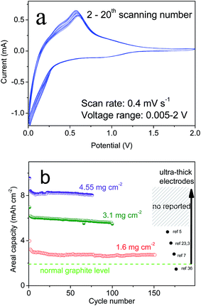 | ||
| Fig. 5 (a) Electrochemical curves of CV at 2–20 scans and (b) areal capacity of several types of Si materials. | ||
For a simple but promising strategy, excellent cycling capability can reveal the necessity of pre-designed void spaces in particles. However, one report showed that excessive control of a synthetic process and material morphology can increase the cost significantly and reduce the yield. Based on the different shapes of CNTs and SiNPs themselves, the spontaneous formation of void spaces using highly effective technology is ideal. In such spheres, the SiNPs are wrapped tightly in spheres through disordered and interspersed CNTs, and then are stabilized further by chemical interactions with CNT walls. This type of structure can be analogized to the use of steel-reinforced concrete to build a skyscraper.
Also, it is known that a large material can improve the tap density and loading mass of an electrode. Herein, we prepared several ultra-thick electrodes to measure the cycling performance (Fig. 5b). As shown in Fig. 5, the areal capacities of CSs remained stable at 3.5–8 mA h cm−2, which corresponded to a loading mass (active Si) of 1.6, 3.1, and 4.55 mg cm−2. Also, a high tap density was associated with a high loading mass and stable electrode structure. With regard to the industrial production of graphite, ultra-thick electrodes could also maintain stable cycling to avoid peeling and cracking issues. In most studies, high capacities and long cycling have typically been based on an extremely low loading mass for Si-based anodes. In contrast, graphite possessed a tap density of 1.02 g cm−3 (Fig. S4†), a loading mass ≤6.2 mg cm−2 but an areal capacity of only 1.5 mA h cm−2 owing to low specific capacity (∼372 mA h g−1). The SiMPs electrodes showed poor cycling but high areal capacity (∼4 mA h cm−2) at the start. For SiNPs, the loading mass was only one-tenth that of CSs due to the low tap density of the nanomaterial (Fig. 2f). With the strict requirement of an ultra-thick electrode, retention of high capacity was indicative of a stable structure, which confirms that the design was successful.
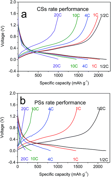
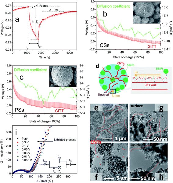
CNTs have outstanding electronic conductivity owing to a special carbon structure.43–45 Under the performances mentioned above, the power density of LIBs is also an essential feature needed for a large current discharge–charge. Thus, the half-cell from CSs was placed at a high current of 1/2C to 20C to test the discharge–charge capacity (Fig. 4a). Capacity retention of 96% and 81% at rates of 1C and 4C, respectively, versus C/2, were observed. Even under ultra-high rates of 20C it could still reach a capacity of 900 mA h g−1, and beyond the theoretical capacity of graphite materials. This rate property was far in excess that of other electrodes (Fig. 6b, S6a and b†) composed of PSs, SiMPs and SiNPs even with the addition of CNTs (30% wt). Ultra-fast discharge–charge suggested that the micron-grade particles did not prevent the rapid diffusion of Li ions from the surface to the interior of particles. To study this issue further, the diffusion coefficients of Li ions for both materials were tested by the generalized integral transform technique. This testing technology (Fig. 7a) can be used to study the rate of movement of ions in a particle. In CSs electrodes (Fig. 7b), the DLi+ was 10−6–10−10 cm2 S−1 depending on the different potential used. Also, the diffusion rate of ions in CSs was far faster than that for PSs electrodes (Fig. S7†).
The schematic in Fig. 7d shows the route of ultra-fast transfer of ions from the surface to the interior of CSs. During insertion or extraction, CNTs could provide an excellent transmission medium for ion movement. Another reason that should be considered is the dense distribution of Si–O–C![[double bond, length as m-dash]](https://www.rsc.org/images/entities/char_e001.gif) O–CNTs and abundant anion channels for the movement of cations (Li ions). Also, the irregular array of CNTs in the interior (Fig. 7e–h) provided a sufficient surface area to make contact with the electrolyte to enable transmission of Li ions at the interface. In addition, the high conductivity of CNTs (102–106 S cm−1) allowed electrons to reach the surface of attached SiNPs during discharge–charge rapidly.46,47 Thus, the CNTs offset the low conductivity of the Si bulk, thereby achieving the outstanding rate performances without noticeable polarization. During alloying, changes in resistance were detected by electrochemical impedance spectroscopy (EIS) (Fig. 7i and S8a†) to determine the surface properties of the interface. The EIS curves showed a lower ion diffusion resistance of CSs in the liquid–solid phase than that of the PSs electrode,48,49 which was due mainly to the low frequency in the slope of the straight line (Fig. S8b†).
O–CNTs and abundant anion channels for the movement of cations (Li ions). Also, the irregular array of CNTs in the interior (Fig. 7e–h) provided a sufficient surface area to make contact with the electrolyte to enable transmission of Li ions at the interface. In addition, the high conductivity of CNTs (102–106 S cm−1) allowed electrons to reach the surface of attached SiNPs during discharge–charge rapidly.46,47 Thus, the CNTs offset the low conductivity of the Si bulk, thereby achieving the outstanding rate performances without noticeable polarization. During alloying, changes in resistance were detected by electrochemical impedance spectroscopy (EIS) (Fig. 7i and S8a†) to determine the surface properties of the interface. The EIS curves showed a lower ion diffusion resistance of CSs in the liquid–solid phase than that of the PSs electrode,48,49 which was due mainly to the low frequency in the slope of the straight line (Fig. S8b†).
4. Conclusion
We presented a promising strategy to solve the expansion problem of Si materials by a simple and environmentally friendly industrial method. Use of an inexpensive raw material without toxic accessory substances engenders obvious application advantages. By rotary spray drying, a Si composite material was obtained to meet industrial demands. Satisfactory electrochemical performance verified the superior stability of CNT–Si spheres to accommodate the volume changes observed during repeated discharge–charge. Ultra-high rates at 20C and high areal capacity of 8 mA h cm−2 were achieved without the need for a complex synthetic method. We believe that this low-cost and continuous-production method could be the basis to increasing the performance of commercial LIBs.Conflicts of interest
There are no conflicts to declare.Acknowledgements
This work was supported financially by National Natural Science Foundation of China (21673222).References
- J. B. Goodenough and Y. Kim, Chem. Mater., 2010, 22, 587–603 CrossRef CAS.
- J. Cabana, L. Monconduit, D. Larcher and M. R. Palacín, Adv. Mater., 2010, 22, E170–E192 CrossRef CAS PubMed.
- M. S. Whittingham, Chem. Rev., 2014, 114, 11414–11443 CrossRef CAS PubMed.
- M. T. McDowell, S. W. Lee, W. D. Nix and Y. Cui, Adv. Mater., 2013, 25, 4966–4985 CrossRef CAS PubMed.
- J. H. Ryu, J. W. Kim, Y. E. Sung and S. M. Oh, Electrochem. Solid-State Lett., 2004, 7, A306–A309 CrossRef CAS.
- X. H. Liu, L. Zhong, S. Huang, S. X. Mao, T. Zhu and J. Y. Huang, ACS Nano, 2012, 6, 1522–1531 CrossRef CAS PubMed.
- C. K. Chan, H. L. Peng, G. Liu, K. McIlwrath, X. F. Zhang, R. A. Huggins and Y. Cui, Nat. Nanotechnol., 2008, 3, 31–35 CrossRef CAS PubMed.
- M. Ashuri, Q. R. He and L. L. Shaw, Nanoscale, 2016, 8, 74–103 RSC.
- M. Wu, J. E. C. Sabisch, X. Song, A. M. Minor, V. S. Battaglia and G. Liu, Nano Lett., 2013, 13, 5397–5402 CrossRef CAS PubMed.
- H. Wu and Y. Cui, Nano Today, 2012, 7, 414–429 CrossRef CAS.
- J. R. Szczech and S. Jin, Energy Environ. Sci., 2011, 4, 56–72 CAS.
- Y.-M. Chiang, Science, 2010, 330, 1485–1486 CrossRef CAS PubMed.
- C. Masquelier and L. Croguennec, Chem. Rev., 2013, 113, 6552–6591 CrossRef CAS PubMed.
- J.-W. Choil and D. Aurbach, Nat. Rev. Mater., 2016, 1, 1–16 Search PubMed.
- G. Jo, I. Choi, H. Ahn and M. J. Park, Chem. Commun., 2012, 48, 3987–3989 RSC.
- N. Liu, H. Wu, M. T. McDowell, Y. Yao, C. Wang and Y. Cui, Nano Lett., 2012, 12, 3315–3321 CrossRef CAS PubMed.
- B. Hertzberg, A. Alexeev and G. Yushin, J. Am. Chem. Soc., 2010, 132, 8548–8549 CrossRef CAS PubMed.
- M. K. Datta and P. N. Kumta, J. Power Sources, 2007, 165, 368–378 CrossRef CAS.
- W.-R. Liu, J.-H. Wang, H.-C. Wu, D.-T. Shieh, M.-H. Yang and N.-L. Wu, J. Electrochem. Soc., 2005, 152, A1719–A1725 CrossRef CAS.
- S. H. Ng, J. Wang, D. Wexler, K. Konstantinov, Z. P. Guo and H. K. Liu, Angew. Chem., Int. Ed., 2006, 45, 6896–6899 CrossRef CAS PubMed.
- M. K. Datta and P. N. Kumta, J. Power Sources, 2006, 158, 557–563 CrossRef CAS.
- J. Shu, H. Li, R. Yang, Y. Shi and X. Huang, Electrochem. Commun., 2006, 8, 51–54 CrossRef CAS.
- B. Dunn, H. Kamath and J.-M. Tarascon, Science, 2011, 334, 928–935 CrossRef CAS PubMed.
- V. Etacheri, R. Marom, R. Elazari, G. Salitra and D. Aurbach, Energy Environ. Sci., 2011, 4, 3243–3262 CAS.
- U. Kasavajjula, C. S. Wang and A. J. Appleby, J. Power Sources, 2007, 163, 1003–1039 CrossRef CAS.
- P. Oh, S. J. Myeong, W. Cho, M.-J. Lee, M. Ko, H. Y. Jeong and J. Cho, J. Nanosci. Lett., 2014, 14(10), 5965–5972 CrossRef CAS PubMed.
- K. Persson, V. A. Sethuraman, L. J. Hardwick, Y. Hinuma, Y. S. Meng, A. van der Ven, V. Srinivasan, R. Kostecki and G. Ceder, J. Phys. Chem. Lett., 2010, 1, 1176–1180 CrossRef CAS.
- N. A. Kaskhedikar and J. Maier, Adv. Mater., 2009, 21, 2664–2680 CrossRef CAS.
- J. H. Ryu, J. W. Kim, Y.-E. Sung and S. M. Oh, Electrochem. Solid-State Lett., 2004, 7, A306–A309 CrossRef CAS.
- Y. Jin, N. Li, C. H. Chen and S. Q. Wei, Electrochem. Solid-State Lett., 2006, 9, A273–A276 CrossRef CAS.
- S. H. Ng, J. Wang, D. Wexler, K. Konstantinov, Z. P. Guo and H. K. Liu, Angew. Chem., Int. Ed., 2006, 45(41), 6896–6899 CrossRef CAS PubMed.
- S. H. Ng, J. Wang, D. Wexler, S. Y. Chew and H. K. Liu, J. Phys. Chem. C, 2007, 111(29), 11131–11138 CAS.
- X. Du, Z. Jiang, X. Meng, Z. Wang, H. Yu, M. Li and T. Tang, J. Phys. Chem. C, 2008, 112(17), 6638–6642 CAS.
- F. Iskandar, A. B. D. Nandiyanto, K. M. Yun, C. J. Hogan, K. Okuyama and P. Biswas, Adv. Mater., 2007, 19(10), 1408–1412 CrossRef CAS.
- J. J. Wang and X. L. Sun, Energy Environ. Sci., 2012, 5, 5163–5185 CAS.
- Z. H. Bao, M. R. Weatherspoon, S. Shian, Y. Cai, P. D. Graham, S. M. Allan, G. Ahmad, M. B. Dickerson, B. C. Church, Z. T. Kang, H. W. Abernathy, C. J. Summers, M. L. Liu and K. H. Sandhage, Nature, 2007, 446, 172–175 CrossRef CAS PubMed.
- F. H. Du, B. Li, W. Fu, Y. J. Xiong, K. X. Wang and J. S. Chen, Adv. Mater., 2014, 26, 6145–6150 CrossRef CAS PubMed.
- N. Delpuech, D. Mazouzi, N. Dupré, P. Moreau, M. Cerb and B. Humbert, J. Phys. Chem. C, 2014, 118, 17318–17331 CAS.
- C.-C. Li and Y.-W. Wang, J. Power Sources, 2013, 227, 204–210 CrossRef CAS.
- V. Meunier, J. Kephart, C. Roland and J. Bernholc, Phys. Rev. Lett., 2002, 88, 075506 CrossRef PubMed.
- A. Vidal, H. Balard, E. Papirer, M. Czemichowski, R. Erre, P. Levitz, H. V. Damme, J. P. Gallas, J. F. Hemedy, J. Lavalley, O. Barres, A. Burneau and Y. Grillet, Adv. Colloid Interface Sci., 1990, 33, 91–330 CrossRef.
- M. Li, X. H. Hou, Y. J. Sha, J. Wang, S. J. Hu, X. Liu and Z. P. Shao, J. Power Sources, 2014, 248, 721–728 CrossRef CAS.
- X.-L. Wu, Y.-G. Guo, J. Su, J.-W. Xiong, Y.-L. Zhang and L.-J. Wan, Adv. Energy Mater., 2013, 3, 1155–1160 CrossRef CAS.
- A. Varzi, D. Bresser, J. von Zamory, F. Müller and S. Passerini, Adv. Energy Mater., 2014, 4, 1400054 CrossRef PubMed.
- F. Y. Jin, S. Xiao, L. J. Lu and Y. Wang, Nano Lett., 2016, 16(1), 440–447 CrossRef CAS PubMed.
- Q. Zhang, J. Q. Huang, W.-Z. Qian, Y. Y. Zhang and F. Wei, Small, 2013, 9, 1237–1265 CrossRef CAS PubMed.
- B. Marc, H. C. David, L. M. Paul, G. C. Nasreen, A. Zettl, T. Andreas and R. E. Smalley, Science, 1997, 275, 1922–1925 CrossRef.
- H. D. Chen, Z. L. Wang, X. H. Hou, L. J. Fu, S. F. Wang, X. Q. Hu, H. Q. Qin, Y. P. Wu, Q. Ru, X. Liu and S. J. Hu, Electrochim. Acta, 2017, 249, 113–121 CrossRef CAS.
- X. H. Hou, M. Zhang, J. Y. Wang, S. J. Hu, X. Liu and Z. P. Shao, J. Alloys Compd., 2015, 639, 27–35 CrossRef CAS.
Footnote |
| † Electronic supplementary information (ESI) available. See DOI: 10.1039/c7ra11350a |
| This journal is © The Royal Society of Chemistry 2017 |

