 Open Access Article
ZSM-5 functionalized in situ with manganese ions for the catalytic oxidation of cyclohexane†
X. R. Niua,
J. Lia,
L. Zhanga,
Z. T. Leiab,
X. L. Zhaoa and
C. H. Yang *ab
*ab
aMIIT Key Laboratory of Critical Materials Technology for New Energy Conversion and Storage, School of Chemistry and Chemical Engineering, Key Laboratory of Micro-systems and Micro-structures, Ministry of Education, Harbin Institute of Technology, 150001 Harbin, People's Republic of China. E-mail: yangchh@hit.edu.cn
bKey Laboratory of Micro-systems and Micro-structures Manufacturing of Ministry of Education, Harbin Institute of Technology, Harbin 150001, China
First published on 31st October 2017
Abstract
We report the preparation of transition metal-containing ZSM-5 catalysts, which were active and selective for cyclohexane oxidation. Manganese ions were abundant and available for preparing Mn-containing ZSM-5 (Mn-ZSM-5) with an MFI structure. The catalytic properties of Mn-ZSM-5 for the mild oxidation of cyclohexane with hydrogen peroxide (H2O2) in the liquid phase were investigated. With different amounts of Mn4+ ions incorporated, the catalytic results varied with conversions of 21.21%, 20.72%, 30.66% and 19.53%, and selectivities to cyclohexanone and cyclohexanol (KA oil, SKA, mol%) of 96.26%, 94.11%, 97.41% and 97.27%. In summary, the prepared Mn-ZSM-5 catalyst is an effective catalyst for cyclohexane oxidation with H2O2 as an oxidant under mild conditions.
1 Introduction
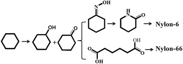
The partial oxidation of cyclohexane to cyclohexanol and cyclohexanone (also known as KA oil), important intermediates in the manufacture of nylon-6 and nylon-66, is of great commercial value (Scheme 1).1–3 KA oil is mainly obtained via the oxidation of cyclohexane using air or peroxide as the oxidant.4–6 Much research has been carried out in an attempt to reduce the over-oxidation that leads to unwanted products during the air oxidation reaction carried out at ∼443 K and ∼11 bar, which limits cyclohexane conversion to less than 10%.6–10 Furthermore, in present industrial production processes, homogeneous catalysts such as cobalt naphthenate are utilized as an initiator to promote the oxidation pathway. However, these homogeneous catalysts are difficult to separate from the reaction mixture, leading to serious environmental pollution. As is well known, hydrogen peroxide (H2O2, HP) is one versatile and green oxidant, due to the high fraction of active oxygen it contains, and the environmentally benign nature of its product (H2O) in oxidation reactions. Unfortunately, there have been few reports on the oxidation of cyclohexane with peroxide in the liquid phase. Therefore, the development of an efficient heterogeneous catalyst for the oxidation of cyclohexane with HP as oxidant is becoming increasingly attractive.In fact, many efforts have focused on developing new heterogeneous catalysts (such as zeolites) for this reaction. Thomas and co-workers11–14 demonstrated that Mn-, Fe- and Co-containing AlPO-series redox molecular sieves showed catalytic activity in a solvent-free system of cyclohexane oxidation by air. Furthermore, a number of transition metal (Mn, Zr, Cr, Ni, Co, Fe, Sn and Cu) containing molecular sieves were found to be active and selective for cyclohexane oxidation.15–20 Shul'pin et al.21 used a binuclear manganese (IV) complex ([LMnIV (O)3 MnIV L]2+, L: 1,4,7-trimethyl-1,4,7-triazacyclononane) as a catalyst to achieve a better reaction efficiency. Notably, manganese is an effective element in the catalytic oxidation of cyclohexane. However, the technology in which cyclohexane is oxidized by oxidants (O2, H2O2 and alkyl hydroperoxide) to produce cyclohexanone and cyclohexanol has not improved much, since it is difficult to maintain both high conversion and selectivity simultaneously under mild conditions.22
ZSM-5 is a typical molecular sieve, with an MFI topological structure, and is an easily synthesized microporous material, resistant to high temperature and pressure. Moreover, it can be functionalized by incorporating other functional components23–26 and supporting metal oxides to improve its catalytic performance.27–29 For example, nano-crystalline ZSM-5 functionalized with Cu has been explored for the selective oxidation of toluene to benzoic acid,30 and Mn2+-exchanged Mn-ZSM-5 has shown high activity for the epoxidation of cyclohexene.31 Thus, ZSM-5 is of potential use for the catalytic oxidation of cyclohexane. For example, Suo et al.32 reported that the conversion of cyclohexane could reach about 7–16%, with a high selectivity of KA oil (>90%) when Au-ZSM-5 was used as the catalyst. Hu et al.16 reported 20.9% conversion of cyclohexane and 98.2% selectivity of desired products in a cyclohexane oxidation reaction catalyzed by Fe-ZSM-5, which had been synthesized via an incipient wetness impregnation method. However, the sintering and leaching of metal from metal-ZSM-5 readily occurs when it is used in catalytic reactions, which has inevitably limited its further applications.33 To overcome these issues, in situ synthesis34 procedures are the most facile and efficient way to ensure the isomorphous substitution of transition metal atoms into zeolite frameworks, which may then exhibit excellent catalytic activity and long-term stability.35–38 Therefore, it is of great scientific interest to develop a new synthetic method that ensures the in situ incorporation of metal atoms into specific crystallographic sites within the framework of ZSM-5 zeolites to achieve a good catalytic capacity.
In the present work, ZSM-5 functionalized with manganese ions (Mn4+) was prepared via a one-pot hydrothermal method, to ensure in situ synthesis and calcination and to remove the structure-directing agent. The prepared catalyst, Mn-ZSM-5, was applied to catalyze the oxidation of cyclohexane with hydrogen peroxide. Its catalytic capability for the mild oxidation of cyclohexane with hydrogen peroxide (H2O2) in acetonitrile at 70 °C varied, with cyclohexane conversions of 21.21%, 20.72%, 30.66% and 19.53%, and selectivity to cyclohexanone and cyclohexanol (SKA, mol%) of 96.26%, 94.11%, 97.41% and 97.27%, depending on the content of manganese ions (Mnx+) incorporated into the ZSM-5 MFI inner-structure. In summary, the prepared Mn-ZSM-5 catalyst is an effective catalyst for cyclohexane oxidation with H2O2 as the oxidant under mild conditions. In particular, 2% (theoretical content) Mn4+-doped ZSM-5 shows a high catalytic ability with a conversion of 30.66% and selectivity of KA oil of 97.41% for cyclohexane oxidation.
2 Experimental
2.1 Materials
Manganese nitrate solution (Mn(NO3)2, 50 wt%), tetraethoxysilane (TEOS), tetrapropylammonium hydroxide (TPAOH), NaOH, NaAlO2, H2O, acetonitrile, cyclohexane and H2O2 (25%) were all of analytical grade, purchased from Sinopharm Chemical Reagent Co. Ltd (China) and used as received without further purification.2.2 The synthesis of ZSM-5 microspheres (P0)
Defined amounts of NaAlO2 and NaOH were dissolved in a fixed volume of water; then, TEOS was added dropwise to the solution, and the mixture was stirred at 70 °C for 4 hours. After that, a certain amount of TPAOH was added into the above mixture. After stirring for another 4 hours, the final mixture was then placed into a Teflon-lined stainless-steel autoclave, which was maintained for 24 hours at 175 °C with a ramp rate of 2 °C min−1. When the autoclave was cooled to room temperature, the white products were collected by centrifugation and washed with deionized water four times sequentially. Finally, the products were dried and were further annealed at 550 °C for 6 hours in air with a temperate ramp rate of 1.7 °C min−1.2.3 The synthesis of Mn-doped ZSM-5 microspheres (P1–P4)
Different amounts of Mn(NO3)2 solution, with molar ratios (Mn/(Si + Mn)) of 0.5%, 1%, 2% and 3%, were dissolved into a mixed solution of NaAlO2 and NaOH. TEOS was then added dropwise to the above solution and stirred at 70 °C for 4 hours. Then, TPAOH was added into the reaction solution, and the mixture was stirred for another four hours before being placed into a Teflon-lined stainless-steel autoclave, which was maintained for 24 hours at 175 °C with a ramp rate of 2 °C min−1. When the autoclave was cooled to room temperature, the white products were collected and washed with deionized water four times sequentially. Finally, the products were dried and further annealed at 550 °C for 6 hours in air with a temperate ramp rate of 1.7 °C min−1. The above products with different Mn2+ doping concentrations were labeled as the P1–P4 samples.For comparison, ion-exchange treatment was carried out under mild conditions with 1.0 g ZSM-5 1.0 M L−1 Mn(NO3)2 at 80 °C for 8 hours. After the reaction, the solid was recovered by centrifugation, washed three times with distilled water and dried at 80 °C overnight to obtain ion-exchanged Mn/ZSM-5.
2.4 Physical characterization
The crystal structure information of the synthesized samples was obtained using powder X-ray diffraction (XRD Bruker D8 diffractometer with Cu-Kα radiation (γ = 0.15418 nm)). Fourier transform infrared spectroscopy (FT-IR) was performed using the Thermo Fisher Scientific Nicolet iS10 instrument with a transmission unit. KBr with a small amount of sample was ground uniformly and pressed into pellets to obtain the FT-IR results. A field emission SEM (Zeiss Supra 55), equipped with energy-dispersive X-ray spectroscopy (EDS) was used to characterize the specific morphologies. The acceleration voltage was set to as low as 3 kV to effectively reduce the charging effect, thus facilitating direct SEM observation without the need to sputter a conductive layer, as is typically required for SEM observations of insulating samples. The working distance was ∼8 mm. All SEM images were recorded using the secondary electron detector. X-ray photoelectron spectroscopy (XPS) measurements were performed on an ESCALAB-MKII spectrometer (Thermo Fisher Scientific) with Al Kα X-ray radiation as the X-ray source for excitation. The binding energies were determined utilizing the C 1s spectrum as a reference at 284.12 eV. The surface areas were calculated using the Brunauer–Emmett–Teller (BET) method. The Mn doping molar ratios in the samples were detected by an inductively coupled plasma spectrometer (ICP-AES) on an IRIS Intrepid II XSP instrument.2.5 Oxidation of cyclohexane
Catalytic oxidation of cyclohexane was carried out using a two-neck 25 mL round-bottomed flask attached to a condenser, thermometer and a magnetic stirrer. In a typical procedure, 10 mL acetonitrile, 0.5 mL cyclohexane and 0.025 g catalyst were added to the flask. Then 1 mL H2O2 (30% aq. solution) was added dropwise into the above mixture, and the mixture was maintained at 70 °C for 6 hours. Small aliquots of the sample were withdrawn for analysis using a gas chromatograph (GC, Agilent 7890) equipped with a flame ionization detector (FID) and a PEG capillary column (30 m length, 0.28 mm i.d., 0.3 mm film thickness). The product was also identified using GC-MS. Finally, the solid catalyst was recovered from the reaction mixture through centrifugation, washing with acetonitrile, and drying at 373 K for 10 hours. The catalyst could then be reused in the next run under the same reaction conditions.The conversion of cyclohexane (mol%) was calculated based on moles of cyclohexane before and after conversion into products. The selectivity of each product (%) equaled (moles of KA oil yielded/moles of cyclohexane converted) × 100%.
3 Results and discussion
3.1 Morphology and structural analysis
In our work, ZSM-5 products, including parental ZSM-5 (P0) and the series of Mn-ZSM-5 samples (P1–P4), were synthesized via a hydrothermal method at 175 °C, and a slow warming process with a ramp rate of 2 °C min−1. Contrast Mn/ZSM-5 was maintained by ion-exchange. The phases of the as-obtained products were characterized using powder XRD measurements, as shown in Fig. 1. Hydrothermal Mn-ZSM-5 exhibits almost the same main diffraction peaks as those in the XRD spectrum of ion-exchanged Mn/ZSM-5, and are also in accordance with those of typical ZSM-5 with MFI topological structure.39,40 However, an obvious red-shifting of peaks to smaller angles is observed for the hydrothermal Mn-ZSM-5 sample (Fig. 1b), due to the fact that newly formed Mn–O bonds are longer than Si–O bonds, indicating that Mn species grow into intra-frameworks of ZSM-5 crystals via the one-step hydrothermal reaction.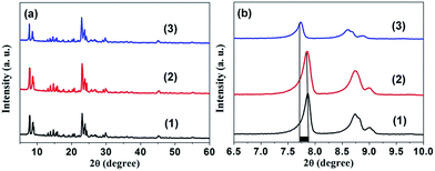 | ||
| Fig. 1 (a) XRD patterns. (b) Enlarged XRD patterns between 2θ = 6.5 and 10.0 degree for ZSM-5 (1), ion-exchanged Mn/ZSM-5 (2), and hydrothermal 2% Mn-ZSM-5 (3). | ||
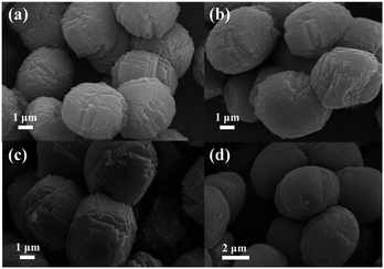
Typical SEM images of the as-synthesized samples are displayed in Fig. 2. From the panoramic view, the as-prepared ZSM-5 products consist of irregular blocks that form the final micro-ellipse spheres. The parental ZSM-5 is uniform with long and short axes ranging from 3 to 5 μm (Fig. 2a). Amazingly, the final microstructures show no differences between their stacked-block ellipses, even when Mn2+ ions break into the reaction solution.
However, as clearly observed in Fig. 2b–d, the sizes of the Mn-ZSM-5 samples become larger (4–6 μm) with the content of Mn-doping, as a result of the growth acceleration of ZSM-5 via impurities (Mn ions).41
The compositional data of the as prepared P0–P1 samples are shown in Table 1. As the SiO2/Al2O3 ratio increases, the Mn/(Si + Mn) atom ratio increases and the theoretical doping increases, indicating that Mnx+ substitutes Al3+ into the ZSM-5 lattice and thus drives the formation of a stable MFI structure. Table 1 also presents the BET surface area and pore volume; the pore volume increases even when the surface area decreases, as Mn ions come into the MFI-structured ZSM-5. As shown in Fig. 3, the element mapping of Si, Al, O and Mn in the microstructures demonstrates that all of these elements are distributed throughout the ZSM-5 micro-ellipse spheres (Fig. S1†). This confirms the occurrence of homogeneous distributions of Si, Al, O and Mn, which is consistent with the XRD results.
| Sample | SiO2/Al2O3 ratios | Mn/(Si + Mn) (mol%) | Surface area (m2 g−1) | Pore volume (mL g−1) |
|---|---|---|---|---|
| P0 | 41 | 0 | 409.332 | 0.179 |
| P1 | 42 | 0.38 | 355.151 | 0.194 |
| P2 | 43 | 0.87 | 401.455 | 0.271 |
| P3 | 50 | 1.31 | 406.267 | 0.277 |
| P4 | 68 | 2.45 | 360.351 | 0.227 |
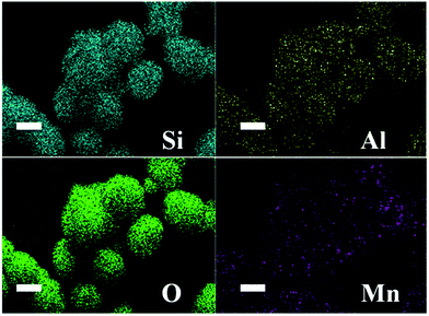 | ||
| Fig. 3 EDS mapping images of P3 micro-ellipse spheres: Si (blue-green), Al (yellow), O (green) and Mn (purple). | ||
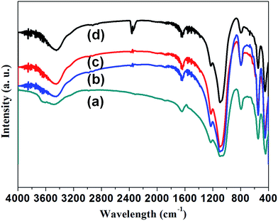
FTIR analysis was also carried out to investigate the influence of the impurity doping on the formation of ZSM-5 crystals. Fig. 4 presents the infrared (IR) spectrum of ZSM-5 and Mn-ZSM-5 zeolites. The typical vibration peaks represent the MFI-type zeolite material, and the well-defined peaks reveal the good crystalline properties of these materials. The absorbance bands at about 3450 cm−1 and 1630 cm−1 belong to the stretching and bending vibrations of silanol groups (Si–OH) or adsorbed H2O. These absorption vibration peaks at 450 cm−1, 540 cm−1 and 800 cm−1 are typical peaks attributed to the Si–O bending vibration, pentasil framework vibration and Si–O–Si symmetric vibration, respectively. Clearly, the peak of the pentasil framework vibration is retained well, even when Mn ions break into the MFI structure. In other words, the impurities move into the pentasil framework. The vibration absorption peaks at 1090 cm−1 and 1220 cm−1 are assigned to internal and external T–O (T = Si, Al) asymmetric stretching. As can be obviously observed, the peak area becomes larger with the incorporation of Mn ions, leading to the distortion of [TO] units as Mn ions with a larger radius substitute Si atoms (with a smaller radius), confirming the formation of Si–O–Mn bonds in the zeolite frameworks.42,43 Overall, it can be inferred that the ZSM-5 structures were in situ functionalized with manganese ions.
XPS measurements were used to evaluate the surface structure and chemical states of the as-prepared catalysts. Fig. 5a shows the XPS spectrum of pure ZSM-5 (P0) and Mn-ZSM-5 (P3) as typical examples. The peaks located at 75, 103, 532, and 642 eV are assigned to the characteristic peaks of Al 2p, Si 2p, O 1s, and Mn 2p, respectively.44,45 As expected, all of the above sharp peaks verify the abundant existence of Al, Si, O and Mn elements on the surface of Mn-ZSM-5. The strong peaks at 641.95 eV and 654.1 eV (Fig. 5e) demonstrate that Mn existed predominantly in the Mn4+ form, which has a strong oxidizing ability in the structure of the ZSM-5 micro-ellipse spheres. Indeed, the content of Mn4+ (Mn/(Si + Mn), mol%) was calculated to be 1.37%, close to the ICP data. Notably, in Fig. 5b–d (black lines), the Al 2p, Si 2p and O 1s peaks of the Mn-ZSM-5 microstructures showed negative shifts compared to those of pure ZSM-5 (red lines), which may be caused by the transfer of electrons from Mn to Al during the formation of Mn-ZSM-5.46,47 The downshift is directly related to the adsorption energies of the reactants on the catalyst as well as their activation barriers, which may contribute to the improvement of the catalytic activity.48,49 Furthermore, in the O 1s XPS spectrum (Fig. 5c), the BE peak located at 532.32 eV can be indexed to the lattice oxygen of ZSM-5.50 It is obvious that the shoulder width of the main BE peak (black line) becomes broader than that in the pure ZSM-5 (red line), indicating a better capacity for oxygen storage attributed to defective oxygen regions or adsorbed oxygen, which is also related to the activity of the oxidation reaction.51–54
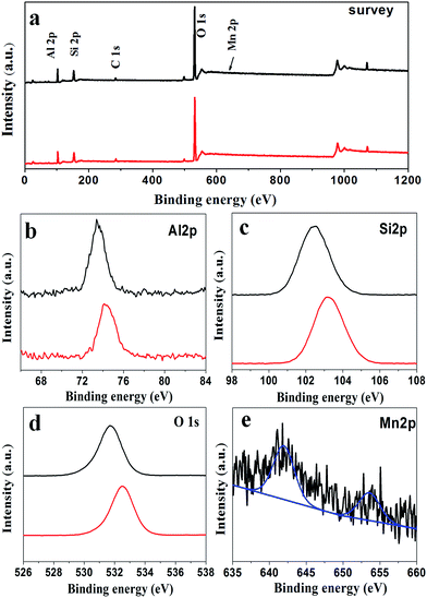 | ||
| Fig. 5 Representative XPS spectra of the P0 (red line) and P3 (black line) samples: (a) survey, (b) Al 2p, (c) Si 2p, (d) O 1s and (e) Mn 2p. | ||
3.2 Catalytic activity of Mn-containing ZSM-5 catalysts for the oxidation of cyclohexane with H2O2
Mn-framework-substituted molecular sieves have been found to be active in the catalytic oxidation of cyclohexane into cyclohexanone and cyclohexanol. Here, the cyclohexane oxidation reaction was selected to evaluate the catalytic properties of our prepared samples. Fig. 6 displays the catalytic activities of the Mn-doped ZSM-5 samples. Under such mild evaluation conditions (reaction temperature of 70 °C, reaction time of 6 hours), it can be seen that Mn-ZSM-5 (P1–P4) exhibit certain activity. Cyclohexane conversions (Ccyclohexane, mol%) of 21.21%, 20.72%, 30.66% and 19.53% were obtained, with selectivities to cyclohexanone and cyclohexanol (SKA, mol%) of 96.26%, 94.11%, 97.41% and 97.27%, respectively. In contrast, the parental ZSM-5 showed little catalytic activity (not shown in Fig. 6). The Mn4+ species in Mn-ZSM-5 are generally regarded as highly catalytically active centers,21,55,56 so it can be deduced that the formation of cyclohexanol and cyclohexanone should occur over Mn species from cyclohexane. Additionally, the EDS-mapping (Fig. 3) shows a good distribution of Mn atoms. Furthermore, the improved capacity for oxygen storage, attributed to the defective oxygen regions formed when Mn4+ substitutes Al3+ in the final ZSM-5 structures, is another important parameter for the higher conversion and selectivity of the cyclohexanol oxidation reaction. Notably, no other by-products (such as cyclohexyl peroxide, mono- and/or di-carboxylic acids and esters) were detected under such mild reaction conditions, which was confirmed by the gas chromatogram (GC) curve (Fig. S3†). Above all, the microporous structures of ZSM-5 function as nano-reactors for the catalytic reaction of cyclohexane, causing cyclohexane to be in full contact with H2O2. Once the catalytic centers (for example Mn4+ ions) are introduced into the microstructures, an effective reaction inevitably occurs. In addition, there are no diffusion limitations for cyclohexanone and cyclohexanol, which can travel efficiently through the ZSM-5 pores to avoid “over-oxidation”.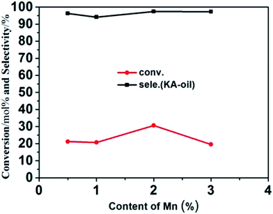 | ||
| Fig. 6 Conversion and selectivity of the catalytic oxidation of cyclohexane over as-prepared Mn-ZSM-5 with different doping content: 0.5%, 1%, 2%, 3%. | ||
3.3 Recycling studies
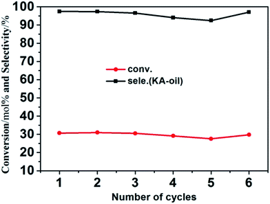
To demonstrate the cycling stability of the as-prepared Mn-ZSM-5 micro-ellipse spheres, recycling catalytic tests were performed 6 times. The catalyst recycling experiments were carried out with repeated uses of Mn-ZSM-5 at 70 °C for 6 hours using H2O2 as an oxidant. It can be seen from Fig. 7 that the conversion of cyclohexane and selectivity of KA oil remains above 20% and 92% for Mn-doped ZSM-5. ICP measurements were made (Table S1†) for both the reaction mixture and the used catalysts, combined with EDS mapping (Fig. S2†), and no leaching of manganese from Mn-ZSM-5 was found. This further confirms that Mn4+ successfully substitutes Al3+ in the inner-structure of ZSM-5 during the one-step hydrothermal synthesis. Amazingly, the catalytic activity decreased a little when the catalyst was in its fourth and fifth usage cycles, but before the sixth cycle, the catalyst was calcined at 550 °C for 6 hours and then performed almost as well as it did during the first cycle. To illustrate this phenomenon, FTIR measurements were made for the P3 sample after 5 cycles, without and with calcination, as shown in Fig. S4.† Clearly, a new peak at 2375 cm−1 (Fig. S4a†) can be observed, which is attributed to the ν(CN) stretching frequencies of the adsorption complexes associated with the bridging hydroxyls on Mn-ZSM-5.57 These adsorption complexes lead to the occlusion of catalytically active sites and finally, a decrease in the catalytic effect. Fortunately, Mn-ZSM-5 was easily refreshed via calcination and showed excellent catalytic activity (Fig. S4b†). Moreover, the characteristic peaks of Mn-ZSM-5 were maintained, even after several cycles, which further confirms the stability and recyclability of Mn-ZSM-5 for the oxidation of cyclohexane with H2O2 in the acetonitrile system.4 Conclusions
In summary, a series of designed ZSM-5 zeolites functionalized in situ with Mn was obtained via a one-pot hydrothermal approach, followed by calcination to remove TPAOH, the structure directing agent. The composition and morphology could be easily controlled even with the use of different amounts of dopant. Preliminary catalytic tests of the Mn-ZSM-5 materials demonstrated that the as-prepared products are promising catalysts for cyclohexane oxidation, especially the 2% Mn4+ doped ZSM-5 (P3), which shows a high catalytic ability with a conversion 30.66% and selectivity of KA oil of 97.41% for cyclohexane oxidation. These results may be a primary step towards understanding and designing manganese-doped zeolites with desirable morphologies and sizes, to enlarge their applications in catalytic fields.Conflicts of interest
There are no conflicts to declare.Acknowledgements
This work was supported by the National Science Fund for Distinguished Young Scholars (Grant No. 51325201); Natural Science Youth Fund (Grant No. 51502051) and by Key Laboratory of Micro-systems and Micro-structures Manufacturing of Ministry of Education, Harbin Institute of Technology (Grant No. 2015KM004).Notes and references
- A. Ebadi, N. Safsri and M. H. Peyrovi, Appl. Catal., A, 2007, 321, 135–139 CrossRef CAS.
- U. Schuchardt, W. A. Carvalho and E. V. Spinacé, Synlett, 1993, 10, 713–718 CrossRef.
- Y. Xiao, J. Liu, K. Xie, W. Wang and Y. Fang, Mol. Catal., 2017, 431, 1–8 CrossRef CAS.
- N. V. Maksimchuk, K. A. Kovalenko, V. P. Fedin and O. A. Kholdeeva, Chem. Commun., 2012, 48, 6812–6814 RSC.
- H. X. Yuan, Q. H. Xia, H. J. Zhan, X. H. Lu and K. X. Su, Appl. Catal., A, 2006, 304, 178–184 CrossRef CAS.
- C. Shi, B. Zhu, M. Lin, J. Long and R. Wang, Catal. Today, 2011, 175, 398–403 CrossRef CAS.
- S. A. C. Carabineiro, L. M. D. R. S. Martins, M. Avalos-Borja, J. G. Buijnsters, A. J. L. Pombeiro and J. L. Figueiredo, Appl. Catal., A, 2013, 467, 279–290 CrossRef CAS.
- J. Zhou, X. F. Yang, Y. Q. Wang and W. J. Chen, Catal. Commun., 2014, 46, 228–233 CrossRef CAS.
- (a) X. Liu, M. Conte, M. Sankar, Q. He, D. M. Murphy, D. Morgan, R. L. Jenkins, D. Knight, K. Whiston, C. J. Kiely and G. J. Hutchings, Appl. Catal., A, 2015, 504, 373–380 CrossRef CAS; (b) P. Wu, P. Bai, Z. F. Yan and G. X. S. Zhao, Sci. Rep., 2016, 1–11, DOI:10.1038/srep18817.
- L. Li, Q. Yang, S. Chen, X. Hou, B. Liu, J. Lu and H. Jiang, Chem. Commun., 2017, 53, 10026–10029 RSC.
- G. Sankar, R. Raja and J. M. Thomas, Catal. Lett., 1998, 55, 15–23 CrossRef CAS.
- R. Raja, G. Sankar and J. M. Thomas, J. Am. Chem. Soc., 1999, 121, 119261 CrossRef.
- J. M. Thomas and R. Raja, Chem. Commun., 2001, 675–687 RSC.
- J. M. Thomas, R. Raja, G. Sankar and R. G. Bell, Acc. Chem. Res., 2001, 34, 191–200 CrossRef CAS PubMed.
- E. V. Spinace, H. O. Pastore and U. Schuchardt, J. Catal., 1995, 157, 631–635 CrossRef CAS.
- J. Wang, F. Y. Zhao, R. J. Liu and Y. Q. Hu, J. Mol. Catal. A: Chem., 2008, 279, 153–158 CrossRef CAS.
- P. Tian, Z. M. Liu, Z. B. Wu, L. Xu and Y. L. He, Catal. Today, 2004, 93–95, 735–742 CrossRef CAS.
- E. L. Pires, U. Arnold and U. Schuchardt, J. Mol. Catal. A: Chem., 2001, 169, 157–161 CrossRef CAS.
- I. Sokmen and F. Sevin, J. Colloid Interface Sci., 2003, 264, 208–211 CrossRef CAS PubMed.
- T. Sooknoi and J. Limtrakul, Appl. Catal., A, 2002, 233, 227–237 CrossRef CAS.
- G. B. Shul'pin, G. Süss-Fink and J. R. L. Smith, Tetrahedron, 1999, 55, 5345–5358 CrossRef.
- M. Rezaei, A. N. Chermahini and H. A. Dabbagh, Chem. Eng. J., 2017, 314, 515–525 CrossRef CAS.
- C. Dai, A. Zhang, M. Liu, L. Gu, X. W. Guo and C. S. Song, ACS Nano, 2016, 10, 7401–7408 CrossRef CAS PubMed.
- C. H. Christensen, I. Schmidt, A. Carlsson, K. Johannsen and K. Herbst, J. Am. Chem. Soc., 2005, 127, 8098–8102 CrossRef CAS PubMed.
- J. Mielby, J. O. Abildstrom, F. Wang, T. Kasama, C. Weidenthaler and S. Kegnaes, Angew. Chem., Int. Ed., 2014, 53, 12513–12516 CAS.
- A. Aziz and K. S. Kim, J. Hazard. Mater., 2017, 340, 351–359 CrossRef CAS PubMed.
- H. Huang, Q. Feng, G. Liu, Y. Zhan, M. Wu, H. Lu, Y. Shu and D. Y. C. Leung, Appl. Catal., B, 2017, 203, 870–878 CrossRef CAS.
- T. Selleri, I. Nova and E. Tronconi, Appl. Catal., B, 2017, 206, 471–478 CrossRef CAS.
- Q. Dai, W. Wang, X. Wang and G. Z. Lu, Appl. Catal., B, 2017, 203, 31–42 CrossRef CAS.
- J. Zecevic, A. M. J. Vander Eerden, H. Friedrich, P. E. de Jongh and K. P. de Jong, ACS Nano, 2013, 7, 3698–3705 CrossRef CAS PubMed.
- B. Qi, X. H. Lu, D. Zhou, Q. H. Xia, Z. R. Tang, S. Y. Fang, T. Pang and Y. L. Dong, J. Mol. Catal. A: Chem., 2010, 322, 73–79 CrossRef CAS.
- R. Zhao, D. Ji, G. M. Lv, G. Qian, L. Yan, X. L. Wang and J. S. Suo, Chem. Commun., 2004, 904–905 RSC.
- C. Knapp, A. Obuchi, J. O. Uchisawa, S. Kushiyama and P. Avila, Microporous Mesoporous Mater., 1999, 31, 23–31 CrossRef CAS.
- (a) E. Yuan, K. Zhang, G. Lu, Z. Mo and Z. C. Tang, J. Ind. Eng. Chem., 2016, 42, 142–148 CrossRef CAS; (b) X. Du, X. Wang, Y. Chen, X. Gao and L. Zhang, J. Ind. Eng. Chem., 2016, 36, 271–278 CrossRef CAS.
- Y. T. Meng, H. C. Genuino, C. H. Kuo, H. Huang, S. Y. Chen, L. C. Zhang, A. Rossi and S. L. Suib, J. Am. Chem. Soc., 2013, 135, 8594–8605 CrossRef CAS PubMed.
- F. T. Fan, Z. C. Feng and C. Li, Chem. Res., 2010, 43, 378–387 CrossRef CAS PubMed.
- W. B. Fan, R. G. Duan, T. Yokoi, P. Wu, Y. Kubota and T. Tatsumi, J. Am. Chem. Soc., 2008, 130, 10150–10164 CrossRef CAS PubMed.
- P. Granger and V. I. Parvulescu, Chem. Rev., 2011, 111, 3155–3207 CrossRef CAS PubMed.
- M. M. J. Treacy and J. B. Higgins, Collection of Simulated XRD Powder Patterns for Zeolites, Elsevier, 2001 Search PubMed.
- T. Wang, H. Zhang and Y. Yan, J. Solid State Chem., 2017, 251, 55–60 CrossRef CAS.
- X. Niu, H. Wei, W. Liu, S. Wang, J. Zhang and Y. Z. Yang, RSC Adv., 2015, 5, 33615–33622 RSC.
- Y. T. Meng, H. C. Genuino, C. H. Kuo, H. Huang, S. Y. Chen, L. C. Zhang, A. Rossi and S. L. Suib, J. Am. Chem. Soc., 2013, 135, 8594–8605 CrossRef CAS PubMed.
- G. Vitale, H. Molero, E. Hernandez, S. Aquino, V. Birss and P. Pereira-Almao, Appl. Catal., A, 2013, 452, 75–87 CrossRef CAS.
- C. C. Li, X. M. Yin, T. H. Wang and H. C. Zeng, Chem. Mater., 2009, 21, 4985 Search PubMed.
- L. Liu, X. J. Zhang, R. Y. Wang and J. Z. Liu, Superlattices Microstruct., 2014, 72, 219–229 CrossRef CAS.
- H. Guan, C. Chao, W. Kong, Z. Hu, Y. Zhao, S. Yuan and B. Zhang, J. Nanopart. Res., 2017, 19, 187–197 CrossRef.
- P. K. Sahoo, B. Panigrahy and D. Bahadur, RSC Adv., 2014, 4, 48563–48571 RSC.
- P. Zhang, R. Li, Y. Huang and Q. Chen, ACS Appl. Mater. Interfaces, 2014b, 6, 2671–2678 Search PubMed.
- M. Ahmadi, C. Cui, H. Mistry, P. Strasser and B. R. Cuenya, ACS Nano, 2015, 9, 10686–10694 CrossRef CAS PubMed.
- M. M. Rahman, S. B. Khan, M. Faisal, M. A. Rub, A. O. Al-Youbi and A. M. Asiri, Talanta, 2012, 99, 924–931 CrossRef CAS PubMed.
- X. Niu, H. Wei, K. Tang, W. Liu, G. Zhao and Y. Z. Yang, RSC Adv., 2015, 5, 66271–66277 RSC.
- W. Liu, X. F. Liu, L. J. Feng, J. X. Guo, A. R. Xie, S. P. Wang, J. C. Zhang and Y. Z. Yang, Nanoscale, 2014, 6, 10693–10700 RSC.
- X. Y. Zhang, J. J. Wei, H. X. Yang, X. F. Liu, W. Liu, C. Zhang and Y. Yang, Eur. J. Inorg. Chem., 2013, 25, 4443–4449 CrossRef.
- S. P. Wang, X. C. Zheng, X. Y. Wang, S. R. Wang, S. M. Zhang, L. H. Yu, W. P. Huang and S. H. Wu, Catal. Lett., 2005, 105, 163–168 CrossRef CAS.
- W. F. Hölderich, Stud. Surf. Sci. Catal., 1989, 49, 69–93 CrossRef.
- G. N. Vayssilov, Catal. Rev.: Sci. Eng., 1997, 39, 209–247 CAS.
- J. Kotrla, L. Kubelková, C. C. Lee and R. J. Gorte, J. Phys. Chem. B, 1998, 102, 1437–1443 CrossRef CAS.
Footnote |
| † Electronic supplementary information (ESI) available: SEM of P3 sample before and after catalysis, EDS mapping of Mn-ZSM-5 after 6 cycles, ICP results of catalytic reaction mixture and solid catalyst. GC curve of the catalytic products. FTIR spectra of the P3 sample after five cycles with different treatments. See DOI: 10.1039/c7ra10771d |
| This journal is © The Royal Society of Chemistry 2017 |

