
 Open Access Article
 This Open Access Article is licensed under a
 Creative Commons Attribution 3.0 Unported Licence
Hierarchical carbon nanotube hybrid films for high-performance all-solid-state supercapacitors†
Susheng Zhouab,
Sha Zengb,
Silan Zhangb,
Jian Qiaob,
Jiangtao Di *b,
Minghai Chen*b,
Ning Liu*a and
Qingwen Lib
*b,
Minghai Chen*b,
Ning Liu*a and
Qingwen Lib
aSchool of Materials Science and Engineering, Hefei University of Technology, Hefei 230009, People's Republic of China. E-mail: liuning@hfut.edu.cn
bSuzhou Institute of Nano-Tech and Nano-Bionics, Chinese Academy of Sciences, Suzhou 215123, People's Republic of China. E-mail: jtdi2009@sinano.ac.cn; mhchen2008@sinano.ac.cn
First published on 8th November 2017
Abstract
Electrodes that have high electrical conductivity, large ion-accessible area and good mechanical robustness are highly needed for developing high-performance flexible supercapacitors. Herein, we report the preparation of a carbon nanotube (CNT) hybrid film consisting of large-diameter multi-walled carbon nanotubes (MWCNTs) and small-diameter single-walled carbon nanotubes (SWCNTs) and its application as an electrode for flexible supercapacitors. In the hybrid film, MWCNTs provide a macroporous and robust scaffold while SWCNTs bridge MWCNTs and improve the film's strength and electrical conductivity. Resulting from such a hierarchical structure that could facilitate ion transportation inside of the electrode, the specific capacitance of SWCNTs loaded in hybrid films was increased by about 273% when compared with that of SWCNT films. A thin layer of polyaniline was electrochemically deposited on the hybrid film, forming a composite film with good structural flexibility and high capacitance. Solid-state symmetric supercapacitors assembled using such a composite film electrode showed good rate performance and high cycling stability.
1. Introduction
Supercapacitors store energy by utilizing electrostatic double-layer capacitance, electrochemical pseudocapacitance or a combination of the above mentioned two types of capacitance.1,2 They bridge the gap between electrolytic capacitors and rechargeable batteries3,4 and are capable of fast charging and discharging,5,6 which is highly needed for diverse applications.7The emergence of carbon nanotubes (CNTs) has paved the way for developing high-performance supercapacitors, even though activated carbon is still the dominating material used in supercapacitors. Carbon nanotubes commonly have a large surface area, high electrical conductivity, and novel stability, which result in high double layer capacitance when they are utilized as active materials in supercapacitors.8 They can also be used as conducting additives to improve the rate performance of pseudocapacitance capacitors.9,10 More importantly, films of CNTs are mechanically strong, lightweight and flexible.11,12 They can be used as high-surface-area current collectors and electrodes of flexible supercapacitors for powering wearable electronics.13,14
The structures and surface properties15–18 of individual CNTs and the assembling structures19–26 of CNT films are closely related with the performance of supercapacitors. Till now, CNTs with various structures have been prepared. Generally, pristine single-walled carbon nanotube (SWCNTs) have higher electrostatic double-layer capacitances than multi-walled carbon nanotubes (MWCNTs),15–18 which can be explained by the small diameters and high surface areas of SWCNTs. However, when assembled into a film, SWCNTs are commonly aggregated into big bundles, which makes the dense film hard for the diffusion of ions in aqueous electrolytes. This leads to the insufficient use of the large surface of SWCNTs for capacitance. On the other hand, large-diameter MWCNTs can form a film that is suitable of ion diffusion due to the formation of a porous structure. Disadvantages such as low electrical conductivities, low surface area, low mechanical strength have limited the utilization of MWCNT films for supercapacitor electrodes.
Herein, we report the perparation of a hybrid film consisting of large-diameter MWCNTs and small-diameter SWCNTs. This film has a hierarchical structure. When utilized as an electrode for supercapacitor, it could facilitate the full use of surface area of CNTs for capacitance contribution, achieving high-performance supercapacitors. We utilized the widely-used vacuum filtration method for preparing hybrid films, which allows us to readily mixing two types of CNTs that vary largely in diameters into a hybrid film. The hybrid film was further electrochemically deposited with polyaniline and solid-state symmetric supercapacitors assembled using such composite film electrode showed good rate performance and high cycling stability.
2. Experimental section
2.1 Materials
Large-diameter multi-walled carbon nanotubes (MWCNTs, diameter is about 50 nm (see from Fig. S2a†), the height of vertically aligned CNT is about 1 mm (see from Fig. S3†)) synthetized by a floating catalyst chemical vapor deposition (CVD) method and more details could see from our previous work.27 Single-walled carbon nanotubes (SWCNTs, d < 2 nm, l > 1 μm) were purchased from OCSIAL Co., Ltd. After dispersing in water, its bundle diameter is no more than 5 nm (Fig. S2b†). Raman spectra show that the intensity ratios of G band over D band are 20 for SWCNTs and 1.5 for MWCNTs, respectively (Fig. 2d). Polyvinylpyrrolidone (PVP), sodium dodecyl benzene sulfonate (SDBS), sulphuric acid (H2SO4), potassium hydrate (KOH), aniline, acetone and absolute ethyl alcohol were of analytical grade and purchased from Sinopharm Chemical Reagent Co., Ltd. (Shanghai, PRC). Konjac glucomannan (KGM) was purchased from Hefei Bomei Biotechnology Co., Ltd. (Hefei, PRC). Cellulose microporous filtering film with 1.2 μm diameter pore was purchased from Hangzhou ANOW Microfiltration Co., Ltd. Deionized water was used as the solvent throughout the entire experiment.2.2 Synthesis
Simplified sketch map of preparation process of supercapacitor is shown in Fig. S1.† Which include preparation of CNT suspension, flexible CNT films, flexible CNT/PANI films, and all-solid-state supercapacitor.A MWCNT suspension having a concentration of 0.5 wt% was obtained by a high-pressure homogenization method. Two and a half grams PVP was dissolved in 495 g deionized water, and then 2.5 g MWCNT was added into the solution. After intensive stirring, the mixed solution was homogenized by bead ball-milling at a pressure of 1000 bar.
2.3 Materials characterization
The thickness and mass of CNT film was obtained from micrometer caliper and high-precision electronic balance respectively. The microstructures of the samples were observed by scanning electron microscopy (SEM) (Quanta 400FEG, FEI) and transmission electron microscope (TEM) (Tecnai G2 F20 S-Twin, FEI). The sheet resistances of CNT film electrodes were tested by four-probe equipment (Model ST-2258A, Suzhou Jingge Electronic Co., Ltd., China). The mechanical tensile strength was measured by a universal testing machine (Instron 3365) with a load cell of 10 N and test samples conform to 3 mm × 20 mm rectangle pattern. The Raman spectrum was measured by a laser confocal Raman microscopy (LabRAM HR, HORIBA Jobin–Yvon). Thermo-gravimetric analysis was executed by thermogravimetry (TG 209F1, NETZSCH, Germany). The raw SWCNTs and MWCNTs powders have purities of 82 wt% and 93 wt%, respectively and the impurities are mainly amorphous carbon, catalyst and catalyst support. TG of 30 wt% hybrid CNT film (Fig. S8†) indicate dispersant content is no more than 20 wt% and the residual impurity mass was about 5 wt%. Cyclic voltammetry (CV) conducted on a hybrid film containing 30 wt% SWCNTs that was not electrochemically oxidized show a box feature that is consistent with the electrical double layer capacitance (Fig. S15†). Although after electrochemical oxidation, the CV curves becomes non-box shaped (Fig. 3a) due to the introduction of oxygen containing functional groups on nanotube. These comparison results indicated that the impurity almost had no obvious effect on the capacitance behavior.2.4 Electrochemical measurement
3. Results and discussion
3.1 Hierarchical structure of the hybrid film
Fig. 1a schematically shows the hierarchical structure of our CNT hybrid films. Due to rigidity difference, large-diameter MWCNTs form a loose and relatively rigid scaffold with abundant pores, separating small-diameter SWCNTs from aggregating into a densely packed film. This hierarchical structure provides free pathways for facilitating ion accessibility to CNT surface (Fig. 1b), making the full use of nanotube surface for capacitance contribution. Fig. 1c shows the scanning electron microscopy (SEM) image of presently used pristine MWCNTs. These nanotubes have an average diameter of 50 nm with 30 graphitic walls and lengths over tens of μm (Fig. S2a and S3†). Due to the relatively lager diameter, these thick and rigid nanotubes were separated individually and remained straight even after vacuum deposition. Fig. 1d shows the SEM image obtained at the same magnification as Fig. 1c for a film of SWCNTs bundles that have a small diameter of only 5 nm (Fig. S2†). This film was densely packed and very small pores in tens of nanometer scale were observed. Vacuum filtration of a mixture of 30 wt% SWCNTs and 70 wt% MWCNTs resulted in a hybrid film that has a hierarchical structure as shown by the SEM image of Fig. 1e. By using different amount ratio of MWCNT/SWCNT, we prepared a series of hybrid films (Fig. S4†). When the weight percent of SWCNTs was less than 30 wt%, SWCNT bundles bridged between MWCNT and macropores were still distinguishable (Fig. S4b†). Further increasing the amount of SWCNTs led to the dense fill of pores between MWCNTs (Fig. S4c†).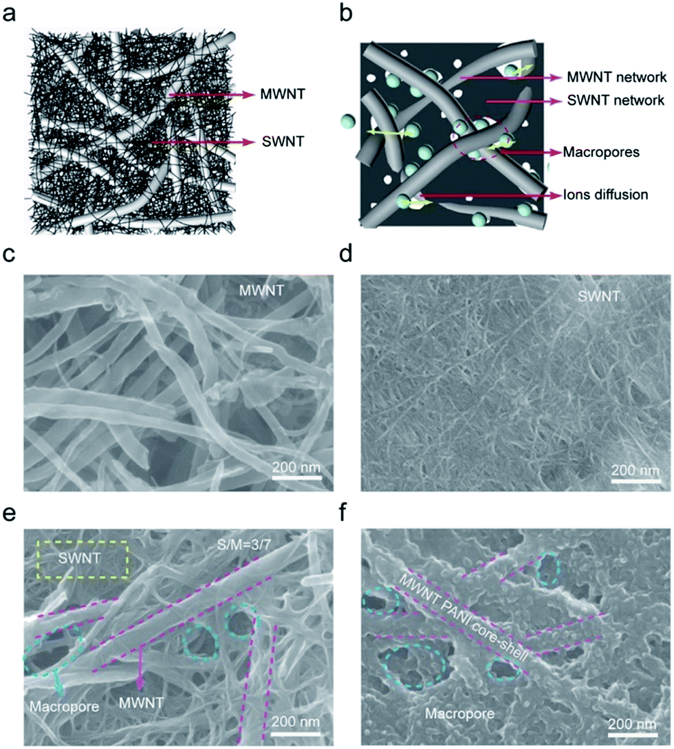 | ||
| Fig. 1 (a) Schematic showing the hierarchical structure of the hybrid film consisting of MWCNTs and SWCNTs, where large-diameter MWCNTs penetrate between small-diameter SWCNTs, facilitating ion diffusion in a supercapacitor electrode (b). (c) SEM image of a MWCNT film with abundant interior pores. (d) SEM image of a SWCNT film, showing that SWCNTs were densely packed in the film. (e) SEM image of a CNT film consisting of 30 wt% SWCNTs and 70 wt% MWCNTs. (f) SEM image of a PANI-coated CNT hybrid film. | ||
3.2 Basic properties of hybrid CNT films
Mechanical robustness is essential when CNT films are used as electrodes for flexible supercapacitors. The tensile strength (Fig. 2a) of the pristine MWCNT films is only 2 MPa and these films were easily break when bent. Thus, they did not meet the requirements. On the other hand, the SWCNT showed a tensile strength of about 52 MPa and very good structure flexibility. The tensile strength of hybrid films increased with increasing the weight percent of SWCNTs and when over 40 wt%, the hybrid films showed comparable tensile strengths with SWCNT films but much improved failure strain. A hybrid film having 30 wt% SWCNTs showed a tensile strength of 27 MPa and a failure strain of 3.6%. These mechanical properties enabled the folding of such hybrid film into an intact self-supporting origami crane (Fig. 2b). The increasing in mechanical strength should be ascribed to stronger van der Waals' force and more entanglement sites among SWCNTs. The electrical conductivity of MWCNT film (Fig. S7†) is only 1333 S m−1 while that of SWCNT film is up to 27![[thin space (1/6-em)]](https://www.rsc.org/images/entities/char_2009.gif) 027 S m−1. It is worth to mention the electrical conductivity of 30 wt% hybrid CNT film (10000 S m−1) reaches to the same order of magnitude of SWCNT film.
027 S m−1. It is worth to mention the electrical conductivity of 30 wt% hybrid CNT film (10000 S m−1) reaches to the same order of magnitude of SWCNT film.
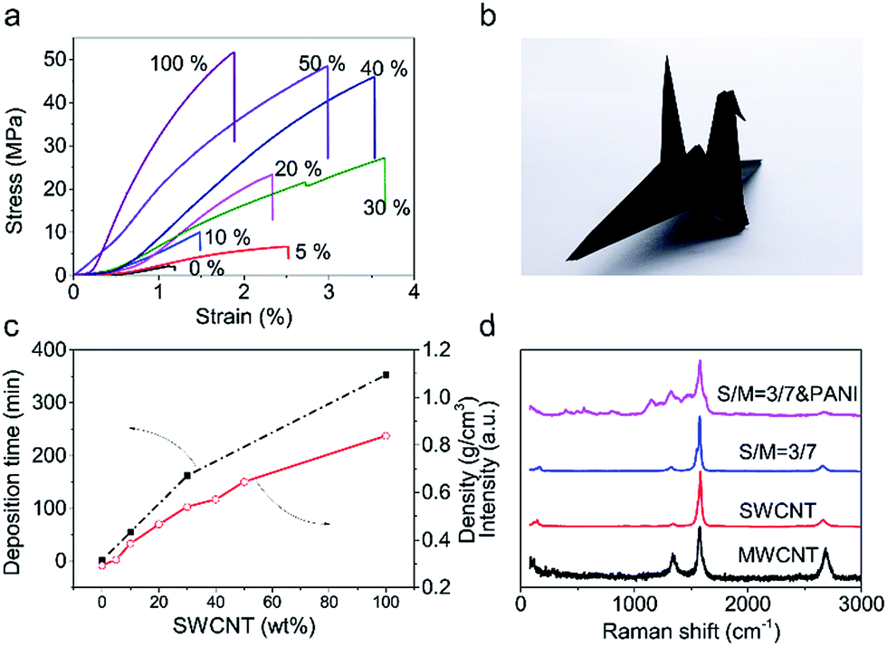 | ||
| Fig. 2 Basic properties of hybrid CNT films: (a) stress–strain curves of MWCNT films, hybrid CNT films, and SWCNT films. (b) An origami crane prepared using a CNT film having 30 wt% SWCNTs and 70 wt% MWCNTs, indicating the novel structure foldability of such hybrid films. (c) Consumption time in vacuum filtration process (left) and density of hybrid CNT films (right) as a function of weight percent of SWCNTs. (d) Raman spectra of MWCNT, SWCNT, hybrid CNT, and PANI-coated CNT films. | ||
Depositing time (Fig. 2c) assumed for a given weight of CNT film show huge difference with different SWCNT proportion. A MWCNT film needs only 2 min to complete filtration progress while a SWCNT film needs 365 min. So it is clearly to see that due to MWCNT skeleton has reserved abundant macropores, the preparation efficiency has greatly improved. The existence of massive macropores should reduce density of CNT film. The variation trend of density (Fig. 2c) confirms the variation trend of depositing time.
3.3 Electrochemical characterizations of pure hybrid CNT films
Fig. 3 shows the electrochemical results of the investigated samples of CNT films obtained in 6 M KOH electrolyte using investigated samples as the working electrode, SCE as the reference electrode and a Pt wire as counter electrode, respectively. All the samples showed non-box shaped cyclic voltammetry (CV) curves (Fig. 3a). This could be explained by the introduction of oxygen containing functional groups on nanotube surface during hydrophilic treatments,28 which contributed pseudocapacitance. Fig. 3b shows the GCD curves obtained at a charging/discharging current density of 1 mA cm−2 for the investigated samples. Based on the capacitance calculated from the GCD curves, the SWCNT films showed the highest capacitance (58.4 F g−1), the MWCNT films showed the lowest capacitance (21.2 F g−1), and the specific capacitance of hybrid films calculated based on the film mass were in between (Fig. S9†).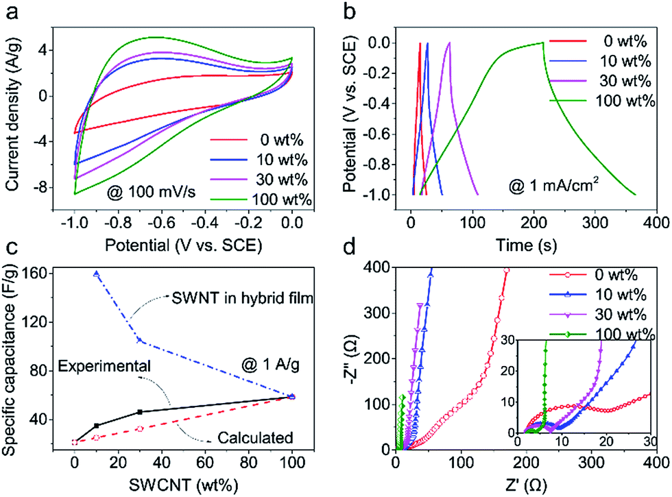 | ||
| Fig. 3 Electrochemical characterizations of pure hybrid CNT films. (a) CV curves obtained at 100 mV s−1, (b) GCD curves at 1 mA cm−2, and (c) specific capacitance calculated based on the weights of hybrid CNT films and SWCNTs in hybrid CNT films as a function of SWCNT weight percent. (d) Nyquist plots for MWCNT films and CNT films having different amount of SWCNTs. | ||
For the hybrid films, the specific capacitance increased considerably with increasing the weight percent of SWCNTs compared with that of pristine MWCNT films. For example, the specific capacitance of the hybrid film having 30 wt% SWCNTs is 78.9%, comparable with that for SWCNT films but 2.2 times that for MWCNT films. The capacitance of a hybrid CNT film (Ch) is the sum of capacitances of SWCNTs (Cs) and MWCNTs (Cm), which could be calculated from the equation, Ch = Cs × α + Cm × (1 − α), where α is the proportion of SWCNTs. Assuming that the specific capacitances of MWCNT and SWCNT films are irrelevant with material mass, we calculated the specific capacitance for the hybrid films (Fig. 3c). The calculated results were much lower than the experimental results, which indicates more capacitance contribution from SWCNTs than expected. Moreover, a small content of SWCNT addition (10 wt%) leads to a sharp increase of specific capacitance compared with MWCNT films. The slope of specific capacitance versus SWCNT weight percent decreased when over 10 wt% SWCNTs. This phenomenon is closely related to utilization efficiency of SWCNT surface. In a low SWCNT content, there is nearly no dense SWCNT region and there is abundant space among SWCNTs, thus lead to a high utilization efficiency of SWCNTs. However, with SWCNT increasing, there appear some dense SWCNT regions on the region lack of MWCNT and lead to a low utilization efficiency of SWCNTs especially for SWCNT film losing skeleton effect of MWCNT totally.
We further calculated the specific capacitance of SWCNTs in hybrid films by subtracting the MWCNT capacitance from the total capacitance of hybrid films (see the calculation details in ESI†). The calculated results were plotted in Fig. 3c. Surprisingly, SWCNTs in hybrid films showed much higher specific capacitance than pure SWCNT films. For example, the SWCNTs that accounted for 10 wt% in the hybrid film showed a specific capacitance of 159.2 F g−1, 2.7 times the specific capacitance of pure SWCNT films (58.4 F g−1). The SWCNTs that accounted for 30 wt% in the hybrid film showed a specific capacitance of 104.2 F g−1, 1.8 times the specific capacitance of pure SWCNT films. This comparison result indicated the synergistic effect between MWCNTs and SWCNTs in the hybrid film on improving the utilization of nanotube surface for capacitance.
There appears semi-circle in high frequency region of the Nyquist plots (Fig. 3d), which might be due to pseudocapacitance characteristic of CNT film after hydrophilic treatment. Thus, the capacitance of these CNT film is a combination of pseudocapacitance and double layer capacitance. Besides, the charge-transfer resistance (Rp) decreases with SWCNT increasing. The variation trend of electrical conductivity tested by four point probe is consisted with EIS plots. All of these indicate that SWCNTs bridge MWCNTs and improve electrical conductivity.
3.4 Electrochemical test of hybrid CNT/PANI films
A thin layer of polyaniline (PANI) was electrochemically deposited on the hybrid film having 30 wt% SWCNTs to further increase capacitance. Most intuitive difference before and after depositing PANI is color change (Fig. S10†) on its surface. Color on the surface of CNT film transforms form black to mixed color of blue and purple. Fig. 1f and S5† show the SEM image of the CNT/PANI film, which indicates that PANI was conformally coated on the hybrid film. The results of Raman spectra (Fig. 2d) indicate the success of deposition of PANI. The characteristic peaks at 414 cm−1, 574 cm−1, and 809 cm−1 can be assigned to C–N–C out of plane deformation mode, the deformation mode of the protonated amine groups, C–H motion out of plane of PANI, respectively.29 The FTIR spectra (Fourier Transform infrared spectroscopy) was shown in Fig. S11.† Compared to the characteristic band (1569, 1492, 1298 and 1120 cm−1) of PANI in previous work.30 The characteristic band of PANI in our CNT/PANI composite shifted to lower wavenumber direction. In Fig. S11,† the bands at 1542 and 1457 cm−1 are assigned to C![[double bond, length as m-dash]](https://www.rsc.org/images/entities/char_e001.gif) C stretching vibrations of quinoid and benzenoid rings respectively. The bands at 1269, and 1104 cm−1 originate from C–N and CN stretching vibration, respectively. These results provide evidence that PANI has been successfully deposited on the CNT film. XPS (X-ray photoelectron spectroscopy) (Fig. S12†) indicate that CNT/PANI film had a high N content (7.3 at%). EDX (Energy Dispersive X-ray) elemental mapping (Fig. S13†) indicate that N element was uniformly distributed.
C stretching vibrations of quinoid and benzenoid rings respectively. The bands at 1269, and 1104 cm−1 originate from C–N and CN stretching vibration, respectively. These results provide evidence that PANI has been successfully deposited on the CNT film. XPS (X-ray photoelectron spectroscopy) (Fig. S12†) indicate that CNT/PANI film had a high N content (7.3 at%). EDX (Energy Dispersive X-ray) elemental mapping (Fig. S13†) indicate that N element was uniformly distributed.
Two pairs of redox peaks of PANI (ascribed to the transitions of PANI between leucoemeraldine to emeraldine and emeraldine to pernigranilin)31 are shown in CV curves (Fig. 4a). Besides, there appears charge/discharge platform in GCD curves (Fig. 4b). All of these shape changes compared to pure CNT film indicates CNT/PANI film has a pseudocapacitance.
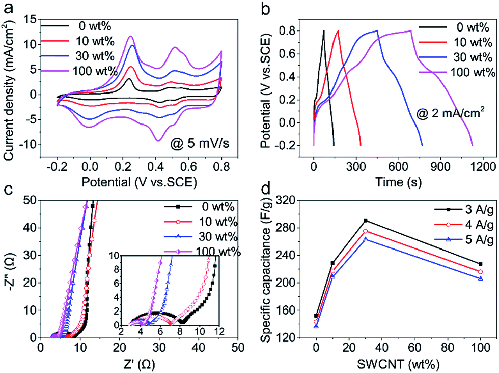 | ||
| Fig. 4 Electrochemical test of hybrid CNT/PANI films in three-electrode system: (a) CV curves at 5 mV s−1. (b) GCD curves at 2 mA cm−2. (c) Nyquist plots with a frequency range of 100 kHz to 0.01 Hz. (d) Specific capacitance of CNT/PANI films at different current density characteristic. | ||
In Nyquist plots (Fig. 4c), the Rp of 30 wt% hybrid CNT film is 1.9 Ω and is very close to that of SWCNT (1.2 Ω). In the low-frequency region of Nyquist plots, the slope of straight line decreases with SWCNT increasing, which might be due to dense SWCNT net blocks up some macro-pores with SWCNT increasing and thus hinders rapid diffusion of ions and deteriorates capacitive performance.32,33 In consideration of different PANI deposition mass, here the mass specific capacitance is shown in Fig. 4d. The capacitance of 30 wt% hybrid CNT/PANI film (290.6 F g−1) is 1.3 times SWCNT/PANI film (227.4 F g−1) and 1.9 times MWCNT/PANI film (152.3 F g−1) at 3 A g−1. This phenomenon is due to hierarchical structure of hybrid CNT film with synergistic effect of SWCNT and MWCNT and high utilization efficiency of SWCNTs. Excellent performance of 30 wt% hybrid CNT/PANI film consistent with the results for hybrid CNT films. Besides, all CNT film show a good rate capability and the capacitance variation range was no more than 14 F g−1 within a current density variation range of 1 A g−1.
3.5 Electrochemical test of all-solid-state supercapacitors
We further assembled a symmetrical flexible all-solid-state supercapacitor using a pair of 30 wt% hybrid CNT/PANI film as electrode. Fig. 5a schematically shows the device structure. There are not pronounced redox peaks in CV curves (Fig. 5b) and charge/discharge platform in GCD curves (Fig. 5c) as previous work reported.34,35 Rate capability of supercapacitor is shown in Fig. 5d. It possesses a high capacitance of 245.6 mF cm−2 at a small current density of 1 mA cm−2 and 158.8 mF cm−2 at a large current density of 10 mA cm−2. Metallic oxide usually have a very high capacity while perform badly in rate capability. Such as h-RuO2/MWCNT36 and G/SWCNT/Co3O4.37 Pure carbon materials performed well in rate capability but have a low specific capacitance. Such as G/SWCNT hybrids37 and G/DWCNT capacitor.38 The specific capacitance of G/DWCNT capacitor was just 10 mF cm−2, our SWCNT/MWCNT/PANI had a high capacitance of 245.6 mF cm−2 at 1 mA cm−2 and performed well in rate capability as shown in Fig. 5d. Fig. S16† shows that the supercapacitor had an energy density of 21.9 W h cm−2 at 400 W cm−2 and power density of 4000 W cm−2 with an energy density of 14.1 W h cm−2. When it comes to mass density, the supercapacitor had an energy density of 4.7 W h kg−1 at 177.1 W kg−1 and power density of 885.3 W kg−1 with an energy density of 3.1 W h kg−1 (Fig. S17†). Fig. 5f shows that coulombic efficiency remain around 100% throughout 11000 charging/discharging cycles, indicating a very good cyclic stability for our supercapacitors. In initial 1000 cycles, capacitance gradually drops from 100% (205.6 mF cm−2) to 83.3% (171.3 mF cm−2) and then keeps this value in next 7000 cycles. In last 3000 cycles, capacitance gradually increases to 91.5% (188.1 mF cm−2). Fig. 5e shows Nyquist plots of capacitor after different cycles. Rp is no more than 1 Ω for all of them. After 11000 cycles, the Rs increase from 9 Ω to 13 Ω, may resulting from electrolyte drying. Capacitance decay in initial 1000 cycles could be caused by PANI exfoliation. However, after a long period of charge/discharge cycles, KGM–H2SO4 gel electrolyte gradually permeates into CNT/PANI film, which leads to capacitance recovering in last 3000 cycles. In summary, after a long period of charge/discharge cycles (11000 cycles), this capacitor could still remain a high capacitance of 91.5% (188.1 mF cm−2) and this indicates it performs well in cyclic stability.
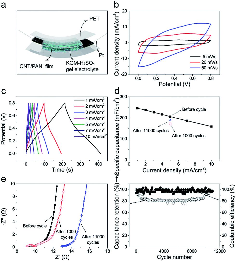 | ||
| Fig. 5 Electrochemical test of all-solid-state supercapacitors in a two-electrode system. (a) Schematic showing the structure of a symmetric supercapacitor using CNT/PANI films as electrodes and KGM–H2SO4 gel as electrolyte. (b) CV curves at different scanning rate. (c) GCD curves at different current density. (d) Specific capacitance at different current density. (e) Nyquist plot at different cycle number. (f) Cyclic performance of supercapacitor. | ||
4. Conclusions
In the hybrid film, MWCNTs provide as a macroporous and robust scaffold while SWCNTs bridge MWCNTs and improve the film strength and electrical conductivity. Resulting from such a hierarchical structure that could facilitate ion transportation in side of the electrode. Besides, electrochemical tests of pure CNT films indicate that the performance of hybrid CNT film is not the simple geometric addition and subtraction of MWCNT and SWCNT but a synergistic effect of MWCNT and SWCNT greatly related to utilization efficiency of SWCNT. The specific capacitance of SWCNTs loaded in 10 wt%, 30 wt% hybrid films was increased by about 273%, 178% respectively when compared with that of SWCNT films. Furthermore, after depositing PANI, the 30 wt% hybrid CNT/PANI film (290.6 F g−1 at 3 A g−1) even exceed SWCNT film (227 F g−1 at 3 A g−1) in mass specific capacitance. 30 wt% hybrid CNT film may be the better choice for flexible electrode after weighing deposition time, mechanical strength, electrical conductibility, coefficient of utilization of SWCNTs, and electrochemical properties. Finally, a symmetrical flexible all-solid-state supercapacitor was assembled by using a pair of 30 wt% hybrid CNT/PANI film as electrode. It performs well in rate capability (246.1 mF cm−2 at 1 mA cm−2, 158.8 mF cm−2 at 10 mA cm−2) and cyclic stability (maintaining capacitance of 91.5% after 11000 cycles at 5 mA cm−2).
Conflicts of interest
There are no conflicts to declare.Acknowledgements
The authors are thankful for financial support from the National Natural Science Foundation of China (21603264, 21473238), the CAS Pioneer Hundred Talents Program (J. Di), the National Key Research and Development Program of China (2016YFA0203301), the Key Research, Program of Frontier Science of the Chinese Academy of Sciences (QYZDB-SSW-SLH031), and the Fundamental Research Funds for the Central Universities (CUSF-DH-D-2015015).Notes and references
- Z. Yu, L. Tetard, L. Zhai and J. Thomas, Energy Environ. Sci., 2015, 8, 702–730 CAS.
- L. L. Zhang and X. S. Zhao, Chem. Soc. Rev., 2009, 38, 2520–2531 RSC.
- P. Simon, Y. Gogotsi and B. Dunn, Science, 2014, 343, 1210–1211 CrossRef CAS PubMed.
- A. Vlad, N. Singh, J. Rolland, S. Melinte, P. M. Ajayan and J. F. Gohy, Sci. Rep., 2014, 4, 4315 CrossRef CAS PubMed.
- K. Naoi, K. Kisu, E. Iwama, S. Nakashima, Y. Sakai, Y. Orikasa, P. Leone, N. Dupré, T. Brousse, P. Rozier, W. Naoi and P. Simon, Energy Environ. Sci., 2016, 9, 2143–2151 CAS.
- Q. Zhou, J. Chang, Y. Jiang, T. Wei, L. Sheng and Z. Fan, Electrochim. Acta, 2017, 251, 91 CrossRef CAS.
- A. Yu, I. Roes, A. Davies and Z. Chen, Appl. Phys. Lett., 2010, 96, 253105 CrossRef.
- E. Senokos, V. Reguero, L. Cabana, J. Palma, R. Marcilla and J. J. Vilatela, Adv. Mater. Technol., 2017, 2, 1600290 CrossRef.
- K. Wang, S. Luo, Y. Wu, X. He, F. Zhao, J. Wang, K. Jiang and S. Fan, Adv. Funct. Mater., 2013, 23, 846–853 CrossRef CAS.
- S. Zhang, M. Liu, F. Ma, F. Ye, H. Li, X. Zhang, Y. Hou, Y. Qiu, W. Li, J. Wang, J. Wang and Y. Zhang, J. Mater. Chem. A, 2015, 3, 18913–18919 CAS.
- H. Li, X. Lu, D. Yuan, J. Sun, F. Erden, F. Wang and C. He, J. Mater. Chem. C, 2017, 5, 8694 RSC.
- X. Xiao, X. Peng, H. Jin, T. Li, C. Zhang, B. Gao, B. Hu, K. Huo and J. Zhou, Adv. Mater., 2013, 25, 5091–5097 CrossRef CAS PubMed.
- T. Chen and L. Dai, J. Mater. Chem. A, 2014, 2, 10756 CAS.
- W. Li, X. Xu, C. Liu, M. C. Tekell, J. Ning, J. Guo, J. Zhang and D. Fan, Adv. Funct. Mater., 2017, 1702738, DOI:10.1002/adfm.201702738.
- M. Kaempgen, C. K. Chan, J. Ma, Y. Cui and G. Gruner, Nano Lett., 2009, 9, 1872–1876 CrossRef CAS PubMed.
- C. Zheng, W. Qian, C. Cui, Q. Zhang, Y. Jin, M. Zhao, P. Tan and F. Wei, Carbon, 2012, 50, 5167–5175 CrossRef CAS.
- M. Kaempgen, J. Ma, G. Gruner, G. Wee and S. G. Mhaisalkar, Appl. Phys. Lett., 2007, 90, 264104 CrossRef.
- J.-S. Ye, X. Liu, H. F. Cui, W.-D. Zhang, F.-S. Sheu and T. M. Lim, Electrochem. Commun., 2005, 7, 249–255 CrossRef CAS.
- F. Mirri, A. W. Ma, T. T. Hsu, N. Behabtu, S. L. Eichmann, C. C. Young, D. E. Tsentalovich and M. Pasquali, ACS Nano, 2012, 6, 9737–9744 CrossRef CAS PubMed.
- X. Zhao, B. T. Chu, B. Ballesteros, W. Wang, C. Johnston, J. M. Sykes and P. S. Grant, Nanotechnology, 2009, 20, 065605 CrossRef PubMed.
- S. R. Shin, R. Farzad, A. Tamayol, V. Manoharan, P. Mostafalu, Y. S. Zhang, M. Akbari, S. M. Jung, D. Kim, M. Comotto, N. Annabi, F. E. Al-Hazmi, M. R. Dokmeci and A. Khademhosseini, Adv. Mater., 2016, 28, 3280–3289 CrossRef CAS PubMed.
- P. Sun, Z. Deng, P. Yang, X. Yu, Y. Chen, Z. Liang, H. Meng, W. Xie, S. Tan and W. Mai, J. Mater. Chem. A, 2015, 3, 12076–12080 CAS.
- J. Zhang, D. Jiang and H.-X. Peng, Microporous Mesoporous Mater., 2014, 184, 127–133 CrossRef CAS.
- P.-X. Hou, B. Yu, Y. Su, C. Shi, L.-L. Zhang, C. Liu, S. Li, J.-H. Du and H.-M. Cheng, J. Mater. Chem. A, 2014, 2, 1159–1164 CAS.
- Q. Liu, M. Li, Y. Gu, Y. Zhang, S. Wang, Q. Li and Z. Zhang, Nanoscale, 2014, 6, 4338–4344 RSC.
- Y. Zhang, Z. Kang and T. Bessho, Nanotechnology, 2017, 28, 105607 CrossRef PubMed.
- H. Chen, M. Chen, Y. Zhang and Q. Li, Appl. Surf. Sci., 2015, 353, 651–661 CrossRef CAS.
- X. Cui, R. Lv, R. U. R. Sagar, C. Liu and Z. Zhang, Electrochim. Acta, 2015, 169, 342–350 CrossRef CAS.
- S. Zeng, H. Chen, F. Cai, Y. Kang, M. Chen and Q. Li, J. Mater. Chem. A, 2015, 3, 23864–23870 CAS.
- Q. Wang, Y. Wu, T. Li, D. Zhang, M. Miao and A. Zhang, J. Mater. Chem. A, 2016, 4, 3828–3834 CAS.
- X. Xiang, W. Zhang, Z. Yang, Y. Zhang, H. Zhang, H. Zhang, H. Guo, X. Zhang and Q. Li, RSC Adv., 2016, 6, 24946–24951 RSC.
- M. D. Stoller, S. J. Park, Y. W. Zhu, J. H. An and R. S. Ruoff, Nano Lett., 2008, 8, 3498–3502 CrossRef CAS PubMed.
- Y. Wang, Z. Q. Shi, Y. Huang, Y. F. Ma, C. Y. Wang, M. M. Chen and Y. S. Chen, J. Phys. Chem. C, 2009, 113, 13103–13107 CAS.
- K. Wang, P. Zhao, X. Zhou, H. Wu and Z. Wei, J. Mater. Chem., 2011, 21, 16373 RSC.
- V. Khomenko, E. Frackowiak and F. Béguin, Electrochim. Acta, 2005, 50, 2499–2506 CrossRef CAS.
- K. Chaitra, P. Sivaraman, R. T. Vinny, U. M. Bhatta, N. Nagaraju and N. Kathyayini, J. Energy Chem., 2016, 25, 627–635 CrossRef.
- M.-Q. Zhao, Q. Zhang, J.-Q. Huang, G.-L. Tian, T.-C. Chen, W.-Z. Qian and F. Wei, Carbon, 2013, 54, 403–411 CrossRef CAS.
- J. Liu, B. Wang, F. Mirri, M. Pasquali and N. Motta, RSC Adv., 2015, 5, 84836–84839 RSC.
Footnote |
| † Electronic supplementary information (ESI) available. See DOI: 10.1039/c7ra10581a |
| This journal is © The Royal Society of Chemistry 2017 |