 Open Access Article
Creative Commons Attribution 3.0 Unported Licence
Piperidinium-based ionic liquid electrolyte with linear solvent and LiODFB for LiFePO4/Li cells at room and high temperature†
Ximei Gao ab,
Qunting Qu*a,
Guobin Zhua,
Tian Gaoa,
Feng Qiana,
Qiang Shia and
Honghe Zheng
 *a
*a
aCollege of Physics, Optoelectronics and Energy & Collaborative, Innovation Center of Suzhou Nano Science and Technology, Soochow University, Suzhou, Jiangsu 215006, P. R. China. E-mail: gxm@sit.edu.cn; hhzheng@suda.edu.cn; qtqu@suda.edu.cn
bCollege of Science, Shanghai Institute of Technology, Shanghai, 201418, P. R. China
First published on 27th October 2017
Abstract
Lithium difluoro(oxalato)borate (LiODFB) combines the advantages of the salts LiBOB and LiBF4 when used in electrolytes for lithium ion cells. However, compared with the common Li salts, such as LiPF6 or LiTFSI, LiODFB shows poor solubility in ionic liquids. In order to increase the solubility of LiODFB in ionic liquid, dimethyl carbonate (DMC) has been introduced into N-allyl-N-methylpiperidinium bis(trifuoromethansulfonyl)imide (PP13*TFSI)-based electrolytes as a co-solvent additive. The binary electrolyte 0.4 mol L−1 LiODFB- PP13*TFSI/DMC (8![[thin space (1/6-em)]](https://www.rsc.org/images/entities/char_2009.gif) :
:![[thin space (1/6-em)]](https://www.rsc.org/images/entities/char_2009.gif) 2 v/v) has been prepared and investigated. For comparison, the electrolytes 0.1 mol L−1 LiODFB-PP13*TFSI and 0.4 mol L−1 LiODFB-DMC have also been prepared. Li/LiFePO4 half cells containing the novel binary electrolyte were found to exhibit excellent electrochemical performance, maintaining a discharge capacity and coulombic efficiency of 158 mAh g−1 and 99.21%, respectively, after 100 cycles. The tremendous improvement is ascribed to the joint oxidative decomposition of ODFB− and TFSI− anions to form a perfect solid electrolyte interphase (SEI) on the LiFePO4 electrode. Further, discharge capacities of 147 mAh g−1 and 128 mAh g−1 were obtained at the rates of 1C and 2C, respectively. Besides, Li/LiFePO4 half cells with the novel binary electrolyte could still reach up to a first discharge capacity of 158 mAh g−1 and first coulombic efficiency of 90% at 60 °C.
2 v/v) has been prepared and investigated. For comparison, the electrolytes 0.1 mol L−1 LiODFB-PP13*TFSI and 0.4 mol L−1 LiODFB-DMC have also been prepared. Li/LiFePO4 half cells containing the novel binary electrolyte were found to exhibit excellent electrochemical performance, maintaining a discharge capacity and coulombic efficiency of 158 mAh g−1 and 99.21%, respectively, after 100 cycles. The tremendous improvement is ascribed to the joint oxidative decomposition of ODFB− and TFSI− anions to form a perfect solid electrolyte interphase (SEI) on the LiFePO4 electrode. Further, discharge capacities of 147 mAh g−1 and 128 mAh g−1 were obtained at the rates of 1C and 2C, respectively. Besides, Li/LiFePO4 half cells with the novel binary electrolyte could still reach up to a first discharge capacity of 158 mAh g−1 and first coulombic efficiency of 90% at 60 °C.
1. Introduction
Lithium-ion batteries (LIBs) have nowadays conquered the market of rechargeable batteries for portable electronic devices1 and electric vehicles (EVs).2,3 However, commercial LIBs, employing a graphitic carbon anode, carbonate-based organic solvent (e.g. ethylene carbonate (EC) and diethyl carbonate (DEC)) and lithiated transition metal oxide cathode,4 do not offer the high safety required in the EV field. The unsafe events mainly result from flammable gaseous emission by continuous electrolyte decomposition on the electrodes surface. In addition, high flammability and high vapor pressure of the organic carbonates also present serious safety risks. For these reasons, a facile and intuitive approach to solve the safety problems from the electrolyte is to develop a functionalized electrolyte system with low flammability and extremely high thermal stability.5Room temperature ionic liquid has been worldwide used as LIBs electrolyte due to its high electrochemical stability and non-flammable nature.6–9 In particular, the electrolyte systems consisting of ionic liquid and organic solvent have attracted much attention.10–12 These electrolyte systems combine the high electrochemical and thermal stability of ionic liquid and low viscosity of organic solvent resulting in better performance without compromising safety.13–18 For example, studies by Yang et al.19 and Theivaprakasam et al.20 reported the combination of organic carbonate solvents and pyrrolidinium-based IL to improve physico-chemical properties of electrolyte systems. Especially, the electrolyte mixtures containing 30–40% of IL with alkyl carbonates improve the thermal stability without compromising electrochemical performances.21–24 However, the common lithium salt LiTFSI or LiPF6 strongly corrodes the Al current collector around 3.7 V vs. Li/Li+, which is detrimental to the performances of LIBs.25
Lithium difluoro(oxalato)borate (LiODFB), which combines the advantages of lithium bis(oxalato)borate (LiBOB) and lithium fluoroborate (LiBF4), is one of the most promising lithium salts.26–30 Compared to LiBOB, LiODFB is more soluble in linear carbonate solvents and the electrical conductivity of LiODFB-based electrolytes is higher.24 In addition, LiODFB may also protect the Al foil from corrosion of LiTFSI-based electrolytes. Chen et al.29,30 introduced lithium difluoro(oxalato)borate (LiODFB) as lithium salt and dimethyl sulfite (DMS) as co-solvent into IL-based electrolyte to enhance the energy density and rate capability of LiFePO4/Li half cells. However, their study doesn't expatiate on the improvement mechanism of electrochemical performance explicitly.
In this work, a novel IL N-allyl-N-methylpiperidinium bis(trifuoromethansulfonyl) imide (PP13*TFSI) will be used as electrolyte solvent because of low viscosity and high conductivity at room temperature resulting from the C–C double bond in PP13*+ cations side chains.31 On the other hand, moderate amount of dimethyl carbonate (DMC, 20 vol%) is introduced in order to increase the solubility of LiODFB in IL PP13*TFSI (80 vol%). The electrolytes with different concentrations of LiODFB were prepared, e.g. 0.3 mol L−1 LiODFB-PP13*TFSI/DMC (8![[thin space (1/6-em)]](https://www.rsc.org/images/entities/char_2009.gif) :
:![[thin space (1/6-em)]](https://www.rsc.org/images/entities/char_2009.gif) 2 v/v), 0.4 mol L−1 LiODFB-PP13*TFSI/DMC (8
2 v/v), 0.4 mol L−1 LiODFB-PP13*TFSI/DMC (8![[thin space (1/6-em)]](https://www.rsc.org/images/entities/char_2009.gif) :
:![[thin space (1/6-em)]](https://www.rsc.org/images/entities/char_2009.gif) 2 v/v), 0.5 mol L−1 LiODFB-PP13*TFSI/DMC (8
2 v/v), 0.5 mol L−1 LiODFB-PP13*TFSI/DMC (8![[thin space (1/6-em)]](https://www.rsc.org/images/entities/char_2009.gif) :
:![[thin space (1/6-em)]](https://www.rsc.org/images/entities/char_2009.gif) 2 v/v), 0.6 mol L−1 LiODFB-PP13*TFSI/DMC (8
2 v/v), 0.6 mol L−1 LiODFB-PP13*TFSI/DMC (8![[thin space (1/6-em)]](https://www.rsc.org/images/entities/char_2009.gif) :
:![[thin space (1/6-em)]](https://www.rsc.org/images/entities/char_2009.gif) 2 v/v). The charge–discharge performances of the cells with the above electrolytes were tested at the 0.05C rate for the first four cycles and 0.1C rate for the subsequent cycles at room temperature (25 °C). The results were depicted in Fig. S1.† It can be seen that cells with LiODFB concentration of 0.4 mol L−1 containing electrolyte present higher cycling capacity than that cycled with the other electrolytes. In order to investigate the role of PP13*TFSI and DMC in electrochemical improvement, the electrolytes 0.1 mol L−1 LiODFB-PP13*TFSI, and 0.4 mol L−1 LiODFB-DMC were prepared for comparison with the electrolyte 0.4 mol L−1 LiODFB-PP13*TFSI/DMC (8
2 v/v). The charge–discharge performances of the cells with the above electrolytes were tested at the 0.05C rate for the first four cycles and 0.1C rate for the subsequent cycles at room temperature (25 °C). The results were depicted in Fig. S1.† It can be seen that cells with LiODFB concentration of 0.4 mol L−1 containing electrolyte present higher cycling capacity than that cycled with the other electrolytes. In order to investigate the role of PP13*TFSI and DMC in electrochemical improvement, the electrolytes 0.1 mol L−1 LiODFB-PP13*TFSI, and 0.4 mol L−1 LiODFB-DMC were prepared for comparison with the electrolyte 0.4 mol L−1 LiODFB-PP13*TFSI/DMC (8![[thin space (1/6-em)]](https://www.rsc.org/images/entities/char_2009.gif) :
:![[thin space (1/6-em)]](https://www.rsc.org/images/entities/char_2009.gif) 2 v/v). The thermal stability performances of these electrolyte systems have been investigated. Furthermore, the electrochemical tests of Li/LiFePO4 cells using these electrolyte systems were conducted at room temperature (25 °C) or evaluated temperature (60 °C). Meanwhile, the characterization of solid electrolyte interphase (SEI) on the cycled LiFePO4 electrodes were carried out using surface characterization techniques.
2 v/v). The thermal stability performances of these electrolyte systems have been investigated. Furthermore, the electrochemical tests of Li/LiFePO4 cells using these electrolyte systems were conducted at room temperature (25 °C) or evaluated temperature (60 °C). Meanwhile, the characterization of solid electrolyte interphase (SEI) on the cycled LiFePO4 electrodes were carried out using surface characterization techniques.
2. Experimental
2.1. Electrolytes and electrodes preparation
High purity dimethyl carbonate (DMC) (99.99%) was purchased from Aldrich Co. N-allyl-N-methylpiperidinium PP13*TFSI ionic liquid (purity > 99.9%) was provided by Shanghai Chengjie Chemical Co. Ltd and used without further purification. Investigated electrolyte formulations 0.1 mol L−1 LiODFB-PP13*TFSI and 0.4 mol L−1 LiODFB-DMC were prepared by dissolving a certain amount of LiODFB salt into PP13*TFSI and DMC solvent, respectively. 0.4 mol L−1 LiODFB-PP13*TFSI/DMC (8![[thin space (1/6-em)]](https://www.rsc.org/images/entities/char_2009.gif) :
:![[thin space (1/6-em)]](https://www.rsc.org/images/entities/char_2009.gif) 2 v/v) electrolytes was also prepared at volume ratio of 8 to 2 between PP13*TFSI and DMC. All the electrolytes were prepared in an argon filled glovebox.
2 v/v) electrolytes was also prepared at volume ratio of 8 to 2 between PP13*TFSI and DMC. All the electrolytes were prepared in an argon filled glovebox.
LiFePO4 electrodes was prepared by depositing a slurry of 80 wt% artificial graphite, 10 wt% super p conductive additive, and 10 wt% poly(vinylidene fluoride) (PVDF) in N-methylpyrrolidone (NMP) on a piece of aluminum foil. After drying at 60 °C for 6 h, the electrode laminate was cut into pellets with 13 mm diameter and thoroughly dried overnight at 120 °C under vacuum.
2.2. Physical properties measurements
Thermal analysis was carried over a temperature range of 303–773 K in Ar atmosphere at a heating rate of 10 K min−1 by a thermal gravimetric analysis (TGA).2.3. Electrochemical analysis
Galvanostatical charge/discharge measurements were carried out using the cells with LiFePO4 as positive electrode at room temperature or elevated temperature by using an Arbin BT2000 (Arbin Instrument, Inc., USA) battery tester. LiFePO4/Li half-cell cycling experiments were carried out with a constant charge and discharge rate of 0.05C for the first four cycles and 0.1C for the subsequent cycling in the cutoff voltage range from 2.2–3.9 V and 2.2–4.1 V, respectively.Electrochemical impedance spectroscopy (EIS) was done on a electrochemical workstation in a frequency range of 100 kHz to 10 mHz with a 5 mV perturbation.
2.4. Characterization of electrode surface and separator
The morphology and the chemical element distribution of the surface of the cycled LiFePO4 electrodes were investigated by scanning electron microscopy (SEM, Hitachi N–2300NII) and X-ray photoelectron spectroscopy (XPS, Bio-RAD-FTS-60 V spectrometer). The development of the SEI on the LiFePO4 electrodes surface was observed via transmission electron microscope (TEM, FEI Tecnai G-20). The surface components of the separators from the cycled cells were studied by Energy Dispersive X-ray Analysis (Oxford EDX system).3. Results and discussion
The thermal stability of the electrolyte is one of the most keys to battery safety. Generally, the ionic liquids with TFSI− anion exhibit the highest thermal stability.32–34 As reported, the allylic ionic liquid, PP13*TFSI, starts to decompose at 330 °C.26 Li salt, LiODFB, starts to decompose at 200 °C, and the melting point is about 265 °C.35Fig. 1A presents the thermogravimetric analysis (TGA) curves of all the studied electrolytes. The neat PP13*TFSI electrolyte 0.1 mol L−1 LiODFB-PP13*TFSI remains stable and is essentially no weight loss up to 300 °C. Compared to the pure ionic liquid PP13*TFSI, the decreased thermal stability results from the LiODFB salt. While for the 0.4 mol L−1 LiODFB-PP13*TFSI/DMC (8![[thin space (1/6-em)]](https://www.rsc.org/images/entities/char_2009.gif) :
:![[thin space (1/6-em)]](https://www.rsc.org/images/entities/char_2009.gif) 2 v/v) electrolyte, the thermal stability is decreased slightly because of the addition of DMC. The weight loss (ca. 6 wt%) is observed and can be attributed to evaporation of the volatile solvents DMC at the initial 100 °C, which is far less than the case of 0.4 mol L−1 LiODFB-DMC. As reported by Huifeng et al., the presence of ionic liquid can delay the organic solvent evaporation.36
2 v/v) electrolyte, the thermal stability is decreased slightly because of the addition of DMC. The weight loss (ca. 6 wt%) is observed and can be attributed to evaporation of the volatile solvents DMC at the initial 100 °C, which is far less than the case of 0.4 mol L−1 LiODFB-DMC. As reported by Huifeng et al., the presence of ionic liquid can delay the organic solvent evaporation.36
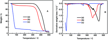 | ||
Fig. 1 (A) TGA and (B) DTA studies of 0.1 mol L−1 LiODFB-PP13*TFSI (a), 0.4 mol L−1 LiODFB-PP13*TFSI/DMC (8![[thin space (1/6-em)]](https://www.rsc.org/images/entities/char_2009.gif) : :![[thin space (1/6-em)]](https://www.rsc.org/images/entities/char_2009.gif) 2 v/v) (b), 0.4 mol L−1 LiODFB-DMC (c). 2 v/v) (b), 0.4 mol L−1 LiODFB-DMC (c). | ||
Fig. 1B shows the differential thermal analysis (DTA) of these electrolytes. For the electrolyte 0.4 mol L−1 LiODFB-DMC, the endothermic peaks can be attributed to the evaporation of DMC at 50 °C and decomposition of LiODFB at 250 °C. However, the decomposition temperatures of LiODFB and PP13*TFSI are delayed to 370 and 445 °C, respectively, for the electrolyte 0.1 mol L−1 LiODFB-PP13*TFSI, which are attributed to the strong interaction between cations and anions. The decomposition temperature of LiODFB and PP13*TFSI are decreased slightly when the DMC is used as co-solvent additive, which is ascribed to the weakened interactions among ions in the presence of molecule solvent. However, it can be noted that the peak intensity of PP13*TFSI thermal decomposition is lower for 0.4 mol L−1 LiODFB-PP13*TFSI/DMC electrolyte than the case for 0.1 mol L−1 LiODFB-PP13*TFSI electrolyte, indicating that the weight loss is decreased in per unit temperature. Meanwhile, the peak intensity of LiODFB thermal decomposition becomes strong resulting from higher Li salt concentration. These results confirm the thermal stability is improved for the mixture electrolyte 0.4 mol L−1 LiODFB-PP13*TFSI/DMC.
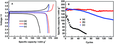
In order to study the electrochemical stability of these electrolytes, the charge–discharge cycles of LiFePO4/Li half-cells were conducted at the 0.05C rate for the first four cycles and 0.1C rate for the subsequent cycles in three electrolytes in the potential range of 2.2–4.1 V, as shown in Fig. 2. Apparently, the 0.1 mol L−1 LiODFB-PP13*TFSI electrolyte shows a great potential separation about 0.14 V between the charge and discharge voltage plateau, as shown in Fig. 2A, and the cells with 0.1 mol L−1 LiODFB-PP13*TFSI electrolyte acquire a first discharge capacity of 132 mAh g−1 and a coulombic efficiency of 78.81%. In the cases of 0.4 mol L−1 LiODFB-PP13*TFSI/DMC (8![[thin space (1/6-em)]](https://www.rsc.org/images/entities/char_2009.gif) :
:![[thin space (1/6-em)]](https://www.rsc.org/images/entities/char_2009.gif) 2 v/v) and 0.4 mol L−1 LiODFB-DMC, the polarization loss between the charge–discharge voltage plateau become smaller to 0.07 V. Obviously, the use of DMC can decrease the cell polarization.37,38 This may be attributed to the effective SEI formation leading to the improved Li ion transport in the electrode and electrode/electrolyte interface. In addition, their first discharge capacities are comparable to the theory capacity (170 mAh g−1). The first discharge capacity and coulombic efficiency arise to 170.5 mAh g−1 and 90.4% for 0.4 mol L−1 LiODFB-PP13*TFSI/DMC (8
2 v/v) and 0.4 mol L−1 LiODFB-DMC, the polarization loss between the charge–discharge voltage plateau become smaller to 0.07 V. Obviously, the use of DMC can decrease the cell polarization.37,38 This may be attributed to the effective SEI formation leading to the improved Li ion transport in the electrode and electrode/electrolyte interface. In addition, their first discharge capacities are comparable to the theory capacity (170 mAh g−1). The first discharge capacity and coulombic efficiency arise to 170.5 mAh g−1 and 90.4% for 0.4 mol L−1 LiODFB-PP13*TFSI/DMC (8![[thin space (1/6-em)]](https://www.rsc.org/images/entities/char_2009.gif) :
:![[thin space (1/6-em)]](https://www.rsc.org/images/entities/char_2009.gif) 2 v/v) electrolyte as well as 165.2 mAh g−1 and 97.05% for 0.4 mol L−1 LiODFB-DMC electrolyte. However, the cell with the 0.4 mol L−1 LiODFB-PP13*TFSI/DMC (8
2 v/v) electrolyte as well as 165.2 mAh g−1 and 97.05% for 0.4 mol L−1 LiODFB-DMC electrolyte. However, the cell with the 0.4 mol L−1 LiODFB-PP13*TFSI/DMC (8![[thin space (1/6-em)]](https://www.rsc.org/images/entities/char_2009.gif) :
:![[thin space (1/6-em)]](https://www.rsc.org/images/entities/char_2009.gif) 2 v/v) electrolyte shows the best stable cycling performance for 150 cycles. After 100 cycles, a discharge capacity of 160 mAh g−1 is obtained, thus the capacity retention reach up to ca. 94.1%, as shown in Fig. 2B. The excellent electrochemical cycles can be ascribed to the perfect SEI film on the LiFePO4 electrodes.
2 v/v) electrolyte shows the best stable cycling performance for 150 cycles. After 100 cycles, a discharge capacity of 160 mAh g−1 is obtained, thus the capacity retention reach up to ca. 94.1%, as shown in Fig. 2B. The excellent electrochemical cycles can be ascribed to the perfect SEI film on the LiFePO4 electrodes.
Rate performance is also one of the most important characteristics of Li ion transport. Thus, the rate capability of LiFePO4 electrodes in different electrolytes were investigated from 0.05C to 2C, as shown in Fig. 3. The discharge capacity of the cells with the electrolytes 0.4 mol L−1 LiODFB-PP13*TFSI/DMC and 0.4 mol L−1 LiODFB-DMC could reach up to 168 mAh g−1 at lower current densities of 0.05C and 0.1C, which is close to the theoretical capacity of 170 mAh g−1. The discharge capacity of the cells with the electrolytes 0.1 mol L−1 LiODFB-PP13*TFSI is only ca. 130 mAh g−1 during the initial five cycles, and the discharge capacity is significantly decreased with the increase of current densities. However, a discharge capacity of the cells with the electrolytes 0.4 mol L−1 LiODFB-PP13*TFSI/DMC is similar to that case with 0.4 mol L−1 LiODFB-DMC being capable to keep stable to 1C, while the discharge capacity is ca. 147 mAh g−1 and 128 mAh g−1 at 2C, respectively, which are much higher than the case with the electrolyte 0.1 mol L−1 LiODFB-PP13*TFSI. Compared to the electrolyte 0.4 mol L−1 LiODFB-DMC, the small loss capacity at 2C for the electrolyte 0.4 mol L−1 LiODFB-PP13*TFSI/DMC is resulted from the higher viscosity in the presence of IL PP13*TFSI. However, the discharge capacities are not affected by the viscosity at low rate. In summary, it is suggested that the Li ion transport is improved a lot because of the addition of DMC to the IL.
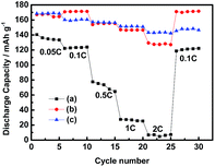 | ||
Fig. 3 Rate performance of Li/LiFePO4 half-cells containing 0.1 mol L−1 LiODFB-PP13*TFSI (a), 0.4 mol L−1 LiODFB-PP13*TFSI/DMC (8![[thin space (1/6-em)]](https://www.rsc.org/images/entities/char_2009.gif) : :![[thin space (1/6-em)]](https://www.rsc.org/images/entities/char_2009.gif) 2 v/v) (b), 0.4 mol L−1 LiODFB-DMC (c) electrolytes. 2 v/v) (b), 0.4 mol L−1 LiODFB-DMC (c) electrolytes. | ||
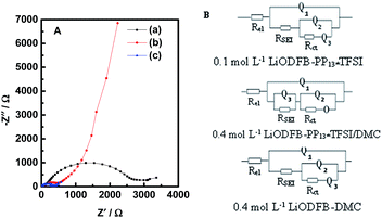
Electrochemical impedance measurements (EIS) of Li/LiFePO4 cells with the three electrolytes were carried out after 20 cycles. The obtained Nyquist plots, as shown in Fig. 4A, were fitted with equivalent circuits in Fig. 4B. The use of a Constant Phase Element (CPE) Q instead of a capacitor was due to the existence of depressed semicircles in the system.39.A CPE represents a resistor when n = 0, a capacitor with capacitance of C when n = 1, an inductor when n = −1, and a Warburg resistance when n = 0.5. The simulation results are listed in Table 1. The relative standard error for most parameters obtained from fitting the experimental impedance spectra are within 10%, demonstrating that the proposed model describes the experimental data satisfactorily. All impedance spectra are composed of a semicircle in the high and middle frequency ranges and an oblique line in the low frequency range. The intersection of the EIS diagram with the real axis refers to the bulk resistance (Rel), which may be attributable to electrolyte resistance. The resistance values RSEI corresponding to the semicircle represents the formation of SEI and the contact resistance of the electrode and the electrolyte and Rct can be assigned to the charge transfer resistance. The oblique line stands for the behavior of the electrode including the Li ion insertion and the corresponding charge transfer.40–42 As can be seen from Table 1, the highest bulk resistance Rel (ca. 39.14 Ω) is obtained in the electrolyte 0.1 mol L−1 LiODFB-PP13*TFSI. However, the bulk resistance Rel (ca. 6.013 Ω) in the electrolyte 0.4 mol L−1 LiODFB-PP13*TFSI/DMC is significantly decreased because of the addition of DMC, which is, one hand, ascribed to the decreased viscosity because of the addition of DMC, on the other hand, the good wettability between the electrolyte and the membrane with the presence of the anion TFSI− in the ionic liquid PP13*TFSI.43,44 A significantly decreased of the values RSEI (ca. 121.1 Ω) and Rct (ca. 387.2 Ω) reflect the perfect formation of SEI film on the LiFePO4 electrode. The different resistance values of RSEI and Rct are mainly caused by the different components of SEI film, as shown in the following XPS results. O represents the finite length diffusion, i.e. the concentration of Li ion is fixed at a surface.
| Electrolytes | 0.1 mol L−1 LiODFB-PP13*TFSI | 0.4 mol L−1 LiODFB-PP13*TFSI/DMC (8![[thin space (1/6-em)]](https://www.rsc.org/images/entities/char_2009.gif) : :![[thin space (1/6-em)]](https://www.rsc.org/images/entities/char_2009.gif) 2 v/v) 2 v/v) |
0.4 mol L−1 LiODFB-DMC | |||
|---|---|---|---|---|---|---|
| Parameters | Values | Error (%) | Values | Error (%) | Values | Error (%) |
| Rel (Ω) | 39.14 | 0.741 | 6.013 | 1.235 | 3.237 | 2.206 |
| Q1–Y0 | 4.772 × 10⁻⁶ | 10.4 | 2.304 × 10⁻⁶ | 5.508 | 4.082 × 10⁻⁶ | 14.2 |
| Q1–n | 0.782 | 1.230 | 0.8608 | 0.582 | 0.8561 | 1.369 |
| RSEI (Ω) | 221.2 | 4.297 | 121.1 | 2.47 | 63.29 | 9.298 |
| Q2–Y0 | 6.562 × 10⁻⁶ | 7.746 | 1.476 × 10⁻⁶ | 1.849 | 2.59 × 10⁻⁵ | 9.278 |
| Q2–n | 0.873 | 1.182 | 0.8444 | 0.965 | 0.711 | 1.923 |
| Rct (Ω) | 2305 | 2.595 | 387.2 | 1.998 | 274.2 | 2.703 |
| Q3–Y0 | 2.396 × 10⁻⁴ | 14.08 | 2.506 × 10⁻⁴ | 7.461 | 1.137 × 10⁻² | 4.296 |
| Q3–n | 0.3026 | 12.73 | 0.7678 | 1.547 | 1.826 | 5.25 |
| O–Y0 | — | — | 2.135 × 10⁻³ | 3.849 | — | — |
| O–B | — | — | 0.8843 | 3.337 | — | — |
Fig. 5A shows the SEM images of the pristine and cycled LiFePO4 electrodes extracted from cells after 20 cycles at room temperature. The morphology of the pristine LiFePO4 electrode has a spherical shape. Yet changes to the LiFePO4 electrodes can be observed after being cycled. For the cycled LiFePO4 electrodes, the electrodes surface are rough and obscure, indicating that a surface film is generated on the LiFePO4 electrode, which leads to different interphase resistance between the electrolyte and electrode, as discussed EIS above.
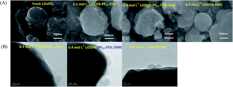 | ||
| Fig. 5 (A) SEM images of fresh and cycled LiFePO4 electrodes; (B) TEM images of the cycled LiFePO4 electrodes in different electrolytes. | ||
To further study the microstructural changes on the surface of the LiFePO4 electrodes with different electrolytes, TEM images were acquired in Fig. 5B. A thin and intact surface film surrounds the LiFePO4 particles in the 0.4 mol L−1 LiODFB-PP13*TFSI/DMC electrolyte, and the thickness of the surface layer is about ranged 20 nm; while much imperfect surface films was formed on the LiFePO4 particles in the other two electrolytes. TEM examination further confirms that a thin and stable surface film formed on the LiFePO4 electrode with the electrolyte 0.4 mol L−1 LiODFB-PP13*TFSI/DMC during cycling.
For the purpose of further clarification for the changes to the surface of the LiFePO4 electrodes after 20 cycles in different electrolytes. Complementary information of chemicals distribution of the surface film on the cycled LiFePO4 electrodes is studied by XPS patterns, as shown in Fig. 6.
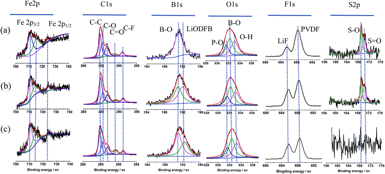 | ||
Fig. 6 XPS patterns of cycled LiFePO4 electrodes in the different electrolytes: (a) 0.1 mol L−1 LiODFB-PP13*TFSI, (b) 0.4 mol L−1 LiODFB-PP13*TFSI/DMC (8![[thin space (1/6-em)]](https://www.rsc.org/images/entities/char_2009.gif) : :![[thin space (1/6-em)]](https://www.rsc.org/images/entities/char_2009.gif) 2 v/v), (c) 0.4 mol L−1 LiODFB-DMC. 2 v/v), (c) 0.4 mol L−1 LiODFB-DMC. | ||
According to the reports, pristine LiFePO4 shows a Fe 2p3/2 main peak at 710 eV with a satellite peak at 715 eV (724 and 729 eV for Fe 2p1/2, respectively).45 A satellite peak (715 eV) provided good evidence for the oxidation states of Fe2+ ions in the LiFePO4 samples.46 While, the peak at 711–712 eV is characteristic of Fe3+ from lithium-deintercalated phase FePO4.45 Thus Fe2p spectra could confirm the structure purity of the cycled LiFePO4 electrodes.47 As shown in Fig. 6, the main peaks of discharged LiFePO4 electrodes are in good agreement with the pristine material, and the peak characteristic of Fe3+ is not appear, indicating the good reversibility of the Fe3+/Fe2+ redox process upon charge/discharge cycles. The C1s peaks C![[double bond, length as m-dash]](https://www.rsc.org/images/entities/char_e001.gif) O at 289.2 eV, C–O at 286.7 eV and the B1s peak B–O at 191.01 eV and the O1s peak B–O at 532.2 eV confirm the formation of dimmers (CO2BF2)2 in SEI film, which is from the oxidative reaction of LiODFB. It is assumed that the presence of oligomeric species in the SEI makes the surface film elastic.48 The B1s peak at 192.42 eV is attributed to LiODFB, which is not observed on the LiFePO4 electrode cycled in the electrolyte 0.1 mol L−1 LiODFB-PP13*TFSI, attributed to the low concentration of LiODFB in PP13*TFSI. The F1s peak at 685.8 eV shows the presence of LiF,49 which may be from the oxidative reaction of ODFB− and TFSI− anions in electrolyte. In addition, the F1s peak at 688.5 eV along with C–F peak at 291.1 eV of C1s spectra represents the PVDF.45 The O1s spectra were observed with peaks from PO43− at 531.6 eV and O–H at 533.04 eV.50
O at 289.2 eV, C–O at 286.7 eV and the B1s peak B–O at 191.01 eV and the O1s peak B–O at 532.2 eV confirm the formation of dimmers (CO2BF2)2 in SEI film, which is from the oxidative reaction of LiODFB. It is assumed that the presence of oligomeric species in the SEI makes the surface film elastic.48 The B1s peak at 192.42 eV is attributed to LiODFB, which is not observed on the LiFePO4 electrode cycled in the electrolyte 0.1 mol L−1 LiODFB-PP13*TFSI, attributed to the low concentration of LiODFB in PP13*TFSI. The F1s peak at 685.8 eV shows the presence of LiF,49 which may be from the oxidative reaction of ODFB− and TFSI− anions in electrolyte. In addition, the F1s peak at 688.5 eV along with C–F peak at 291.1 eV of C1s spectra represents the PVDF.45 The O1s spectra were observed with peaks from PO43− at 531.6 eV and O–H at 533.04 eV.50
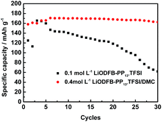 | ||
Fig. 7 Long charge–discharge studies of LiFePO4 electrodes in 0.1 mol L−1 LiODFB-PP13*TFSI electrolyte and 0.4 mol L−1 LiODFB-PP13*TFSI/DMC (8![[thin space (1/6-em)]](https://www.rsc.org/images/entities/char_2009.gif) : :![[thin space (1/6-em)]](https://www.rsc.org/images/entities/char_2009.gif) 2 v/v) electrolyte at 60 °C. 2 v/v) electrolyte at 60 °C. | ||
In addition, the main peak of S2p spectra at 169.4 eV is corresponded to sulfur oxidation state +4,51 which is not observed in the electrolyte 0.4 mol L−1 LiODFB/DMC, indicating that the anion TFSI− decomposed to join in the SEI formation on the LiFePO4 electrodes cycled in the electrolyte 0.1 mol L−1 LiODFB-PP13*TFSI and 0.4 mol L−1 LiODFB-PP13*TFSI/DMC. Sulfur oxidation state +4 consolidates the SEI layer by adherent compounds Li2SO4.52 Taking the cycling performance into consideration, the cell with the electrolyte 0.4 mol L−1 LiODFB-PP13*TFSI/DMC has the excellent cycle stability, revealing that the joint of anions TFSI− and ODFB− enhance the SEI forming ability of the electrolyte, and the concentration of ODFB− play an important role in the improvement of the SEI performance.
Finally, high-temperature electrochemical behaviors of the LiFePO4 electrode were studied. The long cycling performance of LiFePO4/Li cells with two different electrolytes were performed at 60 °C. The results are depicted in Fig. 7. It is found that LiFePO4/Li cell with 0.4 mol L−1 LiODFB-PP13*TFSI/DMC (8![[thin space (1/6-em)]](https://www.rsc.org/images/entities/char_2009.gif) :
:![[thin space (1/6-em)]](https://www.rsc.org/images/entities/char_2009.gif) 2 v/v) electrolyte shows superior cycling performance, delivering first discharge capacity of 158 mAh g−1 and first coulombic efficiency of 90.22% and retaining 162.5 mAh g−1 at 30th cycles. However, when 0.1 mol L−1 LiODFB-PP13*TFSI electrolyte was used, capacity fading is significantly accelerated as the cycle numbers was increased. The discharge capacity of 62 mAh g−1 was retained at 30th cycles.
2 v/v) electrolyte shows superior cycling performance, delivering first discharge capacity of 158 mAh g−1 and first coulombic efficiency of 90.22% and retaining 162.5 mAh g−1 at 30th cycles. However, when 0.1 mol L−1 LiODFB-PP13*TFSI electrolyte was used, capacity fading is significantly accelerated as the cycle numbers was increased. The discharge capacity of 62 mAh g−1 was retained at 30th cycles.
To get a deeper insight into the reason of perfect cycle performance, cycled LiFePO4/Li half-cells were disassembled, and the LiFePO4 electrodes were carefully harvested and then analyzed by TEM. TEM micrographs of cycled LiFePO4 electrodes in 0.1 mol L−1 LiODFB-PP13* TFSI and 0.4 mol L−1 LiODFB-PP13*TFSI/DMC electrolytes are shown in Fig. 8. The cycled LiFePO4 electrode in 0.1 mol L−1 LiODFB-PP13* TFSI electrolyte is coated with quite thick film layer, which reveals continuous electrolyte oxidation and parasitic electrode/electrolyte reactions and thus leads to fast capacity fading during cycling. However, the cycled LiFePO4 electrode in 0.4 mol L−1 LiODFB-PP13*TFSI/DMC electrolyte is covered with a thin and uniform film layer, which suppresses continuous electrolyte/electrode reactions and thus leads to the excellent electrochemical stability. The difference between the two surface SEI films results from the changes to the surface film species, as shown in Fig. S2.† The peak of B–O (at 191 eV in the B1s spectrum or at 532.2 eV in the O1s spectrum) is observed on the LiFePO4 electrode extracted from the cell with 0.4 mol L−1 LiODFB-PP13*TFSI/DMC electrolyte suggested the generation of dimmers (CO2BF2)2 in SEI film. Meanwhile, in the Fe2p spectrum, as discussed in Fig. 6, the main peaks of discharged LiFePO4 electrodes are in good agreement with the pristine material, and the peak characteristic of Fe3+ is not appear, indicating the good reversibility of the Fe3+/Fe2+ redox process upon charge/discharge cycles in electrolyte 0.4 mol L−1 LiODFB-PP13*TFSI/DMC. These cases are not appear in the spectra of LiFePO4 electrode extracted from cell with 0.1 mol L−1 LiODFB-PP13*TFSI electrolyte. Hence it can be suggested that the addition of DMC increases the solubility of LiODFB in the IL and makes the ability of film-formation of LiODFB salt exhibited obviously at high temperature.
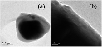 | ||
| Fig. 8 TEM analysis of LiFePO4 electrodes cycled in (a) 0.1 mol L−1 LiODFB-PP13*TFSI and (b) 0.4 mol L−1 LiODFB-PP13*TFSI/DMC electrolytes after 30 cycles at 60 °C. | ||
The cells cycled at 60 °C after 30 cycles were dismantled in a glove box and the separators were taken out to be studies by EDX, as shown in Fig. 9. The separators exhibited a apparent difference that can be seen by the naked eyes. The separator in the cell with 0.1 mol L−1 LiODFB-PP13*TFSI electrolyte was deep brownish, however, the separator in the cell with 0.4 mol L−1 LiODFB-PP13*TFSI/DMC electrolyte was clear white, as shown in the inset of Fig. 9. In order to confirm this, EDX analysis of the separators was carried out. It is apparent that the dissolution of Fe element is suppressed largely in the electrolyte 0.4 mol L−1 LiODFB-PP13*TFSI/DMC, indicating that an effective SEI film was formed on the LiFePO4 electrode to protect the electrode structure. At the same time, the decrease of F and S elements on the separator surface reveals the small discomposition of TFSI− anions, and the formation of the SEI film in the electrolyte 0.4 mol L−1 LiODFB-PP13*TFSI/DMC is dominated by the oxidation of ODFB− anions. It is the reason why the capacity retention is higher in the electrolyte 0.4 mol L−1 LiODFB-PP13*TFSI/DMC than that in the electrolyte 0.1 mol L−1 LiODFB-PP13*TFSI.
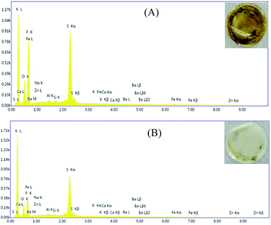 | ||
Fig. 9 EDX analysis of the separator cycled in (A) 0.1 mol L−1 LiODFB-PP13*TFSI and (B) 0.4 mol L−1 LiODFB-PP13*TFSI/DMC (8![[thin space (1/6-em)]](https://www.rsc.org/images/entities/char_2009.gif) : :![[thin space (1/6-em)]](https://www.rsc.org/images/entities/char_2009.gif) 2 v/v) electrolytes at 60 °C. 2 v/v) electrolytes at 60 °C. | ||
4. Conclusions
The electrolyte of 0.4 mol L−1 LiODFB-PP13*TFSI/DMC (8![[thin space (1/6-em)]](https://www.rsc.org/images/entities/char_2009.gif) :
:![[thin space (1/6-em)]](https://www.rsc.org/images/entities/char_2009.gif) 2 v/v) was prepared, and DMC is used to enhance the solubility of LiODFB in IL PP13*TFSI. For comparison, the electrolytes 0.1 mol L−1 LiODFB-PP13*TFSI and 0.4 mol L−1 LiODFB-DMC also were prepared. The LiFePO4/Li cells were operated with the above three electrolytes at room temperature. In addition, considering the poor thermal stability of electrolyte 0.4 mol L−1 LiODFB-DMC, LiFePO4/Li cells with electrolytes 0.1 mol L−1 LiODFB-PP13*TFSI and 0.4 mol L−1 LiODFB-PP13*TFSI/DMC (8
2 v/v) was prepared, and DMC is used to enhance the solubility of LiODFB in IL PP13*TFSI. For comparison, the electrolytes 0.1 mol L−1 LiODFB-PP13*TFSI and 0.4 mol L−1 LiODFB-DMC also were prepared. The LiFePO4/Li cells were operated with the above three electrolytes at room temperature. In addition, considering the poor thermal stability of electrolyte 0.4 mol L−1 LiODFB-DMC, LiFePO4/Li cells with electrolytes 0.1 mol L−1 LiODFB-PP13*TFSI and 0.4 mol L−1 LiODFB-PP13*TFSI/DMC (8![[thin space (1/6-em)]](https://www.rsc.org/images/entities/char_2009.gif) :
:![[thin space (1/6-em)]](https://www.rsc.org/images/entities/char_2009.gif) 2 v/v) were operated at 60 °C.
2 v/v) were operated at 60 °C.
IL PP13*TFSI exhibits low viscosity and high conductivity at room temperature attributing to the C–C double bond in PP13*+ cations side chains. Therefore the electrolyte 0.4 mol L−1 LiODFB-PP13*TFSI/DMC (8![[thin space (1/6-em)]](https://www.rsc.org/images/entities/char_2009.gif) :
:![[thin space (1/6-em)]](https://www.rsc.org/images/entities/char_2009.gif) 2 v/v) possesses low viscosity and satisfying thermal stability. LiFePO4 cathode also exhibits perfect cycling and rate performances in the electrolyte 0.4 mol L−1 LiODFB-PP13*TFSI/DMC (8
2 v/v) possesses low viscosity and satisfying thermal stability. LiFePO4 cathode also exhibits perfect cycling and rate performances in the electrolyte 0.4 mol L−1 LiODFB-PP13*TFSI/DMC (8![[thin space (1/6-em)]](https://www.rsc.org/images/entities/char_2009.gif) :
:![[thin space (1/6-em)]](https://www.rsc.org/images/entities/char_2009.gif) 2 v/v). These perfect electrochemical performances can be mainly attributed to two reasons: on the one hand, the addition of DMC increases the solubility of LiODFB in the IL PP13*TFSI, facilitating the formation of elastic dimmers (CO2BF2)2 from ODFB− anions decomposition on the LiFePO4 surface; on the other hand, sulfur oxidation state +4 from TFSI− anions decomposition consolidates the SEI layer by adherent compounds Li2SO4. Due to the outstanding SEI film forming ability of combination of ODFB− and TFSI− anions, prior to the only ODFB− or TFSI− anions decomposition, LiFePO4/Li cell in electrolyte 0.4 mol L−1 LiODFB-PP13*TFSI/DMC (8
2 v/v). These perfect electrochemical performances can be mainly attributed to two reasons: on the one hand, the addition of DMC increases the solubility of LiODFB in the IL PP13*TFSI, facilitating the formation of elastic dimmers (CO2BF2)2 from ODFB− anions decomposition on the LiFePO4 surface; on the other hand, sulfur oxidation state +4 from TFSI− anions decomposition consolidates the SEI layer by adherent compounds Li2SO4. Due to the outstanding SEI film forming ability of combination of ODFB− and TFSI− anions, prior to the only ODFB− or TFSI− anions decomposition, LiFePO4/Li cell in electrolyte 0.4 mol L−1 LiODFB-PP13*TFSI/DMC (8![[thin space (1/6-em)]](https://www.rsc.org/images/entities/char_2009.gif) :
:![[thin space (1/6-em)]](https://www.rsc.org/images/entities/char_2009.gif) 2 v/v) presents a best electrochemical performances. It is worth noting that the decomposition of ODFB− anion is dominant and TFSI− anion is auxiliary during the formation of SEI film on LiFePO4 electrode.
2 v/v) presents a best electrochemical performances. It is worth noting that the decomposition of ODFB− anion is dominant and TFSI− anion is auxiliary during the formation of SEI film on LiFePO4 electrode.
In summary, IL cations containing C![[double bond, length as m-dash]](https://www.rsc.org/images/entities/char_e001.gif) C in cations side chains can be regarded as a promising electrolyte solvent candidate because of its low viscosity and high conductivity. Li salt LiODFB should be combined with linear solvent to increase its solubility in IL to improve the electrochemical performance of the electrolyte.
C in cations side chains can be regarded as a promising electrolyte solvent candidate because of its low viscosity and high conductivity. Li salt LiODFB should be combined with linear solvent to increase its solubility in IL to improve the electrochemical performance of the electrolyte.
Conflicts of interest
There are no conflicts to declare.Acknowledgements
This work was supported by the National High-tech R&D Program, China (2015AA034601). The authors are also grateful for funding from the National Natural Science Foundation of China (NSFC, contract No. 21473120, 51272168, 21543010 and 21301124).References
- B. Scrosatiand and J. Garche, J. Power Sources, 2010, 195, 2419–2430 CrossRef.
- J. Y. Yong, V. K. Ramachandaramurthy, K. M. Tan and N. Mithulananthan, Renewable Sustainable Energy Rev., 2015, 49, 365–385 CrossRef.
- F. Orecchini, A. Santiangeli and A. Dell-Era, Lithium Ion Batteries, 2014, 205–248 Search PubMed.
- M. S. Whittingham, Chem. Rev., 2014, 114, 11414–11443 CrossRef CAS PubMed.
- Y. J. Mai, H. Luo, X. Y. Zhao, J. L. Wang, J. Davis, L. J. Lyons and L. Z. Zhang, Ionics, 2014, 20, 1207–1215 CrossRef CAS.
- N. Madria, T. A. Arunkumar, N. G. Nair, A. Vadapalli, Y. W. Huang, S. C. Jones and V. P. Reddy, J. Power Sources, 2013, 234, 277–284 CrossRef CAS.
- L. Lombardo, S. Brutti, M. A. Navarra, S. Panero and P. Reale, J. Power Sources, 2013, 227, 8–14 CrossRef CAS.
- Q. Du, X. Fu, S. Liu and L. Niu, Polym. Int., 2012, 61, 222–227 CrossRef CAS.
- S. Ferrari, E. Quartarone, C. Tomasi, D. Ravelli, S. Protti, M. Fagnoni and P. Mustarelli, J. Power Sources, 2013, 235, 142–147 CrossRef CAS.
- A. Chagnes, M. Diaw, B. Carré, P. Willmann and D. Lemordant, J. Power Sources, 2005, 157, 82–88 CrossRef.
- H. S. Jeong, J. H. Kim and S. Y. Lee, J. Mater. Chem., 2010, 20, 9180–9186 RSC.
- M. Hirayama, H. Ido, K. Kim, W. Cho, K. Tamura, J. Mizuki and R. Kanno, J. Am. Chem. Soc., 2010, 132, 15268–15276 CrossRef CAS PubMed.
- L. Lombardo, S. Brutti, M. A. Navarra, S. Panero and P. Reale, J. Power Sources, 2013, 227, 8–14 CrossRef CAS.
- I. Quinzeni, S. Ferrari, E. Quartarone, C. Tomasi, M. Fagnoni and P. Mustarelli, J. Power Sources, 2013, 237, 204–209 CrossRef CAS.
- R. S. Kühnel, N. Böckenfeld, S. Passerini, M. Winter and A. Bald-ucci, Electrochim. Acta, 2011, 56, 4092–4099 CrossRef.
- K. Kim, Y. H. Cho and H. C. Shin, J. Power Sources, 2013, 225, 113–118 CrossRef CAS.
- M. Wang, Z. Shan, J. Tian, X. Liu, H. Liu and K. Zhu, Electrochim. Acta, 2013, 95, 301–307 CrossRef CAS.
- A. Guerfi, M. Dontigny, P. Charest, M. Petitclerc, M. Lagacé, A. Vijh and K. Zaghib, J. Power Sources, 2010, 195, 845–852 CrossRef CAS.
- B. B. Yang, C. H. Li, J. H. Zhou, J. H. Liu and Q. L. Zhang, Electrochim. Acta, 2014, 148, 39–45 CrossRef CAS.
- S. Theivaprakasam, D. R. MacFarlane and S. Mitra, Electrochim. Acta, 2015, 180, 737–745 CrossRef CAS.
- C. Arbizzani, G. Gabrielli and M. Mastragostino, J. Power Sources, 2011, 196, 4801–4805 CrossRef CAS.
- H. Li, J. Pang, Y. Yin, W. Zhuang, H. Wang, C. Zhai and S. Lu, RSC Adv., 2013, 3, 13907–13914 RSC.
- L. Lombardo, S. Brutti, M. A. Navarra, S. Panero and P. Reale, J. Power Sources, 2013, 227, 8–14 CrossRef CAS.
- R.-S. Kühnel, N. Böckenfeld, S. Passerini, M. Winter and A. Balducci, Electrochim. Acta, 2011, 56, 4092–4099 CrossRef.
- D. T. Shieh, P. H. Hsieh and M. H. Yang, J. Power Sources, 2007, 174, 663–667 CrossRef CAS.
- S. S. Zhang, Electrochem. Commun., 2006, 8, 1423–1428 CrossRef CAS.
- S. S. Zhang, J. Power Sources, 2007, 163, 713–718 CrossRef CAS.
- Z. H. Chen, J. Liu and K. Amine, J. Electrochem. Soc., 2007, 3, A45–A47 Search PubMed.
- R. J. Chen, Y. Chen, L. Zhu, Q. Z. Zhu and F. Wu, J. Mater. Chem. A, 2015, 3, 6366–6372 CAS.
- F. Wu, Q. Zhu, R. Chen, N. Chen, Y. Chen and L. Li, Chem. Sci., 2015, 6, 7274–7283 RSC.
- J. Reiter and M. Nadherna, Electrochim. Acta, 2012, 71, 22–26 CrossRef CAS.
- J. Huang and A. F. Hollenkamp, J. Phys. Chem. C, 2010, 114, 21840–21847 CAS.
- A. S. Best, A. I. Bhatt and A. F. Hollenkamp, J. Electrochem. Soc., 2010, 157, A903–A911 CrossRef CAS.
- E. Paillard, Q. Zhou, W. A. Henderson, G. B. Appetecchi, M. Montanino and S. Passerini, J. Electrochem. Soc., 2009, 156, A891–A895 CrossRef CAS.
- R. Younesi, G. M. Veith, P. Johansson, K. Edströmbe and T. Vegge, Energy Environ. Sci., 2015, 8, 1905–1922 CAS.
- H. Li, J. Pang, Y. Yin, W. Zhuang, H. Wang, C. Zhai and S. Lu, RSC Adv., 2013, 3, 13907–13914 RSC.
- S. Theivaprakasam, D. R. MacFarlane and S. Mitra, Electrochim. Acta, 2015, 180, 737–745 CrossRef CAS.
- G. A. Elia, U. Ulissi, S. Jeong, S. Passerini and J. Hassoun, Energy Environ. Sci., 2016, 9, 3210–3220 CAS.
- B. Evgenij, Impedance Spectroscopy: Theory, Experiment, and Applications, ed. J. R. Macdonald, Wiley, New Jersey, 2005 Search PubMed.
- P. Lu, C. Li, E. W. Schneider and S. J. Harris, J. Phys. Chem. C, 2014, 118, 896–903 CAS.
- S. H. Lee, H. G. You, K. S. Han, J. Kim, I. H. Jung and J. H. Song, J. Power Sources, 2014, 247, 307–313 CrossRef CAS.
- Z. Cai, Y. Liu, J. H. Zhao, L. Li, Y. M. Zhang and J. Zhang, J. Power Sources, 2012, 202, 341–346 CrossRef CAS.
- R. J. Chen, Y. Chen, L. Zhu, Q. Z. Zhu, F. Wu and L. Li, J. Mater. Chem. A, 2015, 3, 6366–6372 CAS.
- M. M. Huie, R. A. DiLeo, A. C. Marschilok, K. J. Takeuchi and E. S. Takeuchi, ACS Appl. Mater. Interfaces, 2015, 7, 11724–11731 CAS.
- R. Dedryvère, M. Maccario, L. Croguennec, F. Le Cras, C. Delmas and D. Gonbeau, Chem. Mater., 2008, 20, 7164–7170 CrossRef.
- M. S. Bhuvaneswari, N. N. Bramnik, D. Ensling, H. Ehrenberg and W. Jaegermann, J. Power Sources, 2008, 180, 553–560 CrossRef CAS.
- L. Hu, T. W. Zhang, J. W. Liang, Y. C. Zhu, K. L. Zhang and Y. T. Qian, RSC Adv., 2016, 6, 456–463 RSC.
- T. Schedlbauer, S. Krüger, R. Schmitz, R. W. Schmitz, C. Schreiner, H. J. Gores, S. Passerini and M. Winter, Electrochim. Acta, 2013, 92, 102–107 CrossRef CAS.
- H. Duncan, Y. A. Lebdeh and I. J. Davidson, J. Electrochem. Soc., 2010, 157, A528–A535 CrossRef CAS.
- A. Tron, Y. N. Jo, S. H. Oh, Y. Park and J. Mun, ACS Appl. Mater. Interfaces, 2017, 9, 12391–12399 CAS.
- K. C. Högström, M. Hahlin, S. Malmgren, M. Gorgoi, H. Rensmo and K. Edström, J. Phys. Chem. C, 2014, 118, 12649–12660 Search PubMed.
- G. A. Elia, U. Ulissi, S. Jeong, S. Passerini and J. Hassoun, Energy Environ. Sci., 2016, 9, 3210–3220 CAS.
Footnote |
| † Electronic supplementary information (ESI) available. See DOI: 10.1039/c7ra10045k |
| This journal is © The Royal Society of Chemistry 2017 |

