 Open Access Article
Preparation of cis-pinane via α-pinene hydrogenation in water by using Ru nanoparticles immobilized in functionalized amphiphilic mesoporous silica†
Lihua Xiea,
Xiaoyan Wanga,
Fengli Yua,
Bing Yuan a,
Congxia Xie
 *a and
Shitao Yu
 b
b
aState Key Laboratory Base of Eco-chemical Engineering, College of Chemistry and Molecular Engineering, Qingdao University of Science and Technology, Qingdao 266042, Shandong, China. E-mail: xiecongxia@126.com; Fax: +86-532-84022719; Tel: +86-532-84022719
bCollege of Chemical Engineering, Qingdao University of Science and Technology, Qingdao 266042, Shandong, China
First published on 6th November 2017
Abstract
Amphiphilic mesoporous silica modified with trimethoxy (3,3,3-trifluoropropyl) silane (TFPS) and (3-aminopropyl) trimethoxysilane (APTS) was prepared by one-step synthesis. The structure and morphology of the mesoporous silica were characterized and confirmed by solid-state nuclear magnetic resonance, X-ray diffraction (XRD), N2 adsorption–desorption, Fourier transfer infrared spectroscopy (FT-IR), scanning electron microscopy (SEM) and transmission electron microscopy (TEM). Meanwhile, the thermostability of the amphiphilic mesoporous silica was detected by thermogravimetric (TG) technique. Highly dispersed Ru nanoparticles supported on such amphiphilic mesoporous silica (marked as Ru/MF@MN) were synthesized by wet impregnation method with the assistance of ultrasonic. The catalyst was characterized by X-ray photoelectron spectroscopy (XPS) and inductively coupled plasma-atomic emission spectrometry (ICP-AES). In water medium, Ru/MF@MN was used in α-pinene hydrogenation to prepare cis-pinane. Under the optimum reaction conditions (35 °C, 2 MPa H2, 1 h, m (H2O)![[thin space (1/6-em)]](https://www.rsc.org/images/entities/char_2009.gif) :
:![[thin space (1/6-em)]](https://www.rsc.org/images/entities/char_2009.gif) m (α-pinene)
m (α-pinene)![[thin space (1/6-em)]](https://www.rsc.org/images/entities/char_2009.gif) :
:![[thin space (1/6-em)]](https://www.rsc.org/images/entities/char_2009.gif) m (Ru/MF@MN) = 200
m (Ru/MF@MN) = 200![[thin space (1/6-em)]](https://www.rsc.org/images/entities/char_2009.gif) :
:![[thin space (1/6-em)]](https://www.rsc.org/images/entities/char_2009.gif) 60
60![[thin space (1/6-em)]](https://www.rsc.org/images/entities/char_2009.gif) :
:![[thin space (1/6-em)]](https://www.rsc.org/images/entities/char_2009.gif) 1), 99.9% α-pinene conversion and 98.9% cis-pinane selectivity were obtained. When Ru/MF@MN was recycled six times, the conversion slightly decreased and the selectivity was nearly unchanged.
1), 99.9% α-pinene conversion and 98.9% cis-pinane selectivity were obtained. When Ru/MF@MN was recycled six times, the conversion slightly decreased and the selectivity was nearly unchanged.
1. Introduction
cis-Pinane is a kind of significant industrial intermediate that is usually applied in medicine, materials and perfume owing to the high activity of its C2–H bond.1–4 cis-Pinane is prepared by selective hydrogenation of α-pinene. Traditionally, α-pinene hydrogenation is commonly catalyzed by Pd/C5 or Pt/C,6 but the content of cis-pinane in products is very low. Moreover, carbon deposition or coking tended to occur due to the poor stability of carbon materials when the catalyst was recycled.7 Raney-Ni was also commonly used in the hydrogenation of α-pinene, but the reaction conditions were too harsh.8 When the hydrogenation of α-pinene was catalyzed by RuCl3·3H2O in water (160 °C, 5 MPa, 5 h), the α-pinene conversion could reach 99.7% and the cis-pinane selectivity was 98.3%.9 However, the stability of the catalyst was very poor.Pt,10 Pd,11 Ni,12 Ru13 and Rh14 nanocatalysts have been used to catalyze the hydrogenation of α-pinene, showing high catalytic activity. However, the agglomeration of metal nanoparticles due to their large surface energy easily results in deactivation of the catalysts. Therefore, stabilizers are commonly needed to prevent the aggregation of metal nanoparticles. Ru nanoparticles stabilized by methylated cyclodextrin have been applied in the hydrogenation of α-pinene at room temperature under 1 bar of H2. The α-pinene conversion could reach 100.0% and 96.0% of cis-pinane was obtained.15 In addition, the selectivity of cis-pinane was improved when Ru nanoparticles were stabilized with polymeric micelles.16,17 However, these nonionic surfactants acted as stabilizers result in the formation of emulsion which consists of the oil-soluble products and the water-soluble catalyst. Therefore, products can not be separated from the emulsion. The above problem could be solved by adding extractant into mixture, but the utilisation of extractant could destroy the structure of micelles and decrease the stability of catalysts.18 These results suggest that it is very important to find a suitable catalytic system for α-pinene hydrogenation and the catalysts should be easily recycled.
To prevent the formation of aggregates, metallic nanoparticles were commonly loaded on the solid materials such as metallorganics, amorphous silica, activated carbon, magnetic materials and mesoporous molecular sieves.19–21 Mesoporous materials are the ideal carrier materials due to the advantages of uniform and adjustable pore structure, large specific surface area and an amount of silicon hydroxyl on the surface of mesoporous materials. Qiu et al. reported that Ni nanoparticles supported on MCM-41 were used to catalyze the hydrogenation of guaiacol at 150 °C and the conversion was 97.9%.22 Cobalt carbonyl cluster anchored on functionalized SBA-15 showed promising catalytic activity on hydroformylation of 1-octene (97.0% conversion) with excellent selectivity towards hydroformylated product (90.0%).23 However, these mesoporous materials could not disperse into the organic-aqueous biphase system due to their inherent hydrophilicity in the process of hydrogenation, which made the reaction conditions very harsh.
Micelles are characteristic of the core–shell structure owing to the coexistence of the polar headgroup and the hydrophobic tail. Hydrophilic shell makes micelles evenly dispersed in water while hydrophobic core can solubilize organic substrate. Inspired by the structure of micelles, Yang et al. synthesized amphiphilic mesoporous silica with “micelle-like” structure through the introduction of hydrophilic and hydrophobic functional groups into mesoporous silica. 99.0% phenol conversion was achieved and the selectivity for cyclohexanone was close to 99.0%.24–26 For our work, Ru nanocatalysts loaded on amphiphilic mesoporous silica were successfully synthesized, and applied in the hydrogenation of α-pinene in aqueous medium, exhibiting superior activity and selectivity.
2. Experimental section
2.1 Materials
Hexadecyltrimethylammonium chloride (CTAC), TMOS, TFPS, APTS, methanol and sodium hydroxide (NaOH) were used in the synthesis of amphiphilic mesoporous silica, and purchased from the Aladdin Industrial Corporation. The metal precursor RuCl3·3H2O were obtained from the Aladdin Industrial Corporation. Sodium borohydride (NaBH4, 98%), ethanol and ethylacetate were supplied by Sinopharm Chemical Reagent Co., Ltd. Hydrogen (99.99 wt%) was obtained from Qingdao Airichem Specialty Gases & Chemicals Co., Ltd. α-Pinene (98%) was purchased from Jiangxi Hessence Chemicals Co., Ltd. All chemicals were not purified and used directly. Water was double deionized for use.2.2 Preparation of functionalized core–shell mesoporous silica
Amphiphilic mesoporous silica was prepared by one-step synthesis. Typically, 0.88 g CTAC, 125 mL methanol and 625 μL NaOH (1 mol L−1) were mixed with 100 mL water and vigorously stirred at room temperature for 2 h. 0.17 g TMOS and 0.05 g TFPS were added into the above mixture drop by drop and stirred for 2 h. Then 0.19 g TMOS and 0.02 g APTS were dropwise added into the above solution. After that, the solution was further stirred for 12 h and crystallized for 12 h. The white solid was obtained by filtration and washed to be neutral with water. Then it was dried under vacuum at 50 °C for 4 h. The solid powder was washed with ethanol 3 cycles (12 h per cycle) to remove excessive CTAC, and dried under vacuum at 50 °C for 4 h, giving 7.5%MF@MN (M stands for tetramethoxy-silane (TMOS), F stands for TFPS and N stands for APTS). Mesoporous silica with different content of fluorine were synthesized according to the above procedures and denoted as 0%MF@MN, 2.5%MF@MN and 12.5%MF@MN, respectively. Moreover, the mesoporous silica without modification (SiO2) and that only modified with hydrophobic TFPS (MF@M) were prepared, respectively.2.3 Preparation of nanocatalyst
Ruthenium nanoparticles were embedded in the amphiphilic mesoporous silica by impregnation method. 0.03 g RuCl3·3H2O as metal precursor and 0.20 g 7.5%MF@MN were added into 4 mL ethylacetate and dispersed for 30 minutes under ultrasonic. The mixture was dipped for 12 h under magnetic stirring at 40 °C. Ethylacetate was removed by centrifugation and another 4 mL fresh ethylacetate was added. Then, 0.04 g NaBH4 was slowly added into the above mixture under vigorous stirring. After 2 h, the excessive NaBH4 was removed by ethanol and the black precipitate was collected and dried under vacuum at 50 °C for 4 h, giving Ru/MF@MN. Catalysts denoted as Ru/MN, Ru/SiO2, Ru/MF@M were synthesized when the carrier was correspondingly replaced by 0%MF@MN, SiO2 and MF@M (mentioned in Section 2.2), respectively.2.4 Selective hydrogenation of α-pinene in water medium
0.30 g α-pinene, 5 mg Ru/MF@MN and 1 mL H2O were added into a 75 mL autoclave equipped with a Teflon liner. The autoclave pressurized with 2 MPa H2 was placed into a 35 °C water bath under stirring for 1 h. After centrifugation, the upper product phase was collected with a pipette for gas chromatography (GC) analysis.2.5 Characterizations
The morphology of amphiphilic mesoporous silica was determined with a JEOL JSM-6010LV scanning electron microscope and a JEOL JEM-2100 transmission electron microscope. FT-IR spectra were obtained using a Nicolet 510P FT-IR spectrometer with the KBr method (frequency range from 4000 to 400 cm−1). XRD measurements were performed on a Rigaku D/max-2400 diffractometer when Cu-Kα anode radiation was used as the X-ray source at 40 kV and 100 mA in the 2θ range of 0–80° with a scan speed of 2° per minute. The porous structure of the catalysts was measured by a Micromeritics ASAP 2020 N2 adsorption–desorption isotherm at 77 K. The content of Ru was determined by using ICP-AES method which was running at 1200 W. Before the analysis, Ru/MF@MN catalyst was dissolved in a mixture of hydrofluoric acid and aqua regia. The XPS data were recorded by using mono Al Kα as X-ray source and the hydrocarbon peak of C 1s at 284.60 eV was used to calibrate binding energies.3. Results and discussion
3.1 Synthesis and characterization of mesoporous silica
The water contact angles of four kinds of mesoporous silica were shown in Fig. 1. Interestingly, water contact angles continually increased with an increase in loading of fluorine. The results indicated that the hydrophobicity of mesoporous silica was enhanced. When the content of fluorine increased to 12.5%, the biggest water contact angle was obtained, which meant 12.5%MF@MN had the strongest hydrophobicity. It resulted in poor dispersity of such mesoporous silica in water. While the content of fluorine was 7.5%, the mesoporous silica with better wettability could disperse well in organic-aqueous biphase system. When Ru nanoparticles were supported on 7.5%MF@MN, 98.9% α-pinene was converted to cis-pinane and 99.9% conversion was achieved in water. So 7.5%MF@MN was selected as the optimum amphiphilic mesoporous silica for the following experiments. | ||
| Fig. 1 The images of water contact angles of mesoporous silica: (a) 0%MF@MN, (b) 2.5%MF@MN, (c) 7.5%MF@MN and (d) 12.5%MF@MN. | ||
The FT-IR spectra of the as-prepared MF@MN (the same as 7.5%MF@MN), MN (the same as 0%MF@MN), MF@M and SiO2 were shown in Fig. 2a. The peaks appearing at 2960–2855 cm−1 and 2855 cm−1 were attributed to C–H stretching vibrations and deformation vibrations. The characteristic peak at 3440 cm−1 was assigned to the contribution of Si–OH stretching vibrations. The peak at 1066 cm−1 was attributed to Si–O–Si bending vibrations. The stretching vibrations of N–H (3500–3100 cm−1) and C–N (1043 cm−1) were not observed which had been overlapped by the stretching vibrations of the Si–OH and physically adsorbed water. The peak appearing at 902 cm−1 could be attributed to C–F vibrations. However, for the fluorine-free mesoporous silica MN, this peak was not detected, which indicated that organic silanes had been successfully grafted onto the framework of mesoporous silica.
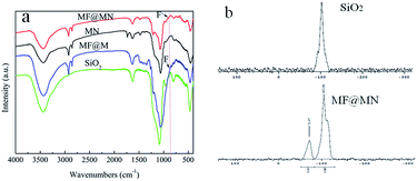 | ||
| Fig. 2 (a) The FT-IR spectra of MF@MN, MN, MF@M and SiO2, (b) the solid-state 29Si CP-MAS NMR spectra of SiO2 and MF@MN. | ||
The solid-state 29Si CP-MAS NMR spectra of SiO2 and MF@MN were shown in Fig. 2b. The Q-bands assigned to Si(–O–Si)x(OH)4−x could be clearly observed. The presence of Q3 and Q4 testified that the framework of mesoporous silica was unchanged.27,28 The intense signals for Q bands confirmed that the mesoporous silica was subjected to a high degree of condensation. Moreover, amphiphilic mesoporous silica with a large number of Si–OH was in favor of the successful grafting of organic silane. The presence of T-bands equivalent to Si(C)(–O–Si)x(OH)3−x in MF@MN indicated that TFPS and APTS had been incorporated in the mesoporous silica through covalent linkage.
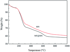
The TG curves of MF@MN and MN were exhibited in Fig. 3. The TG curves revealed that three stages of decomposition occurred for the mesoporous silica. When the temperature was below 160 °C, the weight loss was mainly owing to the physically adsorbed water. When the temperature was between 160 °C and 300 °C, the weight loss was assigned to the degradation of organic template. When the temperature was higher than 300 °C, the weight loss was mainly due to the decomposition of the grafted TFPS and APTS and the condensation dehydration of silica groups at high temperature. For the mesoporous silica MN, the weight loss was much less than MF@MN, which also confirmed the successful grafting of TFPS.
The pore structure and surface area of mesoporous silica were characterized by N2 adsorption–desorption. The type IV isotherms of both MF@MN and MN could be seen in Fig. 4a, but the hysteresis loop was not obvious when quaternary ammonium salt CTAC was used as the template in the synthesis of mesoporous silica. Compared with MN, the BET specific surface area of MF@MN dropped from 40 to 35 m2 g−1, the pore volume decreased from 0.111 to 0.103 cm3 g−1 and the pore size decreased from 2.5 to 2.2 nm, respectively. The above measured values of MF@MN and MN were all smaller than conventional mesoporous sieves without modification. It was mainly because the N2 adsorption–desorption measurements were performed at −196 °C, so organic silane TFPS and APTS grafted on mesoporous silica became hard and a certain channels were occupied. Perpendicularly oriented channels were observed in Fig. 4c.
 | ||
| Fig. 4 (a) The N2 adsorption–desorption isotherms, (b) the pore size distribution of MF@MN and MN, (c) the TEM image of MF@MN. | ||
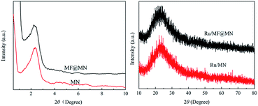
Fig. 5 showed the typical XRD patterns of MF@MN, MN, Ru/MF@MN and Ru/MN. The low-angle XRD patterns of MF@MN and MN exhibited one diffraction peak in the 2θ range of 2°–3°. The (100) reflection of amorphous silica confirmed the formation of hexagonal mesoporous structure. The diffraction peak of the amorphous silica was at 22.5° in high-angle XRD diffraction. However, the diffraction peak at 40° assigned to Ru nanoparticles was hardly observed. It may be due to the fact that the size of Ru nanoparticles was too small and Ru nanoparticles were dispersed uniformly on surface or in channels of mesoporous silica,29 which could be testified by the following TEM images.
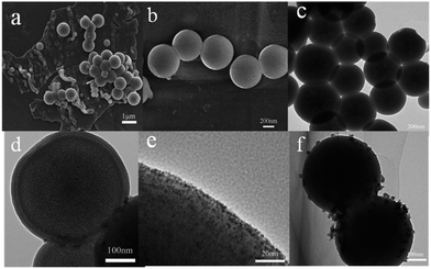
Fig. 6 showed the morphology of MF@MN and Ru nanoparticles. The spherical and sheet structure were coexistence when mesoporous silica was synthesized under vigorously stirring as shown in Fig. 6a. In addition, the phenomenon of concatenation among spherical mesoporous silica was observed as well. The mechanical force produced by vigorous stirring was in favor of contact between metastable state methyl orthosilicate TMOS and organic template CTAC, which resulted in the adhesion of nanospheres. The aggregates in emulsion were stretched into flakes or columns owing to the effect of shear stress.30 The synthetic conditions of amphiphilic mesoporous silica were optimized such as dispersion time of organic template, content of organic template, pH of synthetic system, temperature and stirring speed (Fig. S1†). Under the optimal conditions, only the uniform spherical mesoporous silica was obtained with an average diameter of 400 ± 50 nm as exhibited in Fig. 6b and c. The core–shell structure of spherical mesoporous silica was clearly observed in Fig. 6d and the average thickness of the shells was 20 nm or so.
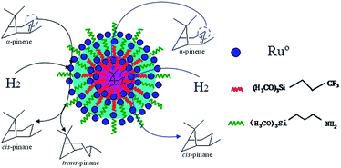
Scheme 1 depicted the formation of amphiphilic MF@MN and the structure of Ru/MF@MN catalyst. MF@MN contained hydrophobic core (MF) and hydrophilic shell (MN). As can be seen from Fig. 6e, Ru nanoparticles were uniformly immobilized on the surface of MF@MN with an average diameter of 1.8 nm (Fig. S2†). Fig. 6f was the TEM image of Ru/MF@MN0. The catalyst Ru/MF@MN0 was prepared by using MF@MN as carrier and Ru nanoparticles were anchored on such amphiphilic mesoporous silica without the assistance of ultrasonic. In Fig. 6f, the aggregates of Ru nanoparticles were obviously present, which indicated that ultrasonic was in favor of the dispersion of Ru nanoparticles.
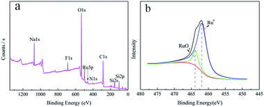
In order to deeply analyze the surface elemental composition of the Ru/MF@MN catalyst and valence state of Ru nanoparticles on the MF@MN, the catalyst was detected by XPS technology. These results were shown in Fig. 7. Two peaks centered at 688.5 eV and 402.8 eV in Fig. 7a were assigned to F 1s and N 1s, which indicated that organic silane TFPS and APTS had been grafted to the framework of mesoporous silica successfully. The electron binding energies of Ru 3P1/2, Ru 3P3/2 and Ru 3d5/2 were 484.5 eV, 462.5 eV and 280.4 eV, respectively, which were coincident with the standard XPS elemental map of Ru (484.5 eV, 462.0 eV and 280.2 eV). The enlarged region of Ru 3P3/2 was shown in Fig. 7b, the ratio of Ru (0) was 89.5%. 10.5% ruthenium oxide in Ru/MF@MN was probably due to the oxidation of Ru nanoparticles during the preparation of samples.31
3.2 The hydrogenation activity of various catalysts and the influence of solvents
The catalytic hydrogenation of α-pinene by various catalysts and the effects of solvents were systematically investigated under the same conditions. The results can be seen from Table 1.| Entry | Catalyst | Solvent | Conversion (%) | Selectivity (%) |
|---|---|---|---|---|
a Reaction conditions: 35 °C, 2 MPa H2, 500 rpm, 1 h, m (H2O)![[thin space (1/6-em)]](https://www.rsc.org/images/entities/char_2009.gif) : :![[thin space (1/6-em)]](https://www.rsc.org/images/entities/char_2009.gif) m (α-pinene) m (α-pinene)![[thin space (1/6-em)]](https://www.rsc.org/images/entities/char_2009.gif) : :![[thin space (1/6-em)]](https://www.rsc.org/images/entities/char_2009.gif) m (Ru/MF@MN) = 200 m (Ru/MF@MN) = 200![[thin space (1/6-em)]](https://www.rsc.org/images/entities/char_2009.gif) : :![[thin space (1/6-em)]](https://www.rsc.org/images/entities/char_2009.gif) 60 60![[thin space (1/6-em)]](https://www.rsc.org/images/entities/char_2009.gif) : :![[thin space (1/6-em)]](https://www.rsc.org/images/entities/char_2009.gif) 1. 1. |
||||
| 1 | Ru/C | H2O | 67.9 ± 0.1 | 98.7 ± 0.1 |
| 2 | Pd/C | H2O | 68.6 ± 0.5 | 87.8 ± 0.4 |
| 3 | Raney-Ni | H2O | 18.8 ± 0.4 | 96.2 ± 0.3 |
| 4 | Ru/SiO2 | H2O | 35.7 ± 0.2 | 98.5 ± 0.2 |
| 5 | Ru/MF@M | H2O | 33.1 ± 0.2 | 95.8 ± 0.1 |
| 6 | Ru/MN | H2O | 90.2 ± 0.1 | 98.5 ± 0.1 |
| 7 | Ru/MF@MN | H2O | 99.9 ± 0.1 | 98.8 ± 0.1 |
| 8 | Pd/MF@MN | H2O | 98.9 ± 0.4 | 80.0 ± 0.5 |
| 9 | Ru/MF@MN | C2H5OH | 28.2 ± 0.2 | 98.5 ± 0.1 |
| 10 | Ru/MF@MN | C7H16 | 27.0 ± 0.3 | 95.8 ± 0.2 |
| 11 | Ru/MF@MN | CH3COOC2H5 | 30.6 ± 0.1 | 99.0 ± 0.1 |
| 12 | Ru/MF@MN | — | 3.4 ± 0.2 | 98.9 ± 0.1 |
Compared to Raney-Ni and Pd/C, the catalytic activity and cis-pinane selectivity were the highest when Ru/C was used in catalytic hydrogenation of α-pinene (entries 1–3). So Ru was selected as the catalytic active species in the following experiments. The influence of organic functional groups grafted on the mesoporous silica for hydrogenation of α-pinene was studied (entries 4–7). The conversion of α-pinene was only 35.7% when SiO2 was the carrier. The catalyst Ru/SiO2 (entry 4) could not disperse uniformly in organic phase due to its inherent hydrophilicity, which resulted in poor activity of Ru/SiO2. When the mesoporous silica was only modified with TFPS (marked as MF@M), the catalytic efficiency of catalyst Ru/MF@M (entry 5) was also poor. It maybe result from the poor dispersion of Ru/MF@M in water phase because Ru/MF@M possesses strong hydrophobicity. Moreover, the brown solution was observed (Fig. 8a) after hydrogenation of α-pinene by Ru/MF@M. It indicated that a part of Ru nanoparticles leached into the product phase. When mesoporous silica was functionalized with hydrophilic APTS (marked as MN), the activity of hydrophilic catalyst Ru/MN (entry 6) was significantly improved and 90.2% α-pinene conversion was obtained. However, the catalytic activity of Ru/MN was still lower than that of Ru/MF@MN (entry 7). When mesoporous silica was modified with both hydrophobic TFPS and hydrophilic APTS (marked as MF@MN), the dispersibility of catalyst Ru/MF@MN in organic-aqueous biphasic system was markedly enhanced. Then the amphiphilic catalyst was applied in selective hydrogenation of α-pinene. The α-pinene conversion could reach as high as 99.9% and the selectivity for cis-pinane was 98.8%. In addition, the product phase was transparent and colorless after hydrogenation of α-pinene (Fig. 8a). It indicated that Ru nanoparticles existed steadily on the surface of amphiphilic MF@MN. For comparison purpose, Pd nanoparticles loaded on amphiphilic mesoporous silica were prepared by using Pd(C2H3O2)2 as metal precursor and denoted as Pd/MF@MN. The catalyst was also used in hydrogenation of α-pinene. 98.9% conversion was obtained, but the selectivity for cis-pinane was only 80.0% (entry 8). It testified the property of ruthenium was in favor of the selective hydrogenation of α-pinene compared to Pd species.
 | ||
| Fig. 8 (a) The product phase after hydrogenation of α-pinene, (b) the bubbles generated during the hydrogenation of α-pinene, (c) the formation mechanism of bubbles. | ||
The effect of different solvents on hydrogenation of α-pinene was also studied (entries 7, 9–12) when Ru/MF@MN was used as catalyst. The difference in catalytic performance was not obvious for organic medium. The conversion was only 30.0% or so when organic solvents were used. However, in water medium (entry 7), Ru/MF@MN exhibited the best activity and selectivity.
During hydrogenation of α-pinene, the uniform W/O (denoted as oil-in-water) type bubbles were observed (Fig. 8b). The catalysts acting as solid foaming agent could disperse uniformly in organic-aqueous biphase due to the amphipathy of mesoporous silica (Fig. 8c). The bubbles enlarged the contact area of the solid-liquid-gas triphase and the efficiency of hydrogenation was improved.32
Moreover, the “micelle-like” amphiphilic mesoporous silica might be regarded as the microreactors. The hydrophobic core increased the concentration of α-pinene and revealed high catalytic activity. The selectivity of cis-pinane could be improved probably owing to stereoselectivity attack from endo surface of α-pinene by catalyst (Scheme 2).33 In addition, water was non-poisonous and harmless for environment and the use of water as solvent was consistent with the environmentally-friendly concept.
When the reaction was performed without H2O, the catalytic activity of Ru/MF@MN was very poor, and the α-pinene conversion was only 3.4%. It was probably because bubbles and microreactors could not be formed absence of water.
3.3 Reaction kinetics research
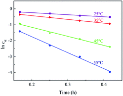
The kinetics data of hydrogenation of α-pinene over Ru/MF@MN in water were obtained within the temperature range of 298–328 K and under 2 MPa H2 at 600 rpm. When the stirring speed was more than 400 rpm, the conversion of α-pinene didn't increase with the increase of stirring speed (Fig. S3†). The effect of external diffusion can be ignored at 600 rpm and the reaction enters into the dynamic control area.34 Additionally, 2 MPa H2 is adequate for the hydrogenation of α-pinene and the catalytic system can be deemed to conform with pseudo-first-order kinetic model.35–37
 | (1) |
The concentration of α-pinene cα in eqn (1) is related with the initial concentration cα0 and the conversion of α-pinene x, which gave eqn (2).
| cα = cα0(1 − x) | (2) |
Hence eqn (1) could be replaced by the following eqn (3).
 | (3) |
After eqn (3) was integrated against time, eqn (4) was obtained
| −ln(1 − x) = kt | (4) |
The kinetics curves for hydrogenation of α-pinene at different temperatures were exhibited in Fig. 9. The linear relation between −ln(1 − x) and time could be observed, which testified that the reaction kinetics of α-pinene hydrogenation over Ru/MF@MN was in accordance with pseudo-first-order kinetic model. The slope values of 1.25 h−1, 2.33 h−1, 5.82 h−1, and 10.15 h−1 are corresponding to the rate constants of α-pinene hydrogenation at 25 °C, 35 °C, 45 °C and 55 °C, respectively.
The Arrhenius plot of α-pinene hydrogenation at different temperatures over Ru/MF@MN is presented (Fig. S4†). The apparent activation energy (Ea) can be figured out according to eqn (5):38
 | (5) |
As shown in eqn (5), the gas constant R is 8.314 J mol−1 K−1. Ea is calculated to be 57.0 kJ mol−1.
3.4 Catalyst recycling
The reusability of the Ru/MF@MN system was also investigated. The optimum reaction conditions for hydrogenation of α-pinene was 35 °C, 2 MPa H2, 1 h, m (H2O)![[thin space (1/6-em)]](https://www.rsc.org/images/entities/char_2009.gif) :
:![[thin space (1/6-em)]](https://www.rsc.org/images/entities/char_2009.gif) m (α-pinene)
m (α-pinene)![[thin space (1/6-em)]](https://www.rsc.org/images/entities/char_2009.gif) :
:![[thin space (1/6-em)]](https://www.rsc.org/images/entities/char_2009.gif) m (Ru/MF@MN) = 200
m (Ru/MF@MN) = 200![[thin space (1/6-em)]](https://www.rsc.org/images/entities/char_2009.gif) :
:![[thin space (1/6-em)]](https://www.rsc.org/images/entities/char_2009.gif) 60
60![[thin space (1/6-em)]](https://www.rsc.org/images/entities/char_2009.gif) :
:![[thin space (1/6-em)]](https://www.rsc.org/images/entities/char_2009.gif) 1 (Fig. S5†). After reaction, the catalyst was purged 3 runs by anhydrous ethanol. In addition, it was dried under vacuum at 50 °C for 4 h. The catalyst could be used directly in the next cycle. When m (H2O)
1 (Fig. S5†). After reaction, the catalyst was purged 3 runs by anhydrous ethanol. In addition, it was dried under vacuum at 50 °C for 4 h. The catalyst could be used directly in the next cycle. When m (H2O)![[thin space (1/6-em)]](https://www.rsc.org/images/entities/char_2009.gif) :
:![[thin space (1/6-em)]](https://www.rsc.org/images/entities/char_2009.gif) m (α-pinene)
m (α-pinene)![[thin space (1/6-em)]](https://www.rsc.org/images/entities/char_2009.gif) :
:![[thin space (1/6-em)]](https://www.rsc.org/images/entities/char_2009.gif) m (Ru/MF@MN) = 330
m (Ru/MF@MN) = 330![[thin space (1/6-em)]](https://www.rsc.org/images/entities/char_2009.gif) :
:![[thin space (1/6-em)]](https://www.rsc.org/images/entities/char_2009.gif) 100
100![[thin space (1/6-em)]](https://www.rsc.org/images/entities/char_2009.gif) :
:![[thin space (1/6-em)]](https://www.rsc.org/images/entities/char_2009.gif) 1, the conversion of α-pinene could reach 54.36 ± 0.1% and cis-pinane selectivity was 98.71 ± 0.1% even after 4 cycles. The invariable conversion was mainly due to the coordination between amino group in amphiphilic shell and Ru nanoparticles. The conversion of α-pinene decreased to 45.92% after six cycles. The TEM and XRD characterization of amphiphilic mesoporous silica after six cycles were shown in Fig. 10b and c. It was observed that the morphology and structure of the mesoporous silica were nearly unchanged. The decline of α-pinene conversion was probably owing to the leaching of Ru nanoparticles. Compared to the fresh catalysts, the loss of Ru nanoparticles was 0.13% measured by ICP-AES analysis after six cycles. It was mainly because APTS fell off from hydrophilic shell when catalyst was reused. The loss of nitrogen element was 0.35% according to the results of elemental analysis. The selectivity for cis-pinane was almost unchanged, which perhaps was attributed to the property of Ru and the shape-selective catalysis of amphiphilic MF@MN.
1, the conversion of α-pinene could reach 54.36 ± 0.1% and cis-pinane selectivity was 98.71 ± 0.1% even after 4 cycles. The invariable conversion was mainly due to the coordination between amino group in amphiphilic shell and Ru nanoparticles. The conversion of α-pinene decreased to 45.92% after six cycles. The TEM and XRD characterization of amphiphilic mesoporous silica after six cycles were shown in Fig. 10b and c. It was observed that the morphology and structure of the mesoporous silica were nearly unchanged. The decline of α-pinene conversion was probably owing to the leaching of Ru nanoparticles. Compared to the fresh catalysts, the loss of Ru nanoparticles was 0.13% measured by ICP-AES analysis after six cycles. It was mainly because APTS fell off from hydrophilic shell when catalyst was reused. The loss of nitrogen element was 0.35% according to the results of elemental analysis. The selectivity for cis-pinane was almost unchanged, which perhaps was attributed to the property of Ru and the shape-selective catalysis of amphiphilic MF@MN.
4. Conclusions
The amphiphilic mesoporous silica MF@MN has been prepared by one-step synthesis. A variety of characterizations testify that TFPS and APTS have been successfully grafted on the framework of mesoporous silica. With the assistance of ultrasonic wave, Ru nanoparticles are uniformly anchored on the surface of amphiphilic mesoporous silica. The Ru/MF@MN catalyst is applied in the selective hydrogenation of α-pinene in water medium. Under the optimum reaction conditions (35 °C, 2 MPa H2, 1 h, m (H2O)![[thin space (1/6-em)]](https://www.rsc.org/images/entities/char_2009.gif) :
:![[thin space (1/6-em)]](https://www.rsc.org/images/entities/char_2009.gif) m (α-pinene)
m (α-pinene)![[thin space (1/6-em)]](https://www.rsc.org/images/entities/char_2009.gif) :
:![[thin space (1/6-em)]](https://www.rsc.org/images/entities/char_2009.gif) m (Ru/MF@MN) = 200
m (Ru/MF@MN) = 200![[thin space (1/6-em)]](https://www.rsc.org/images/entities/char_2009.gif) :
:![[thin space (1/6-em)]](https://www.rsc.org/images/entities/char_2009.gif) 60
60![[thin space (1/6-em)]](https://www.rsc.org/images/entities/char_2009.gif) :
:![[thin space (1/6-em)]](https://www.rsc.org/images/entities/char_2009.gif) 1), the conversion can reach 99.9% and 98.9% of α-pinene is converted to cis-pinane. The formation of uniform W/O type bubbles in the process of α-pinene hydrogenation can enlarge the contact area of the solid-liquid-gas triphase and thus improve the reaction efficiency. The “micelle-like” amphiphilic mesoporous silica can be regarded as the microreactors. Their hydrophobic cores can increase the concentration of α-pinene and be beneficial for achieving high catalytic activity. Furthermore, the α-pinene conversion and selectivity for cis-pinane are unchanged even after 4 cycles, exhibiting good stability.
1), the conversion can reach 99.9% and 98.9% of α-pinene is converted to cis-pinane. The formation of uniform W/O type bubbles in the process of α-pinene hydrogenation can enlarge the contact area of the solid-liquid-gas triphase and thus improve the reaction efficiency. The “micelle-like” amphiphilic mesoporous silica can be regarded as the microreactors. Their hydrophobic cores can increase the concentration of α-pinene and be beneficial for achieving high catalytic activity. Furthermore, the α-pinene conversion and selectivity for cis-pinane are unchanged even after 4 cycles, exhibiting good stability.
Conflicts of interest
There are no conflicts to declare.Acknowledgements
This research was financially supported by the National Natural Science Foundation of China (No. 31270615) and the Taishan Scholars Projects of Shandong Province (ts 201511033).References
- T. Brose, W. Pritzkow and G. Thomas, J. Prakt. Chem., 1992, 334, 403–409 CrossRef CAS.
- G. Lauterbach and W. Pritzkow, J. Prakt. Chem./Chem.-Ztg., 1995, 337, 416–417 CrossRef CAS.
- S. Ren, J. Qiu, C. Wang, B. Xu, Y. Fan and Y. Chen, Chin. J. Inorg. Chem., 2007, 23, 1021–1028 CAS.
- V. A. Semikolenov, I. I. Ilyna and I. L. Simakova, Appl. Catal., A, 2001, 211, 91–107 CrossRef CAS.
- Y. Li, C. G. Pan, W. F. Han, H. F. Chai and H. Z. Liu, Catal. Today, 2011, 174, 97–105 CrossRef CAS.
- L. Wang, H. Guo, X. Chen, Q. Chen, X. Wei, Y. Ding and B. Zhu, Catal. Sci. Technol., 2015, 5, 3340–3351 CAS.
- M. Opanasenko, P. Stepnicka and J. Cejka, RSC Adv., 2014, 4, 65137–65162 RSC.
- B. I. Mengyu and T. Zeng, J. Nanjing For. Univ., 2003, 511, 1–15 Search PubMed.
- X. Yang, S. W. Liu, C. X. Xie, S. T. Yu and F. S. Liu, Chin. J. Catal., 2011, 32, 643–646 CAS.
- A. Milewska, A. M. B. Osuna, I. M. Fonseca and M. N. D. Ponte, Green Chem., 2005, 726–732 RSC.
- Y. Yang, X. Liu, D. Yin, Z. Zhang, D. Lei and J. Yang, Russ. J. Appl. Chem., 2015, 26, 333–334 CAS.
- L. Wang, H. Q. Guo, X. P. Chen, Y. Y. Huang and P. P. Zhang, React. Kinet., Mech. Catal., 2015, 114, 639–660 CrossRef CAS.
- Y. Yang, X. Liu, D. Yin, Z. Zhang, D. Lei and J. Yang, J. Ind. Eng. Chem., 2015, 26, 333–334 CrossRef CAS.
- S. Noël, B. Léger, A. Ponchel, K. Philippot, A. Denicourt-Nowicki, A. Roucoux and E. Monflier, Catal. Today, 2014, 235, 20–32 CrossRef.
- A. Denicourt-Nowicki, A. Ponchel, E. Monflier and A. Roucoux, Dalton Trans., 2007, 48, 5714–5719 RSC.
- S. L. Hou, X. Y. Wang, C. R. Huang, C. X. Xie and S. T. Yu, Catal. Lett., 2016, 146, 1–7 CrossRef.
- S. L. Hou, C. X. Xie, F. L. Yu, B. Yuan and S. T. Yu, RSC Adv., 2016, 6, 54806–54811 RSC.
- Y. Liu, L. Li, S. W. Liu, C. X. Xie and S. T. Yu, J. Mol. Catal. A: Chem., 2016, 424, 269–275 CrossRef CAS.
- Z. Li, R. Yu, J. Huang, Y. Shi, D. Zhang, X. Zhong, D. Wang, Y. Wu and Y. Li, Nat. Commun., 2015, 6, 8248–8255 CrossRef CAS PubMed.
- B. Ghosh, S. Hazra, B. Naik and N. Ghosh, J. Nanosci. Nanotechnol., 2015, 15, 6516–6523 CrossRef PubMed.
- A. Selka, N. Levesque, D. Foucher, O. Clarisse, F. Chemat and M. Touaibia, Org. Process Res. Dev., 2017, 21, 60–64 CrossRef CAS.
- S. B. Qiu, Y. Xu, Y. J. Weng, L. L. Ma and T. J. Wang, Catalysts, 2016, 6, 134–149 CrossRef.
- M. Ahmed and A. Sakthivel, J. Mol. Catal. A: Chem., 2016, 424, 85–90 CrossRef CAS.
- L. Fu, S. Li, Z. Han, H. Liu and H. Yang, Chem. Commun., 2014, 50, 10045–10048 RSC.
- F. W. Zhang and H. Q. Yang, Catal. Sci. Technol., 2014, 5, 572–577 Search PubMed.
- X. F. Li, W. J. Zhang, L. M. Zhang and H. Q. Yang, Chin. J. Catal., 2013, 34, 1192–1200 CrossRef CAS.
- S. Li, X. Jiao and H. Yang, Langmuir, 2013, 29, 1228–1237 CrossRef CAS PubMed.
- H. X. Wang, H. Q. Yang, H. R. Liu, Y. H. Yu and H. C. Xin, Langmuir, 2013, 29, 6687–6696 CrossRef CAS PubMed.
- F. W. Zhang, S. Chen, H. Li, X. M. Zhang and H. Q. Yang, RSC Adv., 2015, 5, 102811–102817 RSC.
- D. Liang, Y. Wang, Y. D. Bai and R. F. Li, Chin. J. Inorg. Chem., 2010, 26, 1031–1038 CAS.
- S. L. Hou, C. X. Xie, H. Zhong and S. T. Yu, RSC Adv., 2015, 5, 89552–89558 RSC.
- J. W. Yang, J. M. Duan, F. Daniel and J. Ralston, J. Phys. Chem. B, 2003, 107, 6139–6147 CrossRef CAS.
- J. M. Brown, A. E. Derome, G. D. Hughes and P. K. Monaghan, Aust. J. Chem., 1992, 45, 143–153 CrossRef CAS.
- I. L. Simakova, Y. L. Solkina, I. Deliy, A. Wärn, M. Johan and Y. Dmitry, Appl. Catal., A, 2009, 356, 216–224 CrossRef CAS.
- R. Begum, K. Naseem, E. Ahmed, A. Sharif and Z. H. Farooqi, Colloids Surf., A, 2016, 511, 17–26 CrossRef CAS.
- F. W. Zhang, S. Chen and H. Li, RSC Adv., 2015, 5, 102811–102817 RSC.
- H. Wang, Z. Li and Y. Liu, Green Chem., 2009, 11, 1568–1575 RSC.
- Z. Farooqi, R. Begum, K. Naseem, U. Rubab, M. Usman, A. Khan and A. Ijaz, Russ. J. Phys. Chem. A, 2016, 90, 2600–2608 CrossRef CAS.
Footnote |
| † Electronic supplementary information (ESI) available. See DOI: 10.1039/c7ra09865k |
| This journal is © The Royal Society of Chemistry 2017 |

