
 Open Access Article
 This Open Access Article is licensed under a
 Creative Commons Attribution 3.0 Unported Licence
A transparent 3D printed device for assembling droplet hydrogel bilayers (DHBs)†
Abigail de Bruina,
Mark S. Friddin *ab,
Yuval Elaniab,
Nicholas J. Brooksab,
Robert V. Lawab,
John M. Seddonab and
Oscar Ces*ab
*ab,
Yuval Elaniab,
Nicholas J. Brooksab,
Robert V. Lawab,
John M. Seddonab and
Oscar Ces*ab
aDepartment of Chemistry, Imperial College London, Exhibition Road South Kensington, London, SW7 2AZ, UK. E-mail: m.friddin@imperial.ac.uk
bInstitute of Chemical Biology, Imperial College London, Exhibition Road South Kensington, London, SW7 2AZ, UK. E-mail: o.ces@imperial.ac.uk
First published on 11th October 2017
Abstract
We report a new approach for assembling droplet hydrogel bilayers (DHBs) using a transparent 3D printed device. We characterise the transparency of our platform, confirm bilayer formation using electrical measurements and show that single-channel recordings can be obtained using our reusable rapid prototyped device. This method significantly reduces the cost and infrastructure required to develop devices for DHB assembly and downstream study.
Lipid bilayers formed between water droplets in oil have become well-established for reconstituting ion channels1 and transporters,2 for screening channel blockers,3 and for studying the biophysical properties of membranes.4 These model architectures, coined droplet interface bilayers (DIBs) by Bayley and co-workers,1,5 are formed at the interface of two lipid-coated water droplets manipulated into contact inside a well of oil. Lipids are typically dissolved into the oil (Fig. 1A), or supplied directly to the droplet as a dispersion of small unilamellar vesicles. While DIBs are both versatile and scalable,6,7 the requirement to carefully manipulate droplets into contact can be circumvented by replacing one of the droplets with a hydrogel surface (Fig. 1B) to form a droplet-hydrogel bilayer (DHB).8
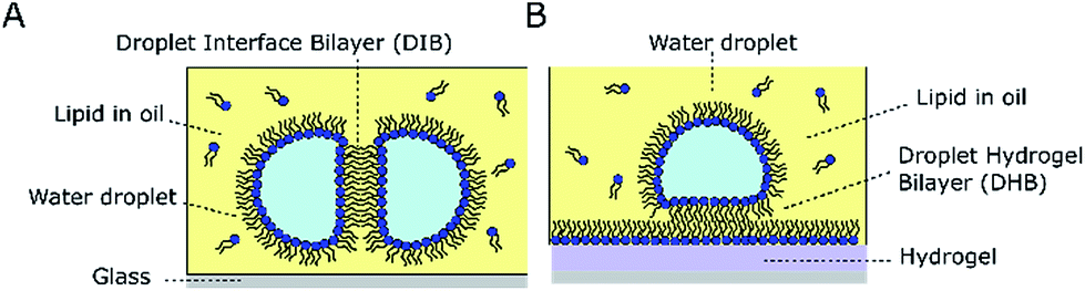 | ||
| Fig. 1 Droplet Interface Bilayers (DIBs) and Droplet Hydrogel Bilayers (DHBs). (A) DIBs are formed at the interface of two lipid-monolayer coated water droplets in a well of lipid–oil. (B) DHBs are formed at the interface of a lipid-monolayer coated water droplet and a lipid-coated hydrogel surface. Bilayer visualisation is easier in DHBs as the bilayer is positioned parallel to the surface. | ||
DHBs have been used to reconstitute a range of potassium channels9 and, due to reduced substrate/bilayer interactions, are reported to have a ca. 20-fold higher lateral diffusion coefficient compared to supported lipid bilayers,10 rendering DHBs more representative of free-standing membranes. With the bilayer positioned parallel to the optical plane (as opposed to perpendicular to it, as with DIBs) DHBs are better suited to optical characterisation using TIRF microscopy,10 which can enable the simultaneous acquisition of optical and electrical measurements,11 and can also be employed to screen an array of droplets containing protein pores.12 DHBs can also be engineered to exhibit a range of tuneable bilayer properties; the size and protein concentration of the DHB can be adjusted by manipulating the droplet-surface contact area,13 bilayer tension can be generated by stretching the droplet monolayer,14 and the lipid composition of the membrane can be modified by titrating lipids into the oil phase.15
To access these desirable properties, the fabrication of devices for assembling DHBs typically involves spin-coating glass coverslips with agarose and micromachining acrylic devices,16 requiring specialist technicians, equipment and infrastructure. This presents a bottleneck that hinders the adoption of this platform by researchers working in other fields where such facilities may not be freely available. 3D printing these platforms provides a direct route to circumventing this barrier to access by minimising the facilities required for device fabrication, while also reducing the cost, build time, and lead-time between device generations. These factors coupled with the open-source sharing of designs, the accessibility of affordable 3D printers capable of printing complex parts and the availability of transparent materials are driving a paradigm shift in the fabrication of microfluidic platforms away from micromachining and soft lithography and toward rapid prototyping solutions.17,18
Here, we report that the traditional approach to DHB assembly can be simplified using a low-cost 3D printer to manufacture transparent devices for assembling DHBs on top of pre-cast hydrogel sheets. We characterise the transparency of two commercially available 3D printed materials (made with different printers), confirm that DHBs can be successfully assembled by our 3D printed platform using optical and electrical measurements, and demonstrate that these bilayers can be used to reconstitute individual proteins by showing single-channel measurements of the pore forming protein alpha haemolysin (αHL). Our method is simple, reusable, inexpensive, cleanroom-free, and could vastly extend the reach of the DHB platform, especially given the speed at which new generations of each device can be made.
Lipid films were prepared using 1,2-diphytanoyl-sn-glycero-3-phosphocholine (DPhPC, Avanti Polar Lipids) which was dissolved in chloroform, evaporated under a stream of nitrogen and dried under vacuum overnight. The film was dissolved to a final concentration of 8.7 mg ml−1 in hexadecane (Sigma Aldrich) and heated at 60 °C for two hours to ensure complete dissolution of the lipids. Hydrogel sheets were prepared using 5% (w/v) low-melt agarose (Sigma Aldrich) in DI water. Molten agarose was poured into a mould made from 380 µm thick pieces of acrylic shim (RS components) which was compressed in between two 5 mm thick pieces of acrylic (see ESI†). All 3D printed parts were designed in Autodesk Inventor and imported as .STL files into Cura (Ultimaker) for printing in clear PLA (Faberdashery, Crystal Clear 3 mm) with an Ultimaker 2. The material was printed at 30 mm s−1 with a layer thickness of 0.05 mm, an infill value of 100% and an extrusion temperature of 215 °C as described previously.19 VeroClear-RGD810 was printed with an EDEN 250 (Stratasys) using the default settings. Our device consisted of a replaceable hydrogel sheet secured using magnets between a 3D printed base and a gasket containing a well (ϕ = 10 mm) as outlined in Fig. 2. The base layer contained a fluidic channel (2 mm wide) that served to keep the hydrogel sheet hydrated at all times, and the well was filled with lipid–oil prior to use (see Fig. 2).
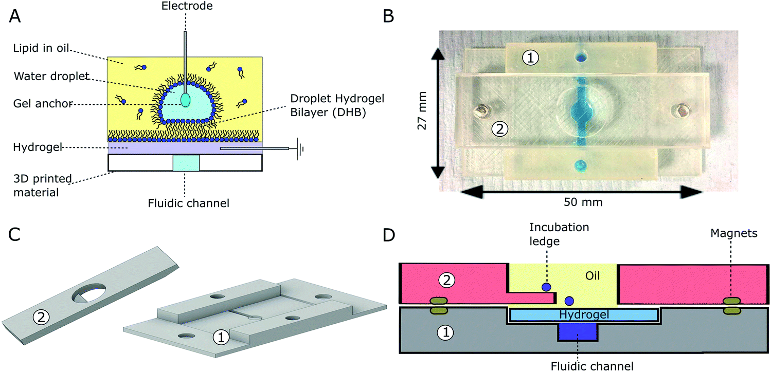 | ||
| Fig. 2 Transparent 3D printed device for DHB assembly. (A) Schematic of bilayer formation and current measurements via agar coated Ag/AgCl electrodes. (B) Photograph of 3D printed device with blue dye in the fluidic channel. A hydrogel sheet is sandwiched between components 1 & 2, which are held together using magnets. (C) 3D CAD image of the two 3D printed components (D) schematic of device cross section. | ||
Transparency is a prerequisite property for successfully monitoring bilayer assembly using microscopy. To determine how material thickness effects the transparency of the transparent PLA, we printed slides with thicknesses ranging from 0.25–3 mm and compared the mean fluorescence intensity of 1 µl droplets containing 0.1 mM calcein in buffer (500 mM KCl, 25 mM Tris–HCl, pH 7.4). Slides were also printed in VeroClear-RGD810 using an Eden 250 Polyjet Printer for comparison. Measurements were obtained using an inverted microscope inside wells filled with hexadecane (see ESI†). The data in Fig. 3A shows a general decrease in the average fluorescence intensity of the droplets as the thickness of each material increases however under these conditions the effect seems negligible for surfaces less than 1 mm thick. No signal was observed when the droplets contained pure buffer and no calcein (data not shown). We subsequently used 1 mm thick slides to screen droplets containing a range of calcein concentrations on both material types in Fig. 3B. This revealed an overall concentration-dependant increase in the average signal intensity for calcein concentrations ranging from 0.1 mM to 1.0 mM. Given the relatively short exposure time of 30 ms, these measurements highlight the ability to detect small concentrations of fluorescent dyes through both 3D printed materials. To characterise the transparency of these substrates to different wavelengths of light we used an Ocean Optics Flame miniature spectrometer in combination with a light source to perform transmittance measurements. Here we define optical transmittance as a percentage of what was obtained from a blank measurement with nothing in the light-path. All data was normalised by subtracting the background measured without illumination. We found that the optical transmittance for 2 mm thick samples was 55% or higher for both the VeroClear (Fig. 3C) and PLA (Fig. 3D) samples across the whole visible spectrum. Our plots suggest that the VeroClear material is more transparent than the PLA, exhibiting a transmittance of over 90% above 480 nm. Both materials also transmitted over 25% down to 350 nm, with the PLA transmitting slightly more light in the near-UV (see ESI†). Our measurements confirm that both 3D printed substrates can be used in combination with all common fluorophores used for fluorescence microscopy, which could have significant implications for studying DIBs and DHBs on 3D printed surfaces and devices.
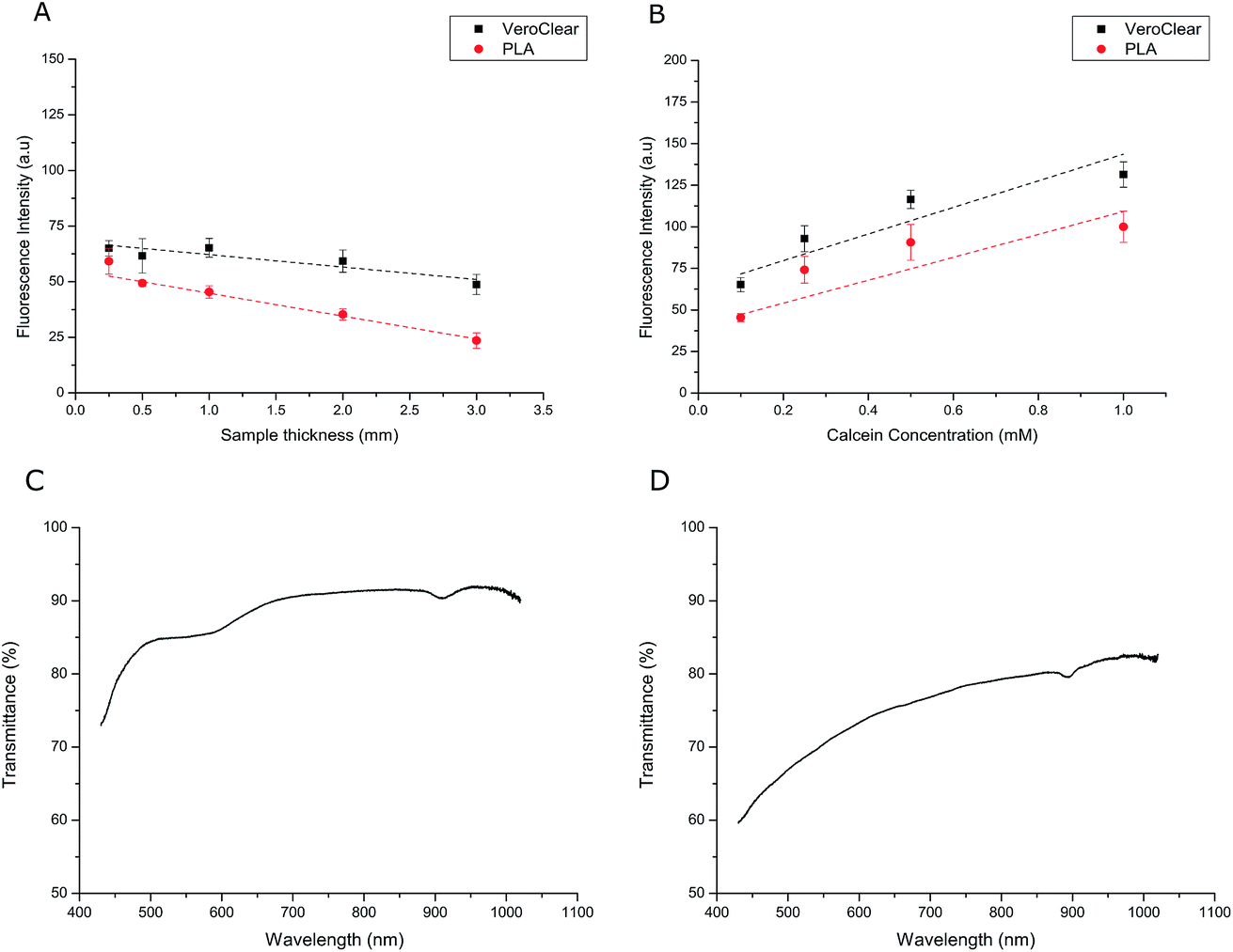 | ||
| Fig. 3 Transparency measurements. (A) The effect of 3D printed substrate thickness on its transparency using 1 µl 0.1 mM calcein droplets (n ≥ 3). (B) Fluorescence intensity of 1 µl droplets with varying calcein concentrations on different materials (n ≥ 3). (C) and (D) Plots of optical transmittance of VeroClear (C) and PLA (D) as a function of wavelength using 2 mm thick samples. | ||
To demonstrate that DHBs could be assembled on our device we positioned a 1 µl droplet of buffer (500 mM KCl, 25 mM Tris–HCl, pH 7.4) onto a ledge incorporated into our 3D printed gaskets. The droplet was left to incubate for 20 minutes in 8.7 mg ml−1 DPhPC in hexadecane prior to being relocated onto the hydrogel surface with a needle. Fig. 4A shows brightfield micrographs of a typical droplet loaded onto one of our hydrogel surfaces and imaged through the 3D printed-hydrogel assembly using an inverted microscope. The images show the gradual appearance of a black patch at the droplet-surface interface, which we attribute to the formation of a DHB. Consistent with a Black/Bilayer Lipid Membranes (BLMs), the DHB appears black in incident light due to the destructive interference of light reflecting off the nanometre thick membrane leaflets.20 This, together with the apparent change in the droplet-surface contact angle, strongly implies the presence of a bilayer.
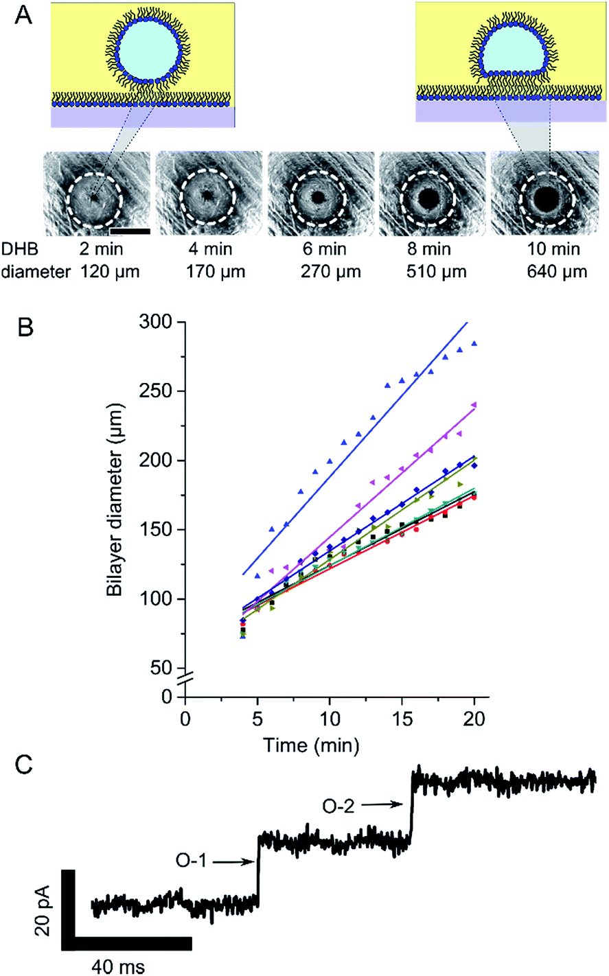 | ||
| Fig. 4 DHB characterisation. (A) Brightfield micrographs of DHB formation. The images show the appearance a black patch that increases in size. Scale bar = 1 mm, exposure time = 100 ms. White circles show approximate location of droplet (B) graph of bilayer area growth over time for 7 bilayers, as determined by capacitance measurements. The different shapes and colours represent separate measurements (C) single channel measurement of αHL reconstituted into our DHBs. Two single-channel openings (O-1 and O-2) are shown, each leading to ca. 20 pA increase in current. | ||
To provide further evidence of bilayer formation we also performed bilayer capacitance measurements by inserting the agar coated tips of Ag/AgCl electrodes (Goodfellow) either side of the bilayer using micromanipulators (Thorlabs). A 1 µl droplet of buffer was lowered into the well of lipid oil via an Ag/AgCl electrode and placed on to the ledge for 20 minutes prior to being transferred to the hydrogel surface. A second Ag/AgCl electrode connected to ground was positioned inside the fluidic channel (see Fig. 2A). The electrodes were connected to an Axon AxoPatch 200B Amplifier via a CV-203BU headstage (Molecular Devices) and data acquisition was controlled by a PC using an Axon Digidata 1440A digitiser (Molecular Devices). Bilayer capacitance was recorded by applying a linear voltage ramp where the measured current response (e.g., 500 pA) can be interpreted as the bilayer capacitance (e.g., 500 pF) when dV/dT = 1, as I = dV/dT × C. Bilayer area can be approximated using a specific capacitance of 0.5 µF cm−2.21,22 Capacitance measurements obtained for 6 independent DHBs are shown in Fig. 4B, which both confirm the presence of a DHB and reveal a gradual increase in bilayer diameter. This is similar to what was observed for DHBs formed on an optical microscope in Fig. 4A except these bilayers appear to be slightly smaller in size, most likely due to a reduction in the droplet-surface contact area due to the presence of the coated Ag/AgCl electrode. In our experiments, we found that bilayers from ca. 100 µm in diameter could be reliably detected using brightfield microscopy, while capacitance measurements could be used to detect bilayers down to 70 µm in diameter (corresponding to a bilayer capacitance of ca. 20 pF). These values are comparable to typical aperture-suspended lipid bilayers1 and could be significantly improved using more elaborate setups.
To show that proteins could be reconstituted into DHBs assembled using our platform, we introduced 50 ng µl−1 αHL (Sigma Aldrich) into our droplets and measured the bilayer current under a holding potential of 100 mV. Under these conditions we observed discrete openings (Fig. 3C) of ca. 20 pA in the baseline current (n = 3), which are indicative of αHL both in terms of the amplitude of the openings and by the absence of gating events.23 Our results suggest that our membranes have similar properties to DHBs assembled on conventional substrates. While control over bilayer dynamics might be improved with future device generations, our findings emphasise the power of rapid prototyping to eliminate barriers to device fabrication and present a significant step towards democratising the DHB platform.
Conclusions
Our results confirm that DHBs can be successfully assembled on a reusable rapid prototyped platform consisting of transparent 3D parts and a cast hydrogel sheet. Our approach requires no specialist engineering infrastructure and can be used for fluorescence studies or for single-channel electrophysiology. With recent developments in light sensitive DHB networks,24 in encapsulating communicating droplets25 and with targeting individual droplets using light26 we envisage that the wide accessibility and adaptability of our approach will extend the reach of DHBs and enable future generations of 3D printed devices to harness the potential of individually addressable and interconnected membrane compartments designed to replicate natural biological pathways.Conflicts of interest
There are no conflicts to declare.Acknowledgements
The authors would like to thank Lee Tooley for his assistance with preparing the hydrogel moulds. This work was supported by the EPSRC via grants EP/J017566/1 and EP/N016998/1. All data created during this research are openly available from Imperial College at http://www.imperial.ac.uk/membranebiophysics.References
- H. Bayley, B. Cronin, A. Heron, M. A. Holden, W. L. Hwang, R. Syeda, J. Thompson and M. Wallace, Mol. BioSyst., 2008, 4, 1191–1208 RSC.
- H. E. Findlay, N. J. Harris and P. J. Booth, Sci. Rep., 2016, 6, 39349 CrossRef CAS PubMed.
- R. Syeda, M. A. Holden, W. L. Hwang and H. Bayley, J. Am. Chem. Soc., 2008, 130, 15543–15548 CrossRef CAS PubMed.
- N. E. Barlow, E. Smpokou, M. S. Friddin, R. Macey, I. R. Gould, C. Turnbull, A. J. Flemming, N. J. Brooks, O. Ces and L. M. Barter, Biomicrofluidics, 2017, 11, 024107 CrossRef CAS PubMed.
- T. Trantidou, M. Friddin, Y. Elani, N. J. Brooks, R. V. Law, J. M. Seddon and O. Ces, ACS Nano, 2017, 11(7), 6549–6565 CrossRef CAS PubMed.
- M. A. Holden, D. Needham and H. Bayley, J. Am. Chem. Soc., 2007, 129, 8650–8655 CrossRef CAS PubMed.
- G. Villar, A. D. Graham and H. Bayley, Science, 2013, 340, 48–52 CrossRef CAS PubMed.
- A. J. Heron, J. R. Thompson, A. E. Mason and M. I. Wallace, J. Am. Chem. Soc., 2007, 129, 16042–16047 CrossRef CAS PubMed.
- S. Leptihn, J. R. Thompson, J. C. Ellory, S. J. Tucker and M. I. Wallace, J. Am. Chem. Soc., 2011, 133, 9370–9375 CrossRef CAS PubMed.
- J. R. Thompson, A. J. Heron, Y. Santoso and M. I. Wallace, Nano Lett., 2007, 7, 3875–3878 CrossRef CAS PubMed.
- A. J. Heron, J. R. Thompson, B. Cronin, H. Bayley and M. I. Wallace, J. Am. Chem. Soc., 2009, 131, 1652–1653 CrossRef CAS PubMed.
- O. K. Castell, J. Berridge and M. I. Wallace, Angew. Chem., Int. Ed., 2012, 51, 3134–3138 CrossRef CAS PubMed.
- L. C. M. Gross, O. K. Castell and M. I. Wallace, Nano Lett., 2011, 11, 3324–3328 CrossRef CAS PubMed.
- K. R. Rosholm, M. A. B. Baker, P. Ridone, Y. Nakayama, P. R. Rohde, L. G. Cuello, L. K. Lee and B. Martinac, Sci. Rep., 2017, 7, 45180 CrossRef CAS PubMed.
- J. S. H. Danial, B. Cronin, C. Mallik and M. I. Walllace, Soft Matter, 2017, 13, 1788–1793 RSC.
- S. Leptihn, O. K. Castell, B. Cronin, E.-H. Lee, L. C. M. Gross, D. P. Marshall, J. R. Thompson, M. Holden and M. I. Wallace, Nat. Protoc., 2013, 8, 1048–1057 CrossRef CAS PubMed.
- N. Bhattacharjee, A. Urrios, S. Kang and A. Folch, Lab Chip, 2016, 16, 1720–1742 RSC.
- S. Waheed, J. M. Cabot, N. P. Macdonald, T. Lewis, R. M. Guijt, B. Paull and M. C. Breadmore, Lab Chip, 2016, 16, 1993–2013 RSC.
- A. J. L. Morgan, L. Hidalgo San Jose, W. D. Jamieson, J. M. Wymant, B. Song, P. Stephens, D. A. Barrow and O. K. Castell, PLoS One, 2016, 11, e0152023 Search PubMed.
- H. T. Tien, S. Carbone and E. A. Dawidowicz, Nature, 1966, 212, 718–719 CrossRef CAS.
- S. Aghdaei, M. E. Sandison, M. Zagnoni, N. G. Green and H. Morgan, Lab Chip, 2008, 8, 1617–1620 RSC.
- M. S. Friddin, H. Morgan and M. R. de Planque, Biomicrofluidics, 2013, 7, 014108 CrossRef PubMed.
- G. Villar, A. J. Heron and H. Bayley, Nat. Nanotechnol., 2011, 6, 803–808 CrossRef CAS PubMed.
- V. Restrepo Schild, M. J. Booth, S. J. Box, S. N. Olof, K. R. Mahendran and H. Bayley, Sci. Rep., 2017, 7, 46585 CrossRef CAS PubMed.
- M. Bayoumi, H. Bayley, G. Maglia and K. T. Sapra, Sci. Rep., 2017, 7, 45167 CrossRef CAS PubMed.
- M. J. Booth, V. Restrepo Schild, S. J. Box and H. Bayley, Sci. Rep., 2017, 7, 9315 CrossRef PubMed.
Footnote |
| † Electronic supplementary information (ESI) available. See DOI: 10.1039/c7ra09406j |
| This journal is © The Royal Society of Chemistry 2017 |