 Open Access Article
Creative Commons Attribution 3.0 Unported Licence
Self-crosslink assisted synthesis of 3D porous branch-like Fe3O4/C hybrids for high-performance lithium/sodium-ion batteries†
Ning Wang a,
Qinglei Liu*a,
Yue Lia,
Jichao Chenb,
Jiajun Gua,
Wang Zhanga and
Di Zhanga
aState Key Laboratory of Metal Matrix Composites, Shanghai Jiao Tong University, 800 Dongchuan Road, Shanghai, 200240, P. R. China. E-mail: liuqinglei@sjtu.edu.cn; Fax: +86 21 34202634; Tel: +86 21 34202634
bCRRC Industrial Institute Co., Ltd, China
First published on 27th October 2017
Abstract
A facile and effective self-crosslink assisted strategy is developed to fabricate 3D porous branch-like Fe3O4/C hybrids as high-performance anode materials for lithium ion batteries (LIBs) and sodium ion batteries (NIBs). Trivalent iron ions (Fe3+) are used to directly crosslink with biopolymer alginate to form nanoscale branch-like Fe-alginate hybrid nanostructures, which are converted to porous Fe3O4/C hybrids via a simple carbonization process. The resulting hybrids feature ultrafine active nanoparticles (∼5 nm), wrapping by thin graphitic layers, hierarchically nanoscale porous channels, and interconnected robust graphitic frameworks. Applying these in the anodes of LIBs, these structural features enable the hybrids to deliver high capacities of 974 and 570 mA h g−1 at 0.1 and 2 A g−1, respectively, and excellent cyclic stability with capacity retention of 98% after 200 cycles at 0.1 A g−1. In NIBs, reasonable capacities of 339 and 138 mA h g−1 are obtained at 0.05 and 5 A g−1, respectively. The high performance demonstrates the promising potential of the hybrids in next generation anodes for LIBs and NIBs.
1. Introduction
Li-ion batteries (LIBs) have been widely used in consumer electronics and electric vehicles because of their high energy density, long cycle lifespan and environmental friendliness.1–3 However, the ever growing huge demand for electrical energy storage (EES) devices, as well as the limited reserves and the relatively high cost of lithium, make the future of LIBs very challenging. To alleviate these problems, Na-ion batteries (NIBs), as alternatives for LIBs, are now drawing increasing attention from scientists, due to the analogous electrochemical properties of sodium and lithium, but much more natural abundance and lower cost of sodium (∼103 the reserve and ∼1/20 the price of lithium).4–6 To meet the huge commercial requirements, both LIBs and NIBs need to improve their specific capacities and cycling life. As the performance of batteries are mostly determined by the electrode materials, developing high-performance electrode materials available for both LIBs and NIBs are of great importance.During the past two decades, various of electrode materials including porous carbons,7–11 metal oxides like SnO2,12–15 MnO2,16–18 Fe3O4,19,20 Co3O4,21,22 and other materials23–27 have been investigated. Among these reported materials, Fe3O4 has been considered as one of the most promising anode materials for LIBs and NIBs, because of its high theoretical capacity (926 mA h g−1 for both LIBs and NIBs), nontoxic nature, earth abundance and low cost.28–33 However, when applied in practical use, Fe3O4-based anode materials usually suffer from severe volume expansion and particle pulverization during charge–discharge cycling, which lead to low rate performance and poor cycling stability.34–36 To achieve higher rate and better cycling performance, various strategies have been developed to improve the structural integrity and electronic conductivity of Fe3O4-based electrode materials. So far, the most recognized strategies are to optimize the particle size of Fe3O4 (ref. 37–39) and to induce porous carbon materials as conductive frameworks.20,34–36,40,41 For example, in the field of LIBs, Chen and coworkers42 reported a two-step method to encapsulate Fe3O4 nanoparticles (∼5 nm) in mesoporous carbon spheres. The obtained Fe3O4@C showed capacity of 580 and 271 mA h g−1 at 0.5 and 10 A g−1, respectively. Wei and coworkers34 reported a hydrothermal method to assemble Fe3O4 nanospheres (∼200 nm) with graphene. The resulted hybrid exhibited good rate performance with capacity of 802 and 363 mA h g−1 at 0.15 and 4.8 A g−1, respectively, as well as improved cycling performance of more than 100% retention after 150 cycles at 0.093 A g−1. Li and coworkers43 used a multistep protocol to load Fe3O4 (∼10 nm) on graphene nanoribbons. The as-prepared hybrid delivered an enhanced cycling stability with capacity retention of 708 mA h g−1 after 300 cycles at 0.1 A g−1. Despite of many attempts, it is still challenging to fulfill the huge demand for the market of electrical vehicles. Rational design and facile fabrication of Fe3O4-based materials with excellent high-rate performance and long cycling life are still in urgent need.
Here, we present a novel and facile strategy to fabricate 3D porous branch-like Fe3O4/C nanohybrids for anode materials of LIBs and NIBs by a one-step carbonization of self-crosslinked Fe-alginate. Recently, the bio-copolymer alginate, composed of α-L-guluronate (G) and β-D-mannuronate (M) blocks,44,45 has been reported to have the nature of adsorbing divalent metal cations through an assembly crosslinking reactions between the G blocks and divalent metal cations.46 In this work, we find that the trivalent iron ions can also self-crosslink with alginate, and especially the carbonized product of Fe-alginate exhibited a unique 3D integrated branch-like structure due to the odd valence of iron ions. The branch-like hybrid structures not only own nanosized electrochemical active particles and mesoporous channels, but also possess favorable robust and interconnected graphitized carbon frameworks, which are beneficial to alleviate the volume change induced strain and stress during cycling, so as to maintain the structural integrity and cyclic stability. The obtained Fe3O4/C hybrid, with high load (58.8 wt%) of nano-sized (∼5 nm) Fe3O4 perfectly embedded in the conductive (partially graphitized) and mesoporous (high specific surface area of 389.8 m2 g−1) carbon matrix, exhibited excellent performance as the anode of LIBs and NIBs. For the LIBs, the Fe3O4/C hybrid anode delivered high capacities of 974 and 570 mA h g−1 at 0.1 and 2 A g−1, respectively, and excellent cyclic stability with capacity retention of 98% after 200 cycles at 0.1 A g−1. As for the NIBs, reasonable capacities of 339 and 138 mA h g−1 were obtained at 0.05 and 5 A g−1, respectively.
2. Experimental
2.1. Material synthesis
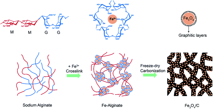
The Fe3O4/C hybrid was synthesized by a simple carbonization of crosslinked Fe-alginate assemblies, as shown in Fig. 1. Typically, 1.5 wt% of sodium alginate aqueous solution were added into 1.5 wt% of ferric trichloride solution, under a volume ratio of 1![[thin space (1/6-em)]](https://www.rsc.org/images/entities/char_2009.gif) :
:![[thin space (1/6-em)]](https://www.rsc.org/images/entities/char_2009.gif) 5. The as-prepared Fe-alginate was freeze-dried for 24 h to remove water. Then the dried Fe-alginate was carbonized at 600 °C for 1 h with N2 atmosphere to obtain the final Fe3O4/C hybrid.
5. The as-prepared Fe-alginate was freeze-dried for 24 h to remove water. Then the dried Fe-alginate was carbonized at 600 °C for 1 h with N2 atmosphere to obtain the final Fe3O4/C hybrid.
2.2. Material characterization
Scanning electron microscope (SEM) observations were carried out on a FEI field emission microscope. Transmission electron microscope (TEM), high-resolution TEM (HR-TEM) and selected area electron diffraction (SAED) studies were performed on a JEOL JEM-2100F. X-ray diffraction (XRD) was conducted on a Rigaku D/Max-2500 with Cu-Kα radiation. Thermogravimetric analysis (TGA) was studied on a Netzsch TGA instrument from 30 to 800 °C with a heating rate of 10 °C min−1 under air. Nitrogen sorption isotherms were measured on a Micromeritics ASAP 2020 at 77 K. Pore size distributions were calculated on the basis of the density function theory (DFT) model. Raman spectra were obtained on a Renishaw in Via-reflex spectrometer with a crystal laser excitation of 532 nm.2.3. Electrochemical measurement
Electrochemical measurements were carried out in half-cell configurations with lithium and sodium foils as counter electrode. To prepare the working electrodes, active materials, Super P, and poly-(vinyl difluoride) (PVDF) with a weight ratio of 8![[thin space (1/6-em)]](https://www.rsc.org/images/entities/char_2009.gif) :
:![[thin space (1/6-em)]](https://www.rsc.org/images/entities/char_2009.gif) 1
1![[thin space (1/6-em)]](https://www.rsc.org/images/entities/char_2009.gif) :
:![[thin space (1/6-em)]](https://www.rsc.org/images/entities/char_2009.gif) 1 were mixed uniformly in the solution of N-methyl-pyrrolidone (NMP) to make a slurry. Then the slurry was coated on a copper foil with a thickness of 100 μm. After drying at 110 °C overnight under vacuum, these coated copper foils were cut into disks, pressed at 4 MPa, and dried for another 12 h at 110 °C in vacuum. Then the as-prepared electrodes were transferred into the glove box filled with argon atmosphere for half-cell assembling. For lithium-half cells, lithium foil was used as the counter electrode, Celgard 2500 was used as the separator, and the electrolyte was a 1 M LiPF6 in ethylene carbonate (EC) and dimethyl carbonate (DMC) (v/v = 1
1 were mixed uniformly in the solution of N-methyl-pyrrolidone (NMP) to make a slurry. Then the slurry was coated on a copper foil with a thickness of 100 μm. After drying at 110 °C overnight under vacuum, these coated copper foils were cut into disks, pressed at 4 MPa, and dried for another 12 h at 110 °C in vacuum. Then the as-prepared electrodes were transferred into the glove box filled with argon atmosphere for half-cell assembling. For lithium-half cells, lithium foil was used as the counter electrode, Celgard 2500 was used as the separator, and the electrolyte was a 1 M LiPF6 in ethylene carbonate (EC) and dimethyl carbonate (DMC) (v/v = 1![[thin space (1/6-em)]](https://www.rsc.org/images/entities/char_2009.gif) :
:![[thin space (1/6-em)]](https://www.rsc.org/images/entities/char_2009.gif) 1). For sodium-half cells, sodium foil was used as the counter electrode, glass fibers (GF/D) from Whatman were used as the separator, and the electrolyte was a 1 M NaClO4 solution in ethylene carbonate (EC) and propylene carbonate (PC) (v/v = 1
1). For sodium-half cells, sodium foil was used as the counter electrode, glass fibers (GF/D) from Whatman were used as the separator, and the electrolyte was a 1 M NaClO4 solution in ethylene carbonate (EC) and propylene carbonate (PC) (v/v = 1![[thin space (1/6-em)]](https://www.rsc.org/images/entities/char_2009.gif) :
:![[thin space (1/6-em)]](https://www.rsc.org/images/entities/char_2009.gif) 1).
1).
The Galvanostatic charge–discharge (GCD) curves were measured on a Land CT2001A at a voltage window of 0.005–3.0 V. The cyclic voltammetry (CV) with a scan rate of 0.1 mV s−1 (0.005–3.0 V) and electrochemical impedance spectroscopy (EIS) with a frequency range of 10 mHz to 100 kHz and ac amplitude of 10 mV were performed on a VMP3 electrochemical working station.
3. Results and discussion
3.1. Microstructures of the Fe3O4/C hybrid
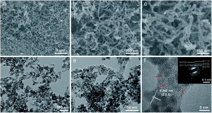
The morphology and microstructure of the as-prepared Fe3O4/C hybrid were characterized by SEM and TEM measurements, as shown in Fig. 2. The hybrid exhibits a nanoscale branch-like foam structure as a whole, with a lot of pores in it (Fig. 2a). On a larger magnification, these thready branches are not separated but integrated with joints, so as to form an integrated network (Fig. 2b and c), which is crucial to keep the physical stability of electrodes during charge–discharge processes. Fig. 2c shows that the surface of these branches are stacked with dense and uniform nanosized particles. The TEM observations in Fig. 2d and e show that the whole branch-like foam is densely composed of uniform Fe3O4 nanoparticles and carbon branches. The HR-TEM image in Fig. 2f shows that these Fe3O4 nanoparticles are around 5 nm in diameter, and are wrapped by 2–3 layers of graphitic carbons. These graphitic layers are produced by the catalytic graphitization of Fe particles. During carbonization, the amorphous carbon structures adjacent to Fe particles are transformed into ordered graphitic layers through dissolution-precipitation mechanism.47 These graphitic layers can buffer the volume change induced stress and facilitate the transfer of electrons to improve the reactive kinetics. This uniform Fe3O4/C hybrid structure is produced by self-crosslinking and hardly achieved by normally solution methods.Fig. 3 shows the chemical component and pore characterization of the Fe3O4/C hybrid. The XRD pattern in Fig. 3a shows several peaks at 18.3, 30.1, 35.4, 37.1, 43.1, 56.9, 62.5 and 73.9°, all of which are indexed to the spinel Fe3O4 (JCPDS: 19-0629). The broad and short XRD peaks indicate that the Fe3O4 particles are nano sized, as verified by TEM images. The TGA curve in Fig. 3b shows sharp weight decrease at 300–500 °C, which is ascribed to the combustion of carbons of the Fe3O4/C hybrid (C + O2 → CO2) in air. The remaining weight after 500 °C is provided by Fe3O4 nanoparticles and the weight percentage of Fe3O4 nanoparticles is thus calculated to be 58.8%. The N2 adsorption–desorption isotherm in Fig. 3c shows a typical type-IV curve with distinct increase of N2 adsorption and hysteresis loop at the moderate and high relative pressure. The Fe3O4/C hybrid shows a relatively high specific surface area of 389.8 m2 g−1. The pore size distribution inset in Fig. 3c shows the existence of large number of mesopores and macropores. The mesopores were induced by Fe3+ crosslinking, where Fe3+ ions crosslinked with adjacent G blocks in alginate, leaving space among the M blocks. The rearrangement of G/M blocks results in the mesoporous channels around the crosslinked nanostructures. Macropores were mostly produced by the freeze-drying process,48 as sublimation of ice would leave lot of spaces. This interconnected hierarchical porous structure can facilitate the mass transport and buffer the volume change during the charging/discharging processes when applied as electrodes of LIBs and NIBs.49–53 Particularly, the mesopores are preferred in NIBs, since the radius of Na+ (0.102 nm) is larger than that of Li+ (0.076 nm).54,55 Raman spectrum in Fig. 3d shows characteristic peaks for both the Fe3O4 nanoparticles and the carbon framework. The four weak peaks at 219, 282, 384 and 656 cm−1 are ascribed to the Raman active models of Fe3O4. The two sharp peaks at 1359 and 1585 cm−1 are attributed to the D- and G-band of carbons, respectively. The D-band corresponds to the response from defects and disordered carbons, while the G-band represents the C–C stretching mode of the highly ordered graphitic layers with a sp2 orbital structure. The IG/ID value of Fe3O4/C hybrid is as high as 1.26, indicating a high degree of graphitization. Such high degree of graphitization at low carbonization temperature of 600 °C is related to the catalytic graphitization of Fe nanoparticles.56,57
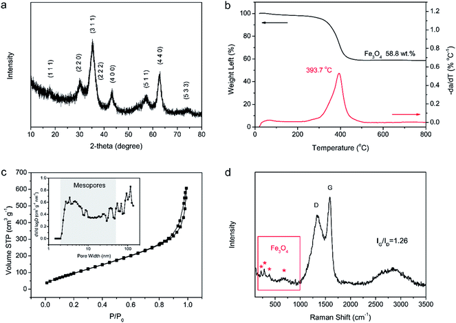 | ||
| Fig. 3 Chemical component and pore characterization of Fe3O4/C hybrid. (a) XRD pattern. (b) TGA curves. (c) N2 isothermal and pore size distribution. (d) Raman spectrum. | ||
3.2. Electrochemical performance of the LIBs
The electrochemical performance of Fe3O4/C hybrid was firstly tested in the lithium half-cells. Fig. 4a shows the first three CV curves with scan rate of 0.1 mV s−1 at voltage window of 0.005–3 V. In the first discharge, the little peak at 0.96 V and the sharp peak at 0.68 V are related to the formation of solid electrolyte interphase (SEI) film, corresponding to the two-step lithiation reaction of Fe3O4 (step 1, Fe3O4 + 2Li+ + 2e− → Li2(Fe3O4); and step 2, Li2(Fe3O4) + 6Li+ + 6e− → 4Li2O + 3Fe).35,36 In the following cycles, the only reduction peak at 0.76 V is attributed to the reduction from Fe3O4 to Fe. The two peaks at 1.56 and 1.88 V in the charge process are ascribed to the oxidization from Fe to Fe3O4. Besides, the sharp reduction peak near 0.1 V and the broad oxidation peak near 0.2 V are ascribed to the insertion/extraction of Li into/from graphitic layers in the carbon matrix.58 Fig. 4b shows the first three GCD profiles at 0.1 A g−1 within voltage range of 0.005–3 V. The GCD profiles match well with the CV curves above. In the first discharge, the short plateau at 1.05 V and the longer plateau at 0.80 V correspond to the two discharge peaks at the first discharge CV curve, indicating the formation of SEI film and the two-step reduction from Fe3O4 to Fe. In the subsequent cycles, the plateau at 0.92 V in the discharge process and the big slop at 1.5–2.0 V in the charge process correspond to the electrochemical reduction/oxidization (Fe3O4 ↔ Fe), matching well with the peaks in CV curves. The Fe3O4/C hybrid delivers a high lithium storage capacity of 1630 mA h g−1 in the first discharge, based on the total mass of the Fe3O4/C hybrid. The first charge capacity is calculated to be 901 mA h g−1, yielding a low initial coulombic efficiency of 55.3%. The capacity loss in the first cycle is attributed to the irreversible consumption of electrolyte and formation of SEI film on the porous surface of Fe3O4/C hybrid. In practical application, the low initial coulombic efficiency-caused lithium consumption can be solved by a pre-lithiation treatment of electrodes.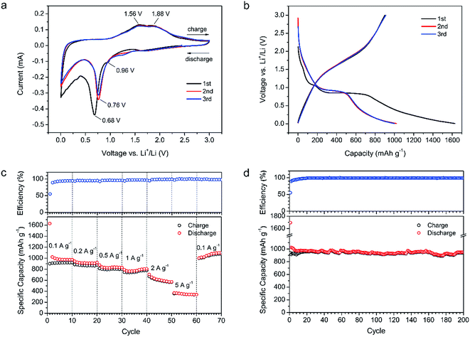 | ||
| Fig. 4 Electrochemical performance of the Fe3O4/C hybrid in LIBs. (a) CV curves. (b) GCD profiles. (c) Rate performance. (d) Cycling performance at 0.1 A g−1. | ||
Fig. 4c shows the rate performance and corresponding coulombic efficiency of the Fe3O4/C based LIBs at various current densities ranging from 0.1 to 5 A g−1. During the first ten cycles at 0.1 A g−1, the discharge capacity decays from 1630 mA h g−1 in the first cycle, to 1022 mA h g−1 in the second cycle, and then gradually to 974 mA h g−1 in the tenth cycle. This gradual capacity decay corresponds to the continuous yet gradually ceasing SEI growth on the surfaces of the Fe3O4 and carbon matrix.59 The discharge capacities of Fe3O4/C hybrid at 0.1, 0.2, 0.5, 1, 2 and 5 A g−1, are calculated to be 973, 920, 832, 805, 570 and 339 mA h g−1, in the 10th, 20th, 30th, 40th, 50th and 60th cycles, respectively. As the current density returned to the initial value of 0.1 A g−1 in the 61st cycle, a capacity of 1002 mA h g−1 is still recoverable and sustainable up to the 70th cycle without any loss (1097 mA h g−1 at the 70th cycle). These values are higher than most reported Fe3O4-based materials, like 3D Fe3O4@GS/GF,34 GF@Fe3O4,35 Fe3O4@mC,42 G-Fe3O4-GNRs,43 and G-Fe3O4@C,60 as summarized in Table S1.† The high specific capacity and excellent rate performance of our Fe3O4/C are ascribed to the nano size of active Fe3O4 (∼5 nm), rational mesoporous channels and abundant graphitic electron pathways in the carbon matrix. First, the nanosized Fe3O4 can provide high reactive surface area for the Li+/Li reactions. Second, the short surface-to-core distance of nanosized Fe3O4 can facilitate the diffusion of Li+. Third, the sufficient and rational mesopore channels can provide efficient transportation paths for electrolyte ions even at high current densities. Fourth, the abundant graphitic carbons can facilitate the transportation of electrons. Thus, high capacities and excellent rate performance are obtained.
Fig. 4d shows the cycling performance of the Fe3O4/C-based LIBs at 0.1 A g−1. After a slight decrease in the first ten cycles, the Fe3O4/C hybrid shows stable cyclic performance with a capacity retention of 952 mA h g−1 in the 200th cycle, which is 98% of the 10th capacity (972 mA h g−1). The high specific capacity over the theoretical value of Fe3O4 (926 mA h g−1) and carbon (372 mA h g−1 for graphite and 744 mA h g−1 for graphene) in the hybrid are mainly attributed to three factors. First, the large surface area of the hierarchical porous carbon matrix and nanosized Fe3O4 can attribute to the lithium storage through surface adsorption.58,61 Second, the functional groups on the surface of the hybrid can provide additional faradic capacity. Third, the reversible decomposition of the electrolyte with the formation of SEI and extra lithium ion adsorption/desorption on the SEI during cycling may also offer lithium storage capacity.58 During cycling, the corresponding coulombic efficiency quickly increases from the initial 55–98% in the 15th cycles, and then maintains high values ca. 99% in the following cycles, revealing the high reversible conversion reactions between the nanosized Fe3O4 and Li+. The high reversibility and excellent cycling stability is attributed to the robust and integrated microstructure of Fe3O4/C hybrid. Generally, Fe3O4 particles suffers from large volume expansion during charge–discharge cycling accompanying by large strain and stress, leading to the pulverization of electrodes and the decrease in capacity during cycling. In our Fe3O4/C hybrid, the Fe3O4 nanoparticles are firstly wrapped by few layers of graphitic carbons and then well-embedded in the robust and interconnected carbon branches. The volume change-induced strain and stress can be well buffered by the dual protection of carbons, thus avoiding the pulverization of electrode and leading to an excellent cyclic performance. The microstructure comparison of the Fe3O4/C before and after cycling are shown in Fig. 5. After 200 cycles at 0.1 A g−1, the size of Fe3O4 nanoparticles expands from the initial 5 nm to 8–10 nm (Fig. 5c and f), while the morphology of Fe3O4 tends to change from solid to hollow (Fig. 5b and e). Despite of the distinct volume expansion, the expanded Fe3O4 nanoparticles are still uniformly embedded in the carbon matrix (Fig. 5d), demonstrating the robust microstructure of our Fe3O4/C hybrid. In a full LIB, to match with the cathode, the high capacity of the Fe3O4/C (974 mA h g−1 vs. 372 mA h g−1 for commercial graphite anode) may contribute to less weight of anode, but the high delithiation potential (∼1.5 V vs. ∼0.1 V for graphite) would lead to the reduction of discharge voltage, which is a common disadvantage for metal oxides/sulfides-based anodes. In the future, with the development of high-voltage cathode materials (e.g., 5 V or above), the disadvantage of high delithiation potential would be suppressed and the advantage of high specific capacity would win out and lead to higher energy density.
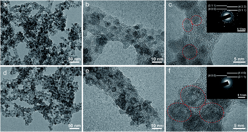 | ||
| Fig. 5 Microstructural comparison of the Fe3O4/C hybrid before and after 200 cycles at 0.1 A g−1 in LIBs. (a–c) TEMs before cycling. (d–f) TEMs after cycling. | ||
3.3. Electrochemical performance of the NIBs
Since the conversion reaction between Fe3O4 and Li+ is similar to that between Fe3O4 and Na+, and the mesoporous channels of the Fe3O4/C hybrid are big enough for Na+ insertion/extraction, the electrochemical performance of the Fe3O4/C hybrid was also measured as the anode of NIBs. The corresponding electrochemical performance in NIBs is shown in Fig. 6. Fig. 6a shows the first three CV curves at a scan rate of 0.1 mV s−1 within the voltage window of 0.005–3 V. Compared with the CV peaks for LIBs, the CV peaks for NIBs are much weaker and broader due to the sluggish diffusion of sodium ions.40 The broad peaks at 1.15 and 0.55 V in the first discharge are attributed to the formation of SEI film, as well as the two-step transition from Fe3O4 to Fe (step 1, Fe3O4 + 2Na+ + 2e− → Na2(Fe3O4); and step 2, Na2(Fe3O4) + 6Na+ + 6e− → 4Na2O + 3Fe). In the following cycles, the reduction peaks at 0.70 V correspond to the conversion from Fe3O4 to Fe. The oxidization peaks at 0.75 and 1.30 V are related to the transition from Fe to Fe3O4. There are also sharp reduction peaks near 0.1 V and broad oxidation peaks near 0.2 V, corresponding to the Na insertion/extraction in graphitic layers. Fig. 6b shows the GCD profiles of the first three cycles at 0.05 A g−1 in the voltage window of 0.005–3 V. The voltages increase and decrease smoothly without apparent plateaus, which is in accordance with the weak and broad CV peaks. The Fe3O4/C hybrid exhibits an initial discharge capacity of 1161 mA h g−1 and charge capacity of 321 mA h g−1, with coulombic efficiency of 27.6%. Such low initial coulombic efficiency is mainly attributed to the SEI film formation on the large surface area of Fe3O4/C hybrid and the electrolyte decomposition.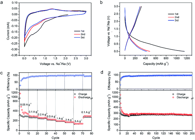 | ||
| Fig. 6 Electrochemical performance of the Fe3O4/C hybrid in NIBs. (a) CV curves. (b) GCD profiles. (c) Rate performance. (d) Cycling performance at 0.1 A g−1. | ||
Fig. 6c shows the rate performance and corresponding coulombic efficiency at various current densities from 0.05 to 5 A g−1. During the first ten cycles at 0.05 A g−1, the discharge capacity decays from 1161 mA h g−1 in the first cycle, to 487 mA h g−1 in the second cycle, and then gradually to the 339 mA h g−1 in the tenth cycle, which is caused by the gradual formation of SEI film. The discharge capacities of the Fe3O4/C electrode at the current density of 0.05, 0.1, 0.2, 0.5, 1, 2 and 5 A g−1 are calculated to be 339, 293, 262, 223, 195, 169 and 138 mA h g−1, respectively, in the 10th, 20th, 30th, 40th, 50th, 60th and 70th cycles. When the current density returns to 0.1 A g−1, a reversible capacity of 295 mA h g−1 is recovered, showing a good rate performance. Similar to the situation in LIBs, such good rate performance and relatively high specific capacity are attributed to the nano-sized Fe3O4, rational mesoporous channels and abundant graphitic electron pathways in the carbon matrix.
Fig. 6d shows the cycling performance of the Fe3O4/C hybrid in NIBs at current density of 0.1 A g−1. The fast capacity loss in the first ten cycles is ascribed to the gradual formation of SEI film, as we have discussed above. In the latter 190 cycles, the capacity remains stable with little decay. The discharge capacity at the 200th cycle is 277 mA h g−1, which is 93.5% of the 10th discharge capacity (296 mA h g−1), indicating an excellent cycling stability. As we have discussed in LIBs, such good cycling stability in NIBs is also attributed to the robust and integrated microstructure of Fe3O4/C. The microstructure of Fe3O4/C hybrid after 200 cycles in NIBs were also measured by the TEM, as shown in Fig. 7. Unlike in LIBs, the Fe3O4 nanoparticles don't have apparent volume expansion after cycling in NIBs, indicating the less intense reaction between Fe3O4 and sodium. After 200 cycles, the nanosized Fe3O4 are still uniformly embedded in the branch-like carbon frameworks, demonstrating the physical stability of the hybrid structure.
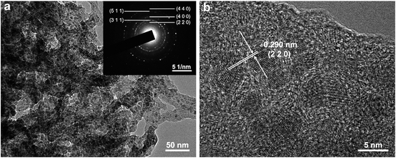 | ||
| Fig. 7 Microstructure of the Fe3O4/C hybrid after 200 cycles at 0.1 A g−1 in NIBs. (a) TEM and SAED (inset). (b) HR-TEM. | ||
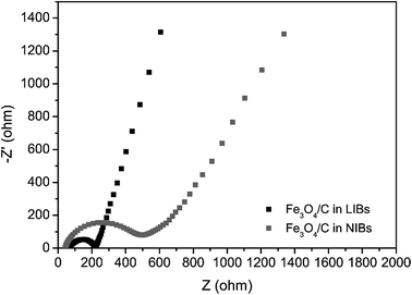
The rate performance and cyclic capability of our Fe3O4/C-based NIBs are better than most other Fe3O4-based materials, like RGO/Fe3O4,62 C/Fe3O4 embedded on CNTs,63 Fe3O4 nanoparticles,64 and Fe3O4/graphene,65 as summarized in Table S2.† However, the specific capacities of the Fe3O4/C in NIBs are much lower than the corresponding values in LIBs. This is a usual phenomenon for most dual-role anode materials.40,66–70 The phenomenon is mainly caused by the poor kinetics of the sodiation/desodiation processes.40 To verify this, EIS of the Fe3O4/C-based LIBs and NIBs were measured with a frequency range of 10 mHz to 100 kHz and ac amplitude of 10 mV after three CV cycles. Fig. 8 shows the Nyquist plots of the Fe3O4/C electrode in LIBs and NIBs. The spectra are fitted based on the equivalent circuit in Fig. S1† and the detailed kinetic parameters are listed in Table S3.† In the high frequency region, the intersection of the plot at real part Z′ corresponds to the electrical connection resistance of cells (Rs). In the medium frequency region, the diameter of the semicircle indicates the charge-transfer resistance at the electrode/electrolyte interface (Rct). It is obvious that the charge-transfer resistance in NIBs are much larger than that in LIBs (the fitted Rct for NIBs and LIBs are 445.8 Ω and 162.6 Ω, respectively). This indicates that the Na+ insertion from the electrolyte to electrode is much slower than Li+ insertion. In the low frequency region, the slope of the curves corresponds to the diffusive resistance of electrolyte ions inside electrode materials (Zw, Warburg impedance). The slope of Fe3O4/C in LIBs is higher than in NIBs, indicating that Li+ suffers lower impedance during diffusion and reactions inside electrodes compared to Na+. Thus, the EIS proves that Na+ insertion/extraction in Fe3O4/C-based electrode bears larger impedance and poorer kinetics compared with Li+, resulting in a lower capacity in NIBs at the same scan rate than in LIBs.
4. Conclusions
In summary, we have demonstrated the effective role of a 3D integrated branch-like Fe3O4/C nanostructure in alleviating the volume change and stress problems of Fe3O4 during Li+/Na+ insertion/extraction. The unique nanostructure is synthesized through a simple carbonization of self-crosslinked Fe-alginate. The obtained Fe3O4/C nanohybrid owns ultrafine Fe3O4 particle size, mesoporous channels, partially graphitized carbons, and especially a unique integrated branch-like nanostructure. When applied in the anodes of LIBs and NIBs, the ultrafine Fe3O4 particle size can help generate high specific capacities, the mesoporous channels and appropriate degree of graphitization can help improve the rate performance, and the robust 3D integrated branch-like structure can well buffer the volume expansions and stresses to keep a physically structural stability and lead to an excellent cyclic stability. With regard to the facile synthesis, excellent electrochemical performance and renewable raw materials, the Fe3O4/C hybrids are of great promise for the practical anode materials of LIBs and NIBs.Conflicts of interest
There are no conflicts to declare.Acknowledgements
This work was supported by National Key R&D Program of China (2017YFB1201005), National Natural Science Foundation of China (No. 51772187, 51572169), Shanghai Science and Technology Committee (17ZR1441400, 15ZR1422400, 16520710900), and Baotou-SJTU Materials Research Institute. We also thank SJTU Instrument Analysis Centre for the measurements.References
- J. B. Goodenough and K.-S. Park, J. Am. Chem. Soc., 2013, 135, 1167–1176 CrossRef CAS PubMed.
- V. Etacheri, R. Marom, R. Elazari, G. Salitra and D. Aurbach, Energy Environ. Sci., 2011, 4, 3243–3262 CAS.
- B. Kang and G. Ceder, Nature, 2009, 458, 190–193 CrossRef CAS PubMed.
- C. Zhang, W. Lv, Y. Tao and Q. H. Yang, Energy Environ. Sci., 2015, 8, 1390–1403 CAS.
- H. Y. Kang, Y. C. Liu, K. Z. Cao, Y. Zhao, L. F. Jiao, Y. J. Wang and H. T. Yuan, J. Mater. Chem. A, 2015, 3, 17899–17913 CAS.
- Y. C. Liu, N. Zhang, L. F. Jiao and J. Chen, Adv. Mater., 2015, 27, 6702–6707 CrossRef CAS PubMed.
- J. C. Wang and S. Kaskel, J. Mater. Chem., 2012, 22, 23710–23725 RSC.
- L. H. Yu, N. Brun, K. Sakaushi, J. Eckert and M. M. Titirici, Carbon, 2013, 61, 245–253 CrossRef CAS.
- N. Brun, K. Sakaushi, J. Eckert and M. M. Titirici, ACS Sustainable Chem. Eng., 2014, 2, 126–129 CrossRef CAS.
- W. Nickel, M. Oschatz, S. Rico-Frances, S. Klosz, T. Biemelt, G. Mondin, A. Eychmuller, J. Silvestre-Albero and S. Kaskel, Chem.–Eur. J., 2015, 21, 14753–14757 CrossRef CAS PubMed.
- L. L. Kong, Z. Zhang, Y. Z. Zhang, S. Liu, G. R. Li and X. P. Gao, ACS Appl. Mater. Interfaces, 2016, 8, 31684–31694 CAS.
- L. P. Ding, S. L. He, S. D. Miao, M. R. Jorgensen, S. Leubner, C. L. Yan, S. G. Hickey, A. Eychmuller, J. Z. Xu and O. G. Schmidt, Sci. Rep., 2014, 4, 4647 CrossRef PubMed.
- M. H. Wang, H. Yang, X. L. Zhou, W. Shi, Z. Zhou and P. Cheng, Chem. Commun., 2016, 52, 717–720 RSC.
- D. H. Yang, X. L. Zhou, M. Zhong, Z. Zhou and X. H. Bu, ChemNanoMat, 2017, 3, 252–258 CrossRef CAS.
- F. Cheng, Z. Tao, J. Liang and J. Chen, Chem. Mater., 2008, 20, 667–681 CrossRef CAS.
- X. P. Han, F. Y. Cheng, C. C. Chen, Y. X. Hu and J. Chen, Nano Res., 2015, 8, 156–164 CrossRef CAS.
- Y. X. Hu, T. R. Zhang, F. Y. Cheng, Q. Zhao, X. P. Han and J. Chen, Angew. Chem., Int. Ed., 2015, 54, 4338–4343 CrossRef CAS PubMed.
- S. Li, C. Cheng, H. W. Liang, X. L. Feng and A. Thomas, Adv. Mater., 2017, 29, 1700707 CrossRef PubMed.
- T. Szatkowski, M. Wysokowski, G. Lota, D. Peziak, V. V. Bazhenov, G. Nowaczyk, J. Walter, S. L. Molodtsov, H. Stocker, C. Himcinschi, L. Petrenko, A. L. Stelling, S. Jurga, T. Jesionowskia and H. Ehrlich, RSC Adv., 2015, 5, 79031–79040 RSC.
- J. N. Zhang, K. X. Wang, Q. Xu, Y. C. Zhou, F. Y. Cheng and S. J. Guo, ACS Nano, 2015, 9, 3369–3376 CrossRef CAS PubMed.
- D. Tian, X. L. Zhou, Y. H. Zhang, Z. Zhou and X. H. Bu, Inorg. Chem., 2015, 54, 8159–8161 CrossRef CAS PubMed.
- X. L. Sun, G. P. Hao, X. Y. Lu, L. X. Xi, B. Liu, W. P. Si, C. S. Ma, Q. M. Liu, Q. Zhang, S. Kaskel and O. G. Schmidt, J. Mater. Chem. A, 2016, 4, 10166–10173 CAS.
- T. Jaumann, J. Balach, M. Klose, S. Oswald, J. Eckert and L. Giebeler, J. Electrochem. Soc., 2016, 163, A557–A564 CrossRef CAS.
- M. Adam, P. Strubel, L. Borchardt, H. Althues, S. Dorfler and S. Kasker, J. Mater. Chem. A, 2015, 3, 24103–24111 CAS.
- R. G. Mendes, A. Bachmatiuk, B. Buchner, G. Cuniberti and M. H. Rummeli, J. Mater. Chem. B, 2013, 1, 401–428 RSC.
- G. H. Li, H. Yang, F. C. Li, J. Du, W. Shi and P. Cheng, J. Mater. Chem. A, 2016, 4, 9593–9599 CAS.
- M. Zhong, D. H. Yang, C. C. Xie, Z. Zhang, Z. Zhou and X. H. Bu, Small, 2016, 12, 5564–5571 CrossRef CAS PubMed.
- Y. T. Zuo, G. Wang, J. Peng, G. Li, Y. Q. Ma, F. Yu, B. Dai, X. H. Guo and C. P. Wong, J. Mater. Chem. A, 2016, 4, 2453–2460 CAS.
- Y. Yang, J. Q. Li, D. Q. Chen and J. B. Zhao, ACS Appl. Mater. Interfaces, 2016, 8, 26730–26739 CAS.
- Y. Wang, Q. T. Qu, Y. Y. Han, T. Gao, J. Shao, Z. C. Zuo, W. J. Liu, Q. Shi and H. H. Zheng, J. Mater. Chem. A, 2016, 4, 10314–10320 CAS.
- J. Liu, X. J. Xu, R. Z. Hu, L. C. Yang and M. Zhu, Adv. Energy Mater., 2016, 6, 1600256 CrossRef.
- J. Q. Jiao, W. D. Qiu, J. G. Tang, L. P. Chen and L. Y. Jing, Nano Res., 2016, 9, 1256–1266 CrossRef CAS.
- C. Ding, Y. W. Zeng, L. L. Cao, L. F. Zhao and Y. Zhang, J. Mater. Chem. A, 2016, 4, 5898–5908 CAS.
- W. Wei, S. B. Yang, H. X. Zhou, I. Lieberwirth, X. L. Feng and K. Mullen, Adv. Mater., 2013, 25, 2909–2914 CrossRef CAS PubMed.
- J. S. Luo, J. L. Liu, Z. Y. Zeng, C. F. Ng, L. J. Ma, H. Zhang, J. Y. Lin, Z. X. Shen and H. J. Fan, Nano Lett., 2013, 13, 6136–6143 CrossRef CAS PubMed.
- C. N. He, S. Wu, N. Q. Zhao, C. S. Shi, E. Z. Liu and J. J. Li, ACS Nano, 2013, 7, 4459–4469 CrossRef CAS PubMed.
- S. K. Behera, Chem. Commun., 2011, 47, 10371–10373 RSC.
- S. Zhu, A. C. Marschilok, E. S. Takeuchi, G. T. Yee, G. Wang and K. J. Takeuchi, J. Electrochem. Soc., 2010, 157, A1158–A1163 CrossRef CAS.
- L. Liu, H. Zhang, S. W. Liu, H. M. Yao, H. Q. Hou and S. L. Chen, Electrochim. Acta, 2016, 219, 356–362 CrossRef CAS.
- S. Liu, Y. Wang, Y. Dong, Z. Zhao, Z. Wang and J. Qiu, ChemElectroChem, 2016, 3, 38–44 CrossRef CAS.
- J. Z. Wang, C. Zhong, D. Wexler, N. H. Idris, Z. X. Wang, L. Q. Chen and H. K. Liu, Chem.–Eur. J., 2011, 17, 661–667 CrossRef CAS PubMed.
- Y. Chen, B. H. Song, M. Li, L. Lu and J. M. Xue, Adv. Funct. Mater., 2014, 24, 319–326 CrossRef CAS.
- L. Li, A. Kovalchuk, H. L. Fei, Z. W. Peng, Y. L. Li, N. D. Kim, C. S. Xiang, Y. Yang, G. D. Ruan and J. M. Tour, Adv. Energy Mater., 2015, 5, 1500171 CrossRef.
- S. N. Pawar and K. J. Edgar, Biomaterials, 2012, 33, 3279–3305 CrossRef CAS PubMed.
- K. Y. Lee and D. J. Mooney, Prog. Polym. Sci., 2012, 37, 106–126 CrossRef CAS PubMed.
- N. Wang, Q. L. Liu, D. M. Kang, J. J. Gu, W. Zhang and D. Zhang, ACS Appl. Mater. Interfaces, 2016, 8, 16035–16044 CAS.
- A. Ōya and S. Ōtani, Carbon, 1979, 17, 131–137 CrossRef.
- Y. Li, Q. Liu, D. Kang, J. Gu, W. Zhang and D. Zhang, J. Mater. Chem. A, 2015, 21016–21022 CAS.
- B. Fang, M. S. Kim, J. H. Kim, S. Lim and J. S. Yu, J. Mater. Chem., 2010, 20, 10253–10259 RSC.
- M. S. Kim, B. Z. Fang, J. H. Kim, D. Yang, Y. K. Kim, T. S. Bae and J. S. Yu, J. Mater. Chem., 2011, 21, 19362–19367 RSC.
- B. Fang, J. H. Kim, M. S. Kim and J. S. Yu, Acc. Chem. Res., 2013, 46, 1397–1406 CrossRef CAS PubMed.
- Y. L. Xing, Y. J. Wang, C. G. Zhou, S. C. Zhang and B. Z. Fang, ACS Appl. Mater. Interfaces, 2014, 6, 2561–2567 CAS.
- A. Eftekhari and B. Fang, Int. J. Hydrogen Energy, 2017, 25143–25165 CrossRef CAS.
- M.-S. Balogun, Y. Luo, W. Qiu, P. Liu and Y. Tong, Carbon, 2016, 98, 162–178 CrossRef CAS.
- N. Zhang, X. P. Han, Y. C. Liu, X. F. Hu, Q. Zhao and J. Chen, Adv. Energy Mater., 2015, 5, 1401123 CrossRef.
- M. Sevilla, C. S. Martínez-de Lecea, T. Valdés-Solís, E. Morallón and A. B. Fuertes, Phys. Chem. Chem. Phys., 2008, 10, 1433–1442 RSC.
- F. Maldonado-Hodar, C. Moreno-Castilla, J. Rivera-Utrilla, Y. Hanzawa and Y. Yamada, Langmuir, 2000, 16, 4367–4373 CrossRef CAS.
- C. X. Peng, B. D. Chen, Y. Qin, S. H. Yang, C. Z. Li, Y. H. Zuo, S. Y. Liu and J. H. Yang, ACS Nano, 2012, 6, 1074–1081 CrossRef CAS PubMed.
- Z.-L. Yu, S. Xin, Y. You, L. Yu, Y. Lin, D.-W. Xu, C. Qiao, Z.-H. Huang, N. Yang, S.-H. Yu and J. B. Goodenough, J. Am. Chem. Soc., 2016, 138, 14915–14922 CrossRef CAS PubMed.
- L. Zhao, M. M. Gao, W. B. Yue, Y. Jiang, Y. Wang, Y. Ren and F. Q. Hu, ACS Appl. Mater. Interfaces, 2015, 7, 9709–9715 CAS.
- Z. S. Wu, W. C. Ren, L. Wen, L. B. Gao, J. P. Zhao, Z. P. Chen, G. M. Zhou, F. Li and H. M. Cheng, ACS Nano, 2010, 4, 3187–3194 CrossRef CAS PubMed.
- S. Zhang, W. Li, B. Tan, S. Chou, Z. Li and S. Dou, J. Mater. Chem. A, 2015, 3, 4793–4798 CAS.
- D.-Y. Park and S.-T. Myung, ACS Appl. Mater. Interfaces, 2014, 6, 11749–11757 CAS.
- P. R. Kumar, Y. H. Jung, K. K. Bharathi, C. H. Lim and D. K. Kim, Electrochim. Acta, 2014, 146, 503–510 CrossRef CAS.
- Y. Fu, Q. Wei, X. Wang, G. Zhang, H. Shu, X. Yang, A. C. Tavares and S. Sun, RSC Adv., 2016, 6, 16624–16633 RSC.
- F. Fu, J. D. Li, Y. Z. Yao, X. P. Qin, Y. B. Dou, H. Y. Wang, J. K. Tsui, K. Y. Chan and M. H. Shao, ACS Appl. Mater. Interfaces, 2017, 9, 16194–16201 CAS.
- Z. H. Bi, M. P. Paranthaman, P. A. Menchhofer, R. R. Dehoff, C. A. Bridges, M. F. Chi, B. K. Guo, X. G. Sun and S. Dai, J. Power Sources, 2013, 222, 461–466 CrossRef CAS.
- X. J. Li, A. L. Hector, J. R. Owen and S. I. U. Shah, J. Mater. Chem. A, 2016, 4, 5081–5087 CAS.
- A. Y. Kim, M. K. Kim, K. Cho, J. Y. Woo, Y. Lee, S. H. Han, D. Byun, W. Choi and J. K. Lee, ACS Appl. Mater. Interfaces, 2016, 8, 19514–19523 CAS.
- S. Hariharan, K. Saravanan, V. Ramar and P. Balaya, Phys. Chem. Chem. Phys., 2013, 15, 2945–2953 RSC.
Footnote |
| † Electronic supplementary information (ESI) available. See DOI: 10.1039/c7ra09348a |
| This journal is © The Royal Society of Chemistry 2017 |

