 Open Access Article
Facile synthesis of NASICON-type Li1.3Al0.3Ti1.7(PO4)3 solid electrolyte and its application for enhanced cyclic performance in lithium ion batteries through the introduction of an artificial Li3PO4 SEI layer†
Jianyu Liuab,
Tao Liuab,
Yujie Puab,
Mingming Guana,
Zhiyuan Tang *ab,
Fei Ding*c,
Zhibin Xuc and
Yang Lic
aSchool of Chemical and Engineering, Tianjin University, Tianjin, 300072, PR China. E-mail: tangzhiyuantju@163.com
bDepartment of Applied Chemistry, School of Chemical Engineering and Technology, Tianjin University, Tianjin 300072, PR China
cNational Key Lab of Power Sources, Tianjin Institute of Power Sources, Tianjin 300384, PR China. E-mail: hilldingfei@163.com
First published on 2nd October 2017
Abstract
The pure Li1.3Al0.3Ti1.7(PO4)3 (LATP) ceramic powders with uniform distribution have been successfully synthesized with CO(NH2)2 as a molten flux at a relatively lower temperature compared to conventional methods. The influences of the molar ratio of molten CO(NH2)2 to reaction precursor, calcination temperature for the LATP powders and the sintering temperature for the LATP pellets are investigated; the pellet with the highest total conductivity of 7.02 × 10⁻⁴ S cm−1 at room temperature is obtained. In addition, in view of the instability between LATP and metallic lithium, we introduce an artificial Li3PO4 SEI (solid electrolyte interphase) layer to block the contacts between them. The results of galvanostatic charge–discharge measurement show that the as-assembled battery delivers an excellent capacity retention ratio of 95.2% at 0.1C rate after 50 cycles, which is much higher than untreated samples. We conclude that adding an artificial Li3PO4 SEI layer is an effective way to improve the electrochemical property of solid state lithium ion batteries (LIBs) with LATP as an electrolyte.
1. Introduction
Since the commercialization of lithium ion batteries, LIBs have been widely used as power sources for portable electronic devices due to their attractive energy density, light weight and long cycle life.1–6 However, conventional LIBs with organic liquid electrolytes suffer from the problem of leakage and flammability, which limits their large-scale applications.7–11 Thus, seeking new electrolyte materials with high safety to replace the traditional electrolyte is necessary.In the past two decades, several types of inorganic solid-state electrolyte materials, such as NASICON-type Li1+xAlxM2−x(PO4)3 (M = Ti, Ge),12 perovskite-type Li3xLa2/3−xTiO3,13 Li2S-based sulfide glasses14,15 and garnet-type Li7La3Zr2O12,16,17 have been extensively synthesized and used as the electrolyte materials for LIBs. Among the above-mentioned solid electrolytes, NASICON-type ceramics, Li1+xAlxTi2−x(PO4)3, have attracted increasing attention because of their comparatively higher lithium ion conductivity at room temperature, air-stability as well as the relatively low cost for synthesis.18–20 Hence, NASICON-type ceramics have been considered as potential candidates for large-scale production. Currently, various synthesis approaches have been attempted to prepare the LATP samples, including melt-quenching, co-precipitation method, sol–gel method, solid-state reaction, hydrothermal synthesis and microwave method. Fu et al.21 prepared Li1+xAlxTi2−x(PO4)3 by melt-quenching method at 1450 °C and the obtained material shows an extremely high conductivity of 1.30 × 10⁻³ S cm−1 at room temperature, which represents the highest level for LATP that can be achieved at present. Kwang et al.22 synthesized Li1+xAlxTi2−x(PO4)3 via hydrothermal reaction and examined the effects of the preparation conditions. The total conductivity of optimal product achieved was 5.50 × 10⁻⁴ S cm−1. However, these techniques often require high temperature or complex production process, which limits the mass production of LATP. Therefore, developing an easier and more convenient method becomes an urgent task for researchers.
In addition, it is well known that LATP is unstable in presence of metallic lithium due to the Ti4+/Ti3+ redox reaction. This problem can be solved by adopting a barrier layer between electrolyte and metallic lithium to block contact between them and prevent unfavorable chemical reactions. However, in a previous study, this buffer layer was prepared by radio-frequency (RF) reactive magnetron sputtering,23 which is not suitable for large scale production because of its complex and expensive preparation process.
In this study, we use CO(NH2)2 as a molten flux to prepare Li1.3Al0.3Ti1.7(PO4)3, which is similar to the molten salt method.24–26 The molten flux as reaction media can provide a liquid environment to speed up the ion transmission and would reduce the synthesis temperature and reaction time. Compared to conventional methods, this route is convenient to achieve the mass production of LATP. Moreover, in order to solve the problem of redox reaction between the LATP solid electrolyte and lithium metal, we introduce an artificial Li3PO4 SEI layer27 to block the contact between them, which will prevent unfavorable chemical reactions. This is the first time such a method is reported. The results of galvanostatic charge–discharge measurement indicate that the cyclic performance has been improved significantly, which was not observed in previous studies.
2. Experimental
2.1 Synthesis and characterization of LATP electrolyte materials
The Li1.3Al0.3Ti1.7(PO4)3 solid electrolyte was synthesized with CO(NH2)2 as a molten flux. Stoichiometric amount of LiNO3, Al2O3, TiO2, NH4H2PO4 (the molar ratio of Li![[thin space (1/6-em)]](https://www.rsc.org/images/entities/char_2009.gif) :
:![[thin space (1/6-em)]](https://www.rsc.org/images/entities/char_2009.gif) Al
Al![[thin space (1/6-em)]](https://www.rsc.org/images/entities/char_2009.gif) :
:![[thin space (1/6-em)]](https://www.rsc.org/images/entities/char_2009.gif) Ti
Ti![[thin space (1/6-em)]](https://www.rsc.org/images/entities/char_2009.gif) :
:![[thin space (1/6-em)]](https://www.rsc.org/images/entities/char_2009.gif) P = 1.3
P = 1.3![[thin space (1/6-em)]](https://www.rsc.org/images/entities/char_2009.gif) :
:![[thin space (1/6-em)]](https://www.rsc.org/images/entities/char_2009.gif) 0.3
0.3![[thin space (1/6-em)]](https://www.rsc.org/images/entities/char_2009.gif) :
:![[thin space (1/6-em)]](https://www.rsc.org/images/entities/char_2009.gif) 1.7
1.7![[thin space (1/6-em)]](https://www.rsc.org/images/entities/char_2009.gif) :
:![[thin space (1/6-em)]](https://www.rsc.org/images/entities/char_2009.gif) 3) were first placed in an alumina crucible. Subsequently, different contents of CO(NH2)2 (D) were added into the above reactants in which D was defined as the molar ratio of NH4H2PO4/CO(NH2)2, and D varies between 1/0 and 1/3. Then, stirring was continued until they were mixed homogenously. Following this, the obtained mixture was pre-heated at 150 °C for 3 h and subsequently calcined at 600–900 °C for 4 h in air at a heating rate of 4 °C min−1 to obtain the LATP powders. The CO(NH2)2 decomposes in the high temperature calcination. The resultant powders were ground at a rotation speed of 150 rpm for 2 h using a high energy mechanical ball mill at room temperature. The milled powders were pressed into pellets of 16 mm in diameter with a pressure of 8 MPa, followed by sintering at 700–900 °C for 12 h in a muffle furnace. After calcination, the prepared pellets were disc shaped with the thickness of about 1.1 mm and the diameter of about 14 mm, which were denser than those before calcination.
3) were first placed in an alumina crucible. Subsequently, different contents of CO(NH2)2 (D) were added into the above reactants in which D was defined as the molar ratio of NH4H2PO4/CO(NH2)2, and D varies between 1/0 and 1/3. Then, stirring was continued until they were mixed homogenously. Following this, the obtained mixture was pre-heated at 150 °C for 3 h and subsequently calcined at 600–900 °C for 4 h in air at a heating rate of 4 °C min−1 to obtain the LATP powders. The CO(NH2)2 decomposes in the high temperature calcination. The resultant powders were ground at a rotation speed of 150 rpm for 2 h using a high energy mechanical ball mill at room temperature. The milled powders were pressed into pellets of 16 mm in diameter with a pressure of 8 MPa, followed by sintering at 700–900 °C for 12 h in a muffle furnace. After calcination, the prepared pellets were disc shaped with the thickness of about 1.1 mm and the diameter of about 14 mm, which were denser than those before calcination.
Structure characterization of Li1.3Al0.3Ti1.7(PO4)3 powders was carried out by X-ray diffraction (XRD) using a Rigaku D/max 2550 VB+/PC instrument with Cu K(alpha) radiation at a scan rate of 4° min−1 ranging from 10° to 90°. High-resolution transmission electron microscopy (HR-TEM, JEOL JEM- 2100F) was also used to confirm the crystal structure of the sample. The shape of LATP powders and the morphology of fracture surfaces in the LATP pellets were observed using a scanning electron microscope (SEM, HITACHI S-4800 instrument). The accelerating voltages of TEM and SEM were 200 kV and 10 kV respectively. The equation σ = d/RS was used to calculate the lithium ion conductivity of the pellet where σ, d, R and S are the ionic conductivity, thickness, resistance and the area of LATP electrolyte, respectively. Before testing the impedance, silver was first sputtered onto both sides of the pellet to form lithium ion blocking electrodes. Then, the AC impedance was measured using a Princeton electrochemical workstation in a frequency range of 1 MHz–1 Hz.
2.2 Preparation and property of half-cells and symmetric coin cells
In order to solve the instability between LATP and metal lithium, we introduced an artificial Li3PO4 SEI layer to block their contact through the special treatment of lithium according to the method reported by Guo et al.27 In a typical process, the polished metallic lithium foil was immersed in the solution (0.4 wt% polyphosphoric acid (PPA) in DMSO solution) for 2 minutes to form an artificial Li3PO4 SEI layer with a thickness of about 200 nm. Then, the lithium was dried at 25 °C for 2 h under vacuum after the excess liquid was removed. The obtained lithium anode was denoted as PPA-Li. We assembled half-cells and symmetric coin cells to verify the effectiveness of this method. The half-cells were prepared as follows: the commercialized active material LiFePO4, conductive additive super P and polyvinylidene fluoride (PVDF) were mixed in a weight ratio of 70![[thin space (1/6-em)]](https://www.rsc.org/images/entities/char_2009.gif) :
:![[thin space (1/6-em)]](https://www.rsc.org/images/entities/char_2009.gif) 20
20![[thin space (1/6-em)]](https://www.rsc.org/images/entities/char_2009.gif) :
:![[thin space (1/6-em)]](https://www.rsc.org/images/entities/char_2009.gif) 10 and subsequently dissolved in N-methyl-2-pyrrolidinone (NMP) under magnetic stirring to form a homogeneous slurry. Then, the slurry was coated on aluminum foil and vacuum dried at 100 °C for 12 h to obtain the cathode. LATP served as an electrolyte and the thickness of the LATP solid electrolyte is about 1 mm. The positive electrode material was wetted with a small amount of 335C liquid electrolyte (a product code of electrolyte, 1 M LiPF6 in a solvent mixture of ethylene carbonate, ethyl methyl carbonate and dimethyl carbonate (1
10 and subsequently dissolved in N-methyl-2-pyrrolidinone (NMP) under magnetic stirring to form a homogeneous slurry. Then, the slurry was coated on aluminum foil and vacuum dried at 100 °C for 12 h to obtain the cathode. LATP served as an electrolyte and the thickness of the LATP solid electrolyte is about 1 mm. The positive electrode material was wetted with a small amount of 335C liquid electrolyte (a product code of electrolyte, 1 M LiPF6 in a solvent mixture of ethylene carbonate, ethyl methyl carbonate and dimethyl carbonate (1![[thin space (1/6-em)]](https://www.rsc.org/images/entities/char_2009.gif) :
:![[thin space (1/6-em)]](https://www.rsc.org/images/entities/char_2009.gif) 1
1![[thin space (1/6-em)]](https://www.rsc.org/images/entities/char_2009.gif) :
:![[thin space (1/6-em)]](https://www.rsc.org/images/entities/char_2009.gif) 1 in volume)) to reduce the interfacial impedance between the positive electrode material and the solid electrolyte. The liquid electrolyte used was approximately 0.02 mL. Finally, 2430-type coin cells were assembled in a glove box filled with argon. As a comparison, we investigated three types of half-cells: LiFePO4/LATP/Li-0335C cell, LiFePO4/LATP/Li-1335C cell and LiFePO4/LATP/PPA-Li-1335C cell, in which 1335C represents the addition of a small amount of liquid electrolyte at the interface between the LATP and the metallic lithium and 0335C indicates that no liquid electrolyte was added. The galvanostatic charge/discharge tests were performed on a LAND CT2001A cell test system in the voltage range of 2.0–4.2 V (vs. Li/Li+).
1 in volume)) to reduce the interfacial impedance between the positive electrode material and the solid electrolyte. The liquid electrolyte used was approximately 0.02 mL. Finally, 2430-type coin cells were assembled in a glove box filled with argon. As a comparison, we investigated three types of half-cells: LiFePO4/LATP/Li-0335C cell, LiFePO4/LATP/Li-1335C cell and LiFePO4/LATP/PPA-Li-1335C cell, in which 1335C represents the addition of a small amount of liquid electrolyte at the interface between the LATP and the metallic lithium and 0335C indicates that no liquid electrolyte was added. The galvanostatic charge/discharge tests were performed on a LAND CT2001A cell test system in the voltage range of 2.0–4.2 V (vs. Li/Li+).
Symmetric cells were assembled by stacking LATP between two lithium foils in a 2430-type coin cell and a spring was added to improve the contact between the LATP and lithium foils. Princeton electrochemical workstation was used to measure the resistance values of symmetric cells in a frequency range of 1 MHz–1 Hz. The stability of these symmetrical batteries was tested by subjecting them at a constant direct-current of 50 μA cm−2 using a LAND CT2001A cell test system at room temperature.
3. Results and discussion
3.1 Synthesis and characterization of LATP electrolyte
First, the effects of the molar ratio of CO(NH2)2 to reaction precursor on the properties of LATP samples were examined. Fig. 1a illustrates the AC impedance spectra for the LATP samples with different content of CO(NH2)2 and an equivalent circuit is shown in the inset of Fig. 1a. The difference observed for the four samples is only the D value. The calcination temperature for the LATP powders is 700 °C and the sintering temperature for the LATP pellets is 800 °C. All impedance profiles consist of a semicircle in high frequency range and a straight tail in low frequency range. The straight tail can be ascribed to Warburg-type impedance, which originates from the diffusion of lithium ions in the silver blocking electrodes.28 The intercept of the semicircle on the real axis at low frequencies represents the total resistance of LATP electrolyte. After calculation, LATP electrolyte with D = 1/2 possesses the highest total conductivity of 7.02 × 10⁻⁴ S cm−1, which is higher than the sample prepared with no CO(NH2)2 added (4.93 × 10⁻⁴ S cm−1). In order to investigate the reasons for the increase in conductivity, we measured the XRD of the samples and the results are shown in Fig. 1b (the XRD data looked at in more detail was shown at Fig. S1†). The main peaks in all XRD patterns can be indexed to the LiTi2(PO4)3 NASICON-type structure (JCPDS card 35-0754). The impurity phase is reduced after the addition of CO(NH2)2 due to the sufficient contact of the reactants, which is beneficial to improve the conductivity.29 In addition, the density of LATP pellets with different content of molten CO(NH2)2 was measured by Archimedes drainage method and the results are summarized in Table S1.† When D = 1/2, the density of LATP pellets is the highest, leading to the best electrochemical performance. In general, the pure Li1.3Al0.3Ti1.7(PO4)3 ceramic powders with high lithium ion conductivity can be obtained, which are comparable to that of LATP electrolytes prepared using different synthetic methods and thus, are suitable for large-scale production.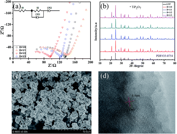 | ||
| Fig. 1 (a) AC impedance profiles; (b) XRD patterns of the LATP powders with different content of molten CO(NH2)2 and (c) SEM and (d) HR-TEM images of the LATP powders with D = 1/2. | ||
In addition, SEM images were recorded to investigate the morphologies of LATP powders calcined at 700 °C for 4 h with D = 1/2 (Fig. 1c). It can be observed that the particles are distributed homogeneously. The well-distributed particles would enable the formation of a compact pellet and then, contribute to reduce the grain boundary impedance.30 As shown in Fig. 1d, the lattice fringe of LATP powders with D = 1/2 can be clearly observed, implying that the product has a good crystallinity. The lattice spacing is 0.4 nm, which is attributed to the lattice distance between two [104] crystal planes of LATP.30
In order to acquire the optimum calcination temperature of the LATP powders, we examined the effects of calcination temperature ranging from 600 °C to 900 °C under the condition of D = 1/2. Impedance of the LATP powders at different calcination temperature was measured by pressing them into a pellet and then, calcined at 800 °C for 12 h. Fig. 2a presents XRD patterns of LATP powders calcined at different temperatures. The XRD data, in more detail, is shown in Fig. S2.† The intensity of the diffraction peaks increased as the temperature elevated, indicating that the crystallinity of LATP samples was enhanced gradually. However, when the calcination temperature was 600 °C or 900 °C, some TiP2O7 impurity phases appear. In contrast, no impurity phases could be observed at the temperature of 700 °C or 800 °C. From the impedance profiles shown in Fig. 2b, it is observed that the impedance value varies significantly at different temperatures and the LATP powder calcined at 700 °C possesses the least resistance. Combining the results of density test summarized in Table S2,† the pellets for the LATP powders calcined at 700 °C possess the highest density. Therefore, the optimal calcination temperature of the powder was fixed at 700 °C.
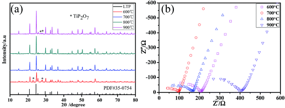 | ||
| Fig. 2 (a) XRD patterns and (b) AC impedance profiles for the LATP powders calcined at different temperatures. | ||
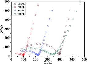
Subsequently, the effects of sintering temperature on LATP pellets were also investigated via the AC impedance and SEM technique. Fig. 3 shows the impedance profiles for the LATP pellets sintered at 750–900 °C for 12 h. The powders used before sintering are the LATP powders under the calcination temperature of 700 °C with D = 1/2. With the increase of sintering temperature, the total resistance decreased first and then increased, which was mainly caused by the changes in grain boundary impedance. As shown in Fig. 4, the fracture surfaces of LATP pellets were strongly dependent on sintering temperature. Some voids and cracks were observed for the sample sintered at 750 °C, 850 °C and 900 °C, which would increase the grain boundary impedance31 and then, reduce the ionic conductivity. However, for the pellet sintered at 800 °C, the particles closely connect to each other and the grain boundaries could not be clearly distinguished. Therefore, it can be observed that a suitable sintering temperature is central to the grain boundary impedance of LATP pellet.
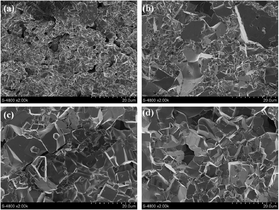 | ||
| Fig. 4 SEM images of the fracture surfaces in the LATP pellets sintered at various temperatures: (a) 750 °C; (b) 800 °C; (c) 850 °C; (d) 900 °C. | ||
The activation energy was obtained by testing a sample with the highest lithium ion conductivity. Fig. 5a presents the AC impedance spectra of LATP sample measured in the range of 40–120 °C. It can be observed that the conductivity gradually increases as the temperature moves to a higher value. Subsequently, as shown in Fig. 5b, the chart was drawn with log![[thin space (1/6-em)]](https://www.rsc.org/images/entities/char_2009.gif) σT as the ordinate, 1000/T as the abscissa. There is an excellent linear relationship between them, implying that the conductivity fits the Arrhenius equation σT = A(−Ea/KT) well, where σ is the conductivity, T is the absolute temperature, A is a pre-exponential factor, K is the Boltzmann's constant and Ea is activation energy for conduction. The activation energy calculated from the slope of the straight line is 0.29 eV, which is much lower than few of those reported in literature.32,33
σT as the ordinate, 1000/T as the abscissa. There is an excellent linear relationship between them, implying that the conductivity fits the Arrhenius equation σT = A(−Ea/KT) well, where σ is the conductivity, T is the absolute temperature, A is a pre-exponential factor, K is the Boltzmann's constant and Ea is activation energy for conduction. The activation energy calculated from the slope of the straight line is 0.29 eV, which is much lower than few of those reported in literature.32,33
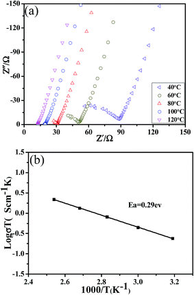 | ||
| Fig. 5 (a) The AC impedance spectra of LATP pellet with the highest conductivity measured in the range of 40–120 °C and (b) Arrhenius plot for the ionic conductivity of LATP pellet. | ||
3.2 Enhanced cyclic performance of solid state lithium ion battery with LATP as an electrolyte
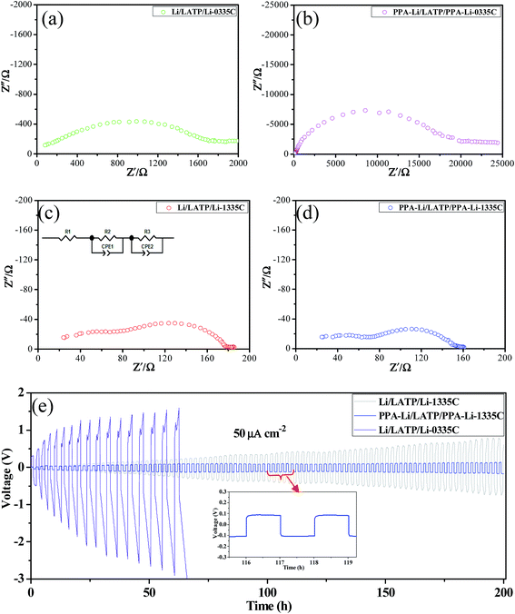
As indicated by Guo et al.,27 a stable artificial Li3PO4 SEI layer with a thickness of 200 nm could effectively inhibit lithium dendrite growth and reduce side reactions between lithium metal and organic electrolytes. In view of this, we intend to use this stable interface layer in the lithium anode to block the contact of LATP and lithium metal to enhance the stability between them. To certify the effect of Li3PO4 SEI layer on the improvement of the stability between LATP and metallic lithium, symmetric coin cells were prepared using the LATP pellets with the highest lithium ionic conductivity. The LATP pellets used were 1 mm thick with a surface area of 1.54 cm2. As shown in Fig. 6a–d, the resistance of the assembled symmetric coin cells was examined by electrochemical impedance spectroscopy at room temperature. Specifically, it is important to note that 1335C represents the addition of a small amount of liquid electrolyte at the interface between the LATP and the metallic lithium and 0335C indicates that no liquid electrolyte is added. Comparing a and b in Fig. 6, we can find that the impedance of the assembled symmetrical battery with no liquid electrolyte increased by more than ten times after special treatment of metallic lithium. The reason for this change is likely due to the interface impedance and lower ionic conductivity of Li3PO4, which is only 2.3 × 10⁻⁶ S cm−1 at room temperature.34 At the same time, this difference can also confirm the existence of Li3PO4 artificial SEI layer. However, such a huge impedance will hinder the normal charge and discharge of the battery, so adding a small amount of liquid electrolyte to reduce the impedance is necessary. The impedance diagram of the symmetrical battery with the liquid electrolyte added is shown in Fig. 6c and d. Clearly, the addition of a small amount of liquid electrolyte significantly reduced the impedance. Inset of Fig. 6c shows the equivalent circuit of the symmetrical battery with the liquid electrolyte. Each sample consists of two distinct arcs. The first arc represents grain boundary impedances of the LATP pellet and the second arc shows interfacial impedance between lithium metal and LATP. Thus, by dividing the diameter of the second arc by two, we can obtain the interfacial resistance on either side of the symmetric cells. Ultimately, we found that the interfacial resistance of one side of the symmetric PPA-Li/LATP/PPA-Li-1335C cell is 57.82 Ω cm−2, which is less than 69.93 Ω cm−2 obtained for the symmetric Li/LATP/Li-1335C cell.In addition to the impedance of symmetrical battery, we also have measured the stability of these symmetrical batteries by subjecting them to a constant direct-current of 50 μA cm−2. Fig. 6e presents the voltage profile of the battery cycled continuously for 200 h (2 h per cycle) at room temperature. We can observe that there is a rapid polarization for the Li/LATP/Li-0335C symmetrical battery, which indicates uneven ion transport through the interface caused by side reactions. With the addition of a small amount of liquid electrolyte, the polarization of Li/LATP/Li-1335C symmetrical battery is reduced, but still keeps increasing. This phenomenon could be possibly attributed to the following reasons: due to the reaction between lithium metal and organic electrolyte, a solid electrolyte interphase (SEI) layer could be formed on the lithium surface. To a certain extent, this layer of SEI could inhibit the occurrence of side reactions. However, the repeated breakage and repair of SEI layer35 would consume the liquid electrolyte gradually, leading to the drying up of the organic electrolyte, which results in the contact of LATP and metal lithium. Therefore, the addition of a little organic electrolyte could not prevent the occurrence of side reactions completely. Conversely, PPA-Li/LATP/PPA-Li-1335C symmetrical cell is much more stable. This is due to the artificial Li3PO4 SEI layer being stable during cycling without a breakage/repair mechanism, which has been proved by Guo et al.27 through their experiments.
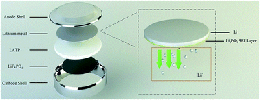
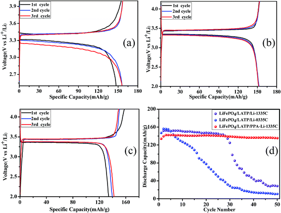
In addition, we assembled half-cells to further verify the effectiveness of this artificial Li3PO4 SEI layer. Herein, we investigated three types of half-cells: LiFePO4/LATP/Li-0335C cell, LiFePO4/LATP/Li-1335C cell and LiFePO4/LATP/PPA-Li-1335C cell. The architecture of LiFePO4/LATP/PPA-Li-1335C cell was designed as shown in Fig. 7. An artificial Li3PO4 SEI layer was formed on the surface of lithium metal to block contact between the LATP and the lithium metal, which would restrain the unfavorable reaction. The results of the galvanostatic charge/discharge tests are shown in Fig. 8a–d. Fig. 8a illustrates the charge and discharge curves of first three cycles for LiFePO4/LATP/Li-0335C battery. The polarization of the initial cycle reached about 150 mV and with the progress of the cycle, the discharge curve moved to lower potentials, displaying a significant polarization effect. When the organic electrolyte is added to modify the interface impedance, the polarization of the first circle for LiFePO4/LATP/Li-1335C battery decreased to 100 mV. This change is attributed to reduction of the interfacial impedance, which can be observed from Fig. 6. However, as the number of cycles increases, the polarization still increases gradually. Surprisingly, this trend is exactly opposite for LiFePO4/LATP/PPA-Li-1335C battery. As shown in Fig. 8c, with the progress of cycle, the polarization gradually reduced and stabilized at about 60 mV, which is much lower than the former polarization. The above-mentioned cell performance clearly shows the unique advantages of this special design.
Fig. 8d shows a comparison of cycling stability of aforementioned half-cells at the rate of 0.1C for 50 cycles. There is a slight improvement in the capacity of the first few cycles due to the activation process of the LiFePO4 material, which is a common phenomenon for lithium ion battery. As for LiFePO4/LATP/Li-0335C, the specific discharge capacity fades from 156.1 mA h g−1 to 10.9 mA h g−1 after 50 cycles and the capacity retention based on the maximum discharge capacity is only 7.0%. This poor cycle stability should be ascribed to the instability between lithium metal and LATP.36 After the organic electrolyte is added, the capacity of the LiFePO4/LATP/Li-1335C battery is reduced slightly in the first 28 cycles, but the battery still runs normally. Regrettably, the specific capacity of the battery decreased rapidly after the 29th cycle and only maintained at 27.6 mA h g−1 when on reaching the 50th cycle. Combined with the experimental results of the symmetrical battery tested earlier, the reason should be ascribed to the repeated breakage and repair of SEI layer that was generated from the reaction between lithium metal and organic electrolyte, resulting in the gradual consumption of the liquid electrolyte. As the electrolyte is completely consumed, metal lithium will come into contact with the LATP solid electrolyte. Side reactions will occur immediately, eventually leading to a sharp decline in battery performance. Importantly, due to the effective blocking of stable artificial Li3PO4 SEI layer, LiFePO4/LATP/PPA-Li-1335C cell exhibits a low capacity loss ratio and the capacity retention based on the maximum discharge capacity reaches 95.2% after 50 cycles, implying that adding an artificial Li3PO4 SEI layer is an effective way to improve the electrochemical properties of all solid state LIBs with LATP as an electrolyte.
4. Conclusions
In summary, pure Li1.3Al0.3Ti1.7(PO4)3 (LATP) ceramic powders have been successfully synthesized with CO(NH2)2 as a molten flux at a relatively lower temperature and were then used as the solid electrolyte material in lithium ion battery. Under the optimum preparation conditions (D = 1/2, the calcination temperature for LATP powder was 700 °C, the sintering temperature for LATP pellet was 800 °C), the sample possesses the highest total conductivity of 7.02 × 10⁻⁴ S cm−1 at room temperature and a lower activation energy of 0.29 eV. Simultaneously, we introduced an artificial Li3PO4 SEI layer to enhance the stability between LATP and metallic lithium. Symmetrical battery tests showed that the stability has been significantly improved and the assembled LiFePO4/LATP/PPA-Li-1335C cell showed excellent cycling stability. After 50 charge–discharge cycles, the capacity retention reaches 95.2%, which is much higher than that for the untreated samples. These results confirm that the addition of an artificial Li3PO4 SEI layer is an effective way to improve the stability of LATP against lithium anode and will promote the development of solid state LIBs with LATP as an electrolyte.Conflicts of interest
There are no conflicts to declare.Acknowledgements
This study was supported by National Key R&D Program of China (No. 2016YFB0901700).References
- C. Sun, J. Liu, Y. Gong, D. P. Wilkinson and J. Zhang, Nano Energy, 2017, 33, 363–386 CrossRef CAS.
- W. Mao, G. Ai, Y. Dai, Y. Fu, Y. Ma, S. Shi, R. Soe, X. Zhang, D. Qu and Z. Tang, J. Power Sources, 2016, 310, 54–60 CrossRef CAS.
- J. Xie and Q. Zhang, J. Mater. Chem. A, 2016, 4, 7091–7106 CAS.
- H.-G. Wang, S. Yuan, D.-L. Ma, X.-B. Zhang and J.-M. Yan, Energy Environ. Sci., 2015, 8, 1660–1681 CAS.
- H. Zhong, G. Wang, Z. Song, X. Li, H. Tang, Y. Zhou and H. Zhan, Chem. Commun., 2014, 50, 6768–6770 RSC.
- H. Tang, Y. Zhou, L. Zan, N. Zhao and Z. Tang, Electrochim. Acta, 2016, 191, 887–894 CrossRef CAS.
- C. Wang, Y. Yang, X. Liu, H. Zhong, H. Xu, Z. Xu, H. Shao and F. Ding, ACS Appl. Mater. Interfaces, 2017, 9, 13694–13702 CAS.
- C. Yu, L. van Eijck, S. Ganapathy and M. Wagemaker, Electrochim. Acta, 2016, 215, 93–99 CrossRef CAS.
- R. Tan, J. Yang, J. Zheng, K. Wang, L. Lin, S. Ji, J. Liu and F. Pan, Nano Energy, 2015, 16, 112–121 CrossRef CAS.
- N. Kamaya, K. Homma, Y. Yamakawa, M. Hirayama, R. Kanno, M. Yonemura, T. Kamiyama, Y. Kato, S. Hama and K. Kawamoto, Nat. Mater., 2011, 10, 682–686 CrossRef CAS PubMed.
- H. Zhong, C. Wang, Z. Xu, F. Ding and X. Liu, Sci. Rep., 2016, 6, 25484–25490 CrossRef CAS PubMed.
- E. Zhao, F. Ma, Y. Jin and K. Kanamura, J. Alloys Compd., 2016, 680, 646–653 CrossRef CAS.
- K. Chen, M. Huang, Y. Shen, Y. Lin and C. W. Nan, Electrochim. Acta, 2012, 80, 133–139 CrossRef CAS.
- F. Mizuno, A. Hayashi, K. Tadanaga and M. Tatsumisago, Adv. Mater., 2005, 17, 918–921 CrossRef CAS.
- J. Wei, H. Kim, D.-C. Lee, R. Hu, F. Wu, H. Zhao, F. Alamgir and G. Yushin, J. Power Sources, 2015, 294, 494–500 CrossRef CAS.
- A. Dumon, M. Huang, Y. Shen and C.-W. Nan, Solid State Ionics, 2013, 243, 36–41 CrossRef CAS.
- C. L. Tsai, V. Roddatis, C. V. Chandran, Q. Ma, S. Uhlenbruck, M. Bram, P. Heitjans and O. Guillon, ACS Appl. Mater. Interfaces, 2016, 8, 10617–10626 CAS.
- L. Huang, Z. Wen, M. Wu, X. Wu, Y. Liu and X. Wang, J. Power Sources, 2011, 196, 6943–6946 CrossRef CAS.
- Q. Ma, Q. Xu, C. L. Tsai, F. Tietz and O. Guillon, J. Am. Ceram. Soc., 2015, 99, 410–414 CrossRef.
- S. D. Jackman and R. A. Cutler, J. Power Sources, 2012, 218, 65–72 CrossRef CAS.
- J. Fu, Solid State Ionics, 1997, 96, 195–200 CrossRef CAS.
- K. M. Kim, D. O. Shin and Y.-G. Lee, Electrochim. Acta, 2015, 176, 1364–1373 CrossRef CAS.
- E. Zhao, F. Ma, Y. Guo and Y. Jin, RSC Adv., 2016, 6, 92579–92585 RSC.
- L. Gao, W. Jiang, W. Wei, J. Yan and Z. Tang, Mater. Lett., 2014, 131, 324–327 CrossRef CAS.
- L. Cheng, H.-J. Liu, J.-J. Zhang, H.-M. Xiong and Y.-Y. Xia, J. Electrochem. Soc., 2006, 153, 1472–1477 CrossRef.
- Z. Chang, Z. Chen, F. Wu, X.-Z. Yuan and H. Wang, Electrochim. Acta, 2009, 54, 6529–6535 CrossRef CAS.
- N. W. Li, Y. X. Yin, C. P. Yang and Y. G. Guo, Adv. Mater., 2016, 28, 1853–1858 CrossRef CAS PubMed.
- P. Zhang, H. Wang, Y.-G. Lee, M. Matsui, Y. Takeda, O. Yamamoto and N. Imanishi, J. Electrochem. Soc., 2015, 162, A1265–A1271 CrossRef CAS.
- F. Ma, E. Zhao, S. Zhu, W. Yan, D. Sun, Y. Jin and C. Nan, Solid State Ionics, 2016, 295, 7–12 CrossRef CAS.
- X. Liu, J. Tan, J. Fu, R. Yuan, H. Wen and C. Zhang, ACS Appl. Mater. Interfaces, 2017, 9, 11696–11703 CAS.
- S. Duluard, A. Paillassa, L. Puech, P. Vinatier, V. Turq, P. Rozier, P. Lenormand, P.-L. Taberna, P. Simon and F. Ansart, J. Eur. Ceram. Soc., 2013, 33, 1145–1153 CrossRef CAS.
- H. Yamada, D. Tsunoe, S. Shiraishi and G. Isomichi, J. Phys. Chem. C, 2015, 119, 5412–5419 CAS.
- Y. Yoon, J. Kim, C. Park and D. Shin, J. Ceram. Process. Res., 2013, 14, 563–566 Search PubMed.
- B. Xu, W. Li, H. Duan, H. Wang, Y. Guo, H. Li and H. Liu, J. Power Sources, 2017, 354, 68–73 CrossRef CAS.
- Y. Liu, D. Lin, P. Y. Yuen, K. Liu, J. Xie, R. H. Dauskardt and Y. Cui, Adv. Mater., 2017, 29, 1605531–1605538 CrossRef PubMed.
- L. Z. Huang, Z. Y. Wen, J. Jin and Y. Liu, J. Inorg. Mater., 2012, 27, 249–252 CrossRef CAS.
Footnote |
| † Electronic supplementary information (ESI) available. See DOI: 10.1039/c7ra09335g |
| This journal is © The Royal Society of Chemistry 2017 |

