
 Open Access Article
 This Open Access Article is licensed under a
 Creative Commons Attribution 3.0 Unported Licence
Cobalt sulfide supported on nitrogen and sulfur dual-doped reduced graphene oxide for highly active oxygen reduction reaction†
Ying Zhang‡
a,
Pingwei Li‡a,
Xuying Yina,
Ya Yanab,
Ke Zhana,
Junhe Yangab and
Bin Zhao *ab
*ab
aSchool of Materials Science and Engineering, University of Shanghai for Science and Technology, Shanghai 200093, China. E-mail: zhaobin@usst.edu.cn
bShanghai Innovation Institute for Materials, Shanghai 200444, China
First published on 27th October 2017
Abstract
Cobalt sulfide nanoparticles grown on nitrogen and sulfur dual-doped reduced graphene oxide sheets (Co–S/NS-rGO) were synthesized as an efficient electrocatalyst for the oxygen reduction reaction (ORR) by a facile one-step annealing process at 400–600 °C. The catalyst synthesized at 500 °C (Co–S/NS-rGO-500) exhibits the best ORR catalytic activity compared to the other samples, together with high four-electron selectivity and excellent stability in alkaline medium. Moreover, the Co–S/NS-rGO-500 composite also manifests good ORR activity and selectivity in acid solution. The facile synthesis approach and superior ORR performance in both alkaline and acid electrolytes make the Co–S/NS-rGO catalysts promising as an alternative to commercial Pt/C catalyst for fuel cells.
1. Introduction
On account of the impending global energy crisis, fuel cells have become attractive as a promising power source with high energy conversion efficiency, high power density, quiet operation and low emission.1,2 However, the high cost of common Pt-based electrocatalysts and sluggish kinetics of the oxygen reduction reaction (ORR) at the cathode are still the major limiting factors for commercialization of fuel cells.3,4 Therefore, development of inexpensive non-precious metal electrocatalysts that rival the ORR performance of Pt catalysts remains a big challenge.Over the past decades, tremendous efforts have been devoted to replacing Pt-based catalysts by employing heteroatom-doped carbon nanomaterials as potential candidates for ORR catalysts.5–9 Although nitrogen-doped (N-doped) graphene appears to be promising as a potential ORR electrocatalyst due to high catalytic activity and low cost,10,11 most mono-heteroatom doped carbon materials still show inferior activity to that of the Pt/C catalyst. More recently, dual-doped graphene with more than one heteroatom, such as P, N dual-doped, and S, N dual-doped graphene, has been proved to be more active for ORR than N-doped graphene because of the advantages of different heteroatoms in conjugated carbon backbone which can generate more active sites and the synergistic effect between the dopants.12,13 Besides, cobalt sulfides with different stoichiometric ratios have been previously explored as ORR catalysts and exhibit attractive electrocatalytic performance among all non-precious metal chalcogenides.14–17 However, the low electrical conductivity and the easy agglomeration of cobalt sulfides often result in the unsatisfactory ORR activities.14,15,18 Therefore, nanocomposite with cobalt sulfides grown on conductive graphene support appears to a promising strategy for active ORR catalyst. Recently, Dai's group synthesized Co1−xS nanoparticles on reduced graphene oxide (rGO) and found that the rGO supports facilitated growth of smaller Co1−xS nanoparticles, leading to enhanced surface area and active catalytic sites for ORR.19 Higgins et al. reported improved ORR performance of CoS2 octahedral nanoparticles on N and S co-doped graphene/carbon nanotubes (CoS2-CG) than unsupported CoS2 catalyst, and demonstrated the importance of carbon supports in formation of the single crystal CoS2 nanoparticles.20 Despite of these advances in cobalt sulfide based non-precious metal ORR catalysts, the catalytic activities and long-term stability of most materials are still lower than those of the commercial Pt/C.15,18–20 Furthermore, complicated preparation procedure also increase cost of the nanocomposite ORR catalysts. Therefore, it is highly desirable to develop cobalt sulfide/graphene composite catalysts with high activity using simple synthesis method.
Herein, we propose a facile one-step annealing process to synthesize cobalt sulfide nanoparticles supported on N, S dual-doped graphene (Co–S/NS-rGO) as an efficient ORR catalyst. Due to the homogeneous distribution of cobalt sulfide nanoparticles, N and S dual-doping, as well as their synergistic effects, the nanocomposite catalyst exhibits excellent ORR catalytic activity and high four-electron selectivity in alkaline and acid media.
2. Experimental
2.1 Preparation of Co–S/NS-rGO
Graphene oxide (GO) was used as a starting materials and made by a modified Hummers' method as described in literatures.19,20 In a typical synthesis, 20 mg ammonium thiocyanate (NH4SCN) and 5 mg cobalt acetate (Co(OAC)2) were firstly dissolved in 30 ml deionized water. Secondly, 20 mg GO was added into the precursor solution and ultrasonically dispersed for 2 h. Subsequently, the mixture was further stirred for additional 48 h to achieve a homogeneous dispersion solution. Then, the solution was freezing dried to obtain intermediate product. Finally, the intermediate product was annealed at a temperature ranging between 400–600 °C for 2 h in Ar atmosphere, and the obtained material is designated as Co–S/NS-rGO-T (where T stands for the annealing temperature). For comparison, nitrogen and sulfur dual-doped graphene (NS-rGO) was also prepared using the same method except the addition of cobalt acetate.2.2. Materials characterization
Morphology of the Co–S/NS-rGO was observed by field-emission scanning electron microscope (FE-SEM, FEI, Quanta FEG 450) operated at 20–30 kV. Microstructure of the samples was examined by high resolution transmission electron microscopy (HRTEM; JEOL JEM-2010). X-ray diffraction (XRD) was employed to analyze crystal structure of the samples and performed on a Bruker D8-Advance X-ray diffractometer using a Cu Kα radiation (λ = 0.154 nm). X-ray photoelectron spectroscopy (XPS, ESCALAB250Xi, Thermo Fisher) was carried out to evaluate chemical state and composition of the samples by using a Mg Kα source. Raman spectra was recorded with a 785 nm laser as excitation source using a Raman Station (PerkinElmer 400).2.3 Electrochemical measurements
Electrochemical performance of the Co–S/NS-rGO catalyst was measured at room temperature on an electrochemical workstation (CHI 760E, CH Instrument) in a conventional three-electrode cell. A platinum wire, a saturated-calomel electrode (SCE), and catalyst-coated glassy carbon (GC) electrode were used as counter electrode, reference electrode, and working electrode, respectively, in 0.1 M KOH or 0.5 M H2SO4 solution. To prepare the catalyst ink, 1.5 mg catalyst powder, 10 μl Nafion (Alfa, 5 wt%) and 190 μl ethanol were mixed by ultrasonication for at least 30 min. Subsequently, 10 μl catalyst ink solution was pipetted on the GC electrode surface and dried at room temperature. The typical catalyst loading on the GC electrode is about 0.38 mg cm−2.Cyclic voltammograms (CV), rotating disk electrode (RDE) and rotating ring-disk electrode (RRDE) techniques were utilized to characterize electrochemical activity of the catalysts. CVs were recorded in O2-saturated KOH (or H2SO4) electrolyte solution within the potential range from 0.2 V to −0.8 V (or from −0.2 V to 0.8 V), and the current–potential polarization curves of RDE studies were obtained at an electrode rotating speed of 900 rpm. Both CV and RDE experiments were performed at the potential scanning rate of 5 mV s−1. RRDE voltammograms were measured by setting the ring potential at 0.5 V in 0.1 M KOH or 1.0 V in 0.5 M H2SO4 solution, while scanning the disk potential at a rate of 5 mV s−1. All potentials reported in this work are calibrated to the reversible hydrogen electrode (RHE) according to the literatures.2,21
3. Results and discussion
The facile preparation process and the structure of the Co–S/NS-rGO composites are illustrated in Scheme 1. Briefly, NH4SCN and Co(OAC)2 are used as the nitrogen, sulfur and cobalt sources, respectively, which are mixed with GO in aqueous solution. Then, the dispersion solution is lyophilized to obtain the intermediate product. Subsequently, the dried mixture is annealed in Ar atmosphere to obtain the Co–S/NS-rGO composites. Since annealing temperature is known to be a key factor to influence the performance of the catalysts for ORR,21,22 the Co–S/NS-rGO composite catalyst are synthesized at various annealing temperatures to achieve the optimum electrocatalytic properties. | ||
| Scheme 1 Schematic illustration of the synthesis of Co–S/NS-rGO composite by one-step annealing. | ||
Crystal structure of the Co–S/NS-rGO composites synthesized at various temperatures was investigated by XRD. Interestingly, the annealing temperature was found to have significant influence on structure of the cobalt sulfide. As shown in Fig. 1, the broad peaks at about 25° and 43° correspond to the (002) and (100) diffraction of graphitic carbon, respectively, confirming the presence of rGO.23 For the sample annealed at 400 °C, the diffraction peaks at 32.3°, 36.4°, 39.9°, 46.6°, 55°, 60.2°, 62.7°, and 70.5° can be well assigned to cubic CoS2 phase (JCPDS no. 41-1471).21 When the annealing temperature is above 500 °C (both 500 and 600 °C), the CoS2 peaks disappear and the new diffraction peaks appeared at 30.8°, 35.4°, 46.9° and 54° are attributed to Co1−xS phase (JCPDS no. 42-0826) with hexagonal structure in space group P63/mmc (no. 194).19 Therefore, a phase transition from cubic to hexagonal takes place for the cobalt sulfide as the annealing temperature rises from 400 °C to over 500 °C.
 | ||
| Fig. 1 XRD patterns of the catalysts: (a) Co–S/NS-rGO-400, (b) Co–S/NS-rGO-500, (c) Co–S/NS-rGO-600. | ||
Since both CoS2 and Co1−xS have been reported to be active for ORR,2,20 the Co–S/NS-rGO composites fabricated here are expected to be good ORR electrocatalysts.
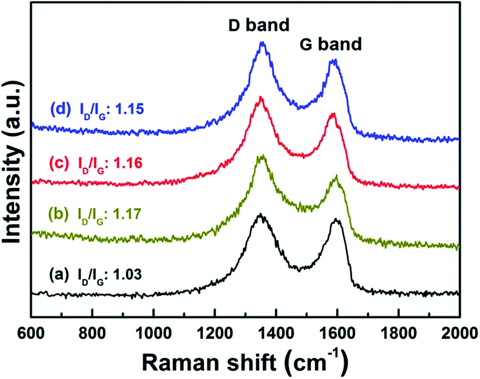
Structural information about the Co–S/NS-rGO was also obtained from Raman analysis. Fig. 2 shows Raman spectra of pristine GO and the Co–S/NS-rGO composites synthesized at various temperatures, which presents two characteristic Raman peaks. The G band at 1590 nm−1 originates from the sp2-hybridized graphitic carbon, whereas the D band at 1350 nm−1 is associated with disordered carbon in GO. The intensity ratio of D band (ID) and G band (IG) is often used as an index of defect levels in carbon materials.24,25 Pristine GO has an ID/IG ratio of 1.03, whereas the Co–S/NS-rGO composites demonstrate higher ID/IG ratios (around 1.15), which can be attributed to the imperfections induced by the heteroatom doping in the graphene structure.13,25,26 Interestingly, the ID/IG ratios decrease slightly with the increase in annealing temperature, indicating that the graphene structure is partially recovered at higher temperature.
 | ||
| Fig. 2 Raman spectra of GO (a) and the Co–S/NS-rGO catalysts: (b) Co–S/NS-rGO-400, (c) Co–S/NS-rGO-500, (d) Co–S/NS-rGO-600. | ||
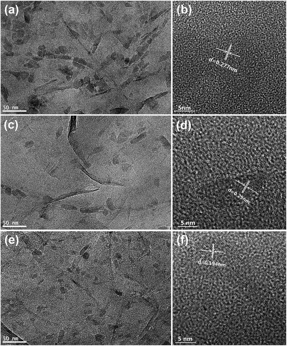
Morphology and microstructure of the Co–S/NS-rGO composites were further examined by TEM. Fig. 3 shows typical TEM images of the composites synthesized at various temperatures. Clearly, the cobalt sulfide nanoparticles are irregular in shape and uniformly distributed on the GO surface for the Co–S/NS-rGO-400 sample. Average size of the CoS2 nanoparticles is about 15–20 nm. And the lattice fringes with an interplanar spacing of 0.28 nm is in agreement with (200) plane of cubic CoS2 phase, as shown in the HR-TEM image (Fig. 2b). As the annealing temperature rises to above 500 °C, the size and shape of nanoparticles on rGO surface does not show obvious changes. The lattice fringes of 0.19 nm and 0.29 nm correspond to the (102) and (100) planes of the hexagonal Co1−xS phase, respectively, in good agreement with the XRD result.
 | ||
| Fig. 3 TEM and HR-TEM images of the catalysts synthesized at various temperatures: (a), (b) Co–S/NS-rGO-400; (c), (d) Co–S/NS-rGO-500; (e), (f) Co–S/NS-rGO-600. | ||
Doping of heteroatoms into graphene was firstly analyzed by energy dispersive X-ray spectroscopy (EDS) equipped on FE-SEM. The EDS spectrum (Fig. S1†) demonstrates the presence of N, S, Co, O and C elements in the as-synthesized Co–S/NS-rGO composites. As shown in the EDS elemental mapping of the Co–S/NS-rGO-500 (Fig. 4), N, S and Co elements disperse homogeneously on the rGO sheet, confirming the successful doping of N and S in graphene and the uniform distribution of the cobalt sulfide nanoparticles on rGO surface. XPS analysis was also carried out to further study surface chemical composition of the obtained Co–S/NS-rGO composites. Fig. 5a shows survey spectra for the samples synthesized at various temperatures. The peaks around 285, 399, 532 and 782 eV correspond to C 1s, N 1s, O 1s and Co 2p, respectively. And the characteristic peaks appeared at 164 and 228 eV are attributed to the presence of sulfur. Table 1 summarizes surface elemental composition of the various samples. The N and S contents are determined to be 8.5 and 4.6 at%, respectively, for the Co–S/NS-rGO-400 sample. With increasing the annealing temperature above 500 °C, the composite shows significant decrease in the contents of N and S.
 | ||
| Fig. 4 SEM image (a) and elemental mapping analysis (b–f) of the composite obtained at 500 °C. | ||
 | ||
| Fig. 5 (a) XPS survey spectra of the catalysts synthesized at various temperatures; high-resolution XPS spectra of the Co–S/NS-rGO-500 catalyst: (b) N 1s, (c) S 2p, and (d) Co 2p3/2. | ||
| Samples | Co (at%) | S (at%) | N (at%) | C (at%) | O (at%) |
|---|---|---|---|---|---|
| Co–S/NS-rGO-400 | 1.4 | 4.6 | 8.5 | 77.8 | 7.7 |
| Co–S/NS-rGO-500 | 1.1 | 2.5 | 5.7 | 81.4 | 9.3 |
| Co–S/NS-rGO-600 | 1.1 | 2.6 | 5.8 | 85.1 | 5.4 |
High-resolution XPS spectra can provide more insight on the chemical state of each component. As shown in Fig. 5b, the N 1s spectrum of the Co–S/NS-rGO-500 sample is deconvoluted into three peaks at 398.5, 399.6, and 401.1 eV, corresponding to pyridinic-N, pyrrolic-N, and graphitic-N, respectively.1,13,27,28 This provides further evidence that nitrogen has been doped in graphene matrix. Quantitative analysis from the N 1s spectra of the various samples (Fig. S2†) reveals that, as the annealing temperature rises, relative contents of the three N species change. The largest pyridinic-N content is achieved for the Co–S/NS-rGO-500 (55.3%), while graphitic-N increases and pyrrolic-N decreases with raising the temperature. In the high-resolution S 2p spectrum (Fig. 5c), the peak located at 162.5 eV is attributed to the Co–S bond, while the pair of peaks at 163.8 and 164.9 eV are assigned to 2p3/2 and 2p1/2 of thiophene–S (–C–S–C–) due to the spin–orbit coupling.2,20,29 The presence of thiophene–S reveals that the doped S atoms are directly bonded with two carbon atoms and defects of graphene.29 For all the composites obtained at various temperatures, the thiophene–S content is almost constant, over than 60 at%, suggesting the stable incorporation of sulfur atoms in graphene framework. It was worth noting that an obvious peak at 168.4 eV exists in the S 2p spectrum of the Co–S/NS-rGO, while the corresponding peak is absent for the NS-rGO (Fig. S3†), indicating covalent coupling between the cobalt sulfide nanoparticles and the NS-rGO through the –C–SOx–Co– bonding.30 The relative contents of N and S components are presented in Table 2 for the composites annealed at various temperatures. Moreover, Co 2p3/2 peak at 779.1 and 781.2 eV are assigned to CoIII and CoII, suggesting presence of the mixed oxidation state in the Co1−xS phase, consistent with the previous reports.31,32 And the Co–O peak appeared at 782.3 eV can be ascribed to surface adsorption of O2 or slight oxidation of the cobalt sulfide nanoparticles exposed to air, further demonstrating the strong adsorption ability of the cobalt sulfide nanoparticles for oxygen molecules, which is beneficial for good ORR catalyst.33,34
| Samples | N 1s | S 2p | ||||
|---|---|---|---|---|---|---|
| Pyridinic-N (%) | Pyrrolic-N (%) | Graphitic-N (%) | Co–S (%) | –C–S–C– (%) | SOx (%) | |
| Co–S/NS-rGO-400 | 35.6 | 48.8 | 15.6 | 24.6 | 61.5 | 13.9 |
| Co–S/NS-rGO-500 | 55.3 | 24.3 | 20.4 | 19.3 | 62.2 | 18.5 |
| Co–S/NS-rGO-600 | 50.4 | 21.6 | 28.0 | 19.2 | 63.7 | 17.1 |
The ORR activities of the Co–S/NS-RGO samples were firstly investigated by cyclic voltammetry in 0.1 M KOH solution at a potential scanning rate of 5 mV s−1. Compared with the featureless CVs obtained in N2-saturated solution, the CVs measured in O2-saturated electrolyte show pronounced oxygen reduction peaks for all the samples, indicating the obvious catalytic activity towards ORR (Fig. S3†). As shown in Fig. 6a, the ORR peak potential shifts from 0.786 to 0.836 and 0.799 V for the catalysts annealed at 400, 500 and 600 °C, respectively. The sample annealed at 500 °C exhibits the most positive peak potential, indicating the best ORR catalytic activity. Moreover, the ORR peak potential of 0.836 V is also more positive than those reported for Co/NS-CNT,2 G,N-GCNS,13 N-Co9S8/G,35 and CoS/NSGA,36 suggesting a more facile ORR process on this composite catalyst.
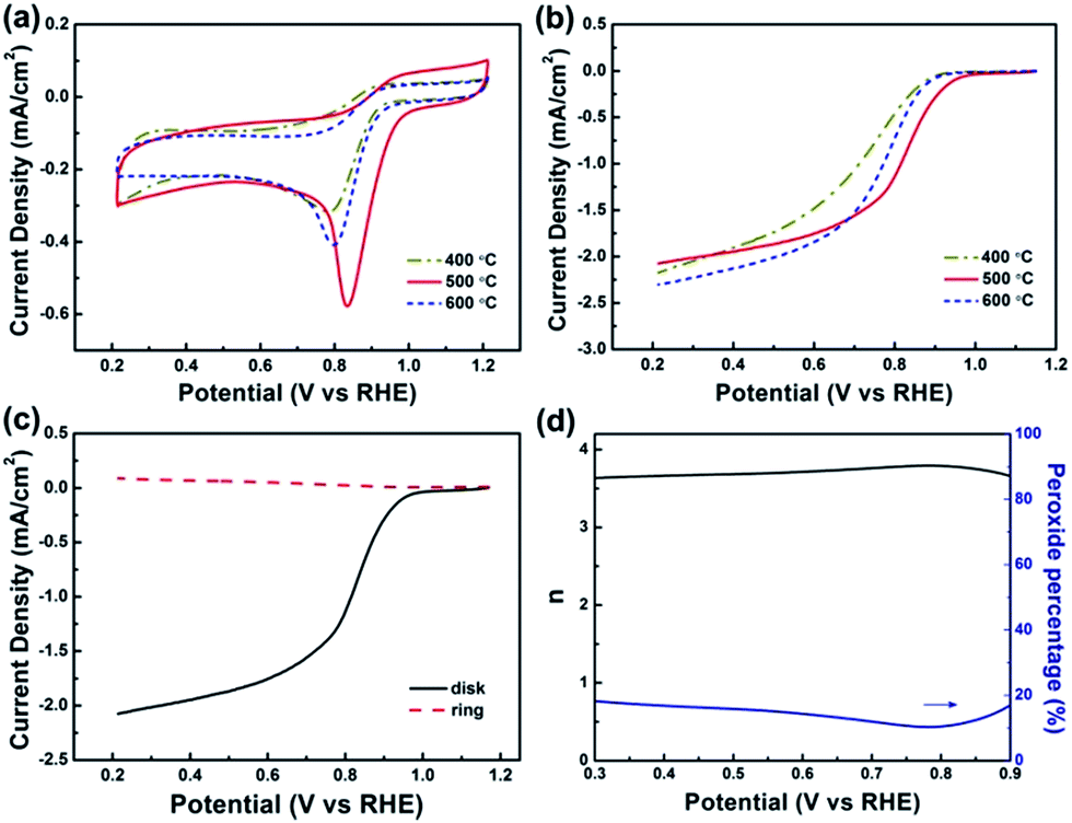 | ||
| Fig. 6 Typical CVs (a) and LSV curves (b) of the Co–S/NS-rGO catalysts obtained at various temperatures in O2-saturated 0.1 M KOH solution; (c) ring and disk current on Co–S/NS-rGO-500 catalyst at rotation rate of 900 rpm in O2-saturated 0.1 M KOH solution; (d) percentage of peroxide and the electron transfer number (n) of the Co–S/NS-rGO-500 catalyst based on the corresponding RRDE data in (c). | ||
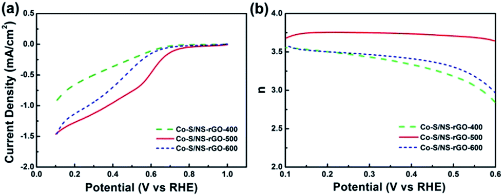
Rotating disk electrode (RDE) measurements were carried out to further examine the impact of annealing temperature on ORR performance of the Co–S/NS-rGO catalysts at a scan rate of 5 mV s−1 with a rotating rate of 900 rpm. Fig. 6b presents linear sweep voltammetry (LSV) curves of the Co–S/NS-rGO catalysts in O2-saturated 0.1 M KOH solution. Obviously, as the annealing temperature rises, the onset potential for ORR increases firstly from 0.903 V (400 °C) to 0.979 V (500 °C), and then decreases to 0.917 V (600 °C), whereas the half-wave potential shifts positively from 0.696 V (400 °C) to 0.811 V (500 °C), then shifts negatively to 0.756 V (600 °C). Therefore, from both the onset and half-wave potentials, the Co–S/NS-rGO-500 is determined to possess the highest catalytic activity towards ORR in KOH solution.
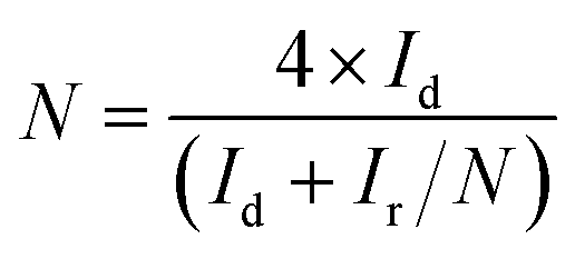
To gain further insight into the ORR process of the Co–S/NS-rGO catalyst, rotating ring-disk electrode (RRDE) measurements were conducted on the Co–S/NS-rGO-500 catalyst. Fig. 6c shows ring current and disk current of the catalyst in O2-saturated 0.1 M KOH solution at a potential scan rate of 5 mV s−1 and a rotating rate of 900 rpm. The ring current is far less than the disk current, indicating that H2O is the main product of ORR process of this sample. The number of electrons transferred in per oxygen molecular (n) and the percentage of peroxide yield (%HO2−) during ORR can be calculated by the following equation:2,13
 | (1) |
 | (2) |
The calculated electron transfer number and the HO2− yield from the experimental results are presented in Fig. 6d. Clearly, the n ranges between 3.61 and 3.79 in the potential range of 0.3–0.9 V, and the corresponding %HO2− yield is less than 18%, suggesting a four-electron dominated ORR process for this catalyst.
The superior ORR catalytic performance of the Co–S/NS-rGO-500 composite catalyst is associated with the bonding configuration of the heteroatoms in rGO. As revealed by the aforementioned XPS analysis, the pyridinic-N content reaches the maximum (55.3%) for the sample synthesized at 500 °C, indicating close correlation between the ORR activity and the pyridinic-N species.37 Meanwhile, the thiophene–S incorporated in graphene also plays important role in the ORR performance. Although the exact active sites are still controversial, it is established that N doping into carbon allows charge delocalization and generates a net positive charge on the adjacent carbon atoms due to the large electronegativity of N. The positively-charged carbon atoms may act as active sites for ORR to assist the adsorption of oxygen molecules.37,38 Moreover, the recent theoretical study reveals that S doping may introduce spin density or increase charge density of carbon atoms at graphene edges and thus promote the ORR activity.39–41 Therefore, when N and S are dual doped into graphene, the synergistic effect may induce larger spin and charge density than single doping, exhibiting higher ORR catalyst activity.
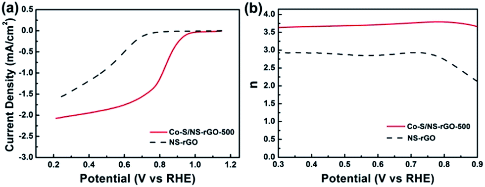
To clarify the role of the cobalt sulfide nanoparticles in ORR process, the Co–S/NS-rGO-500 composite catalyst was compared with the nitrogen and sulfur dual doped rGO (NS-rGO) fabricated using the same procedure at 500 °C. From the LSV curves in Fig. 7a, the NS-rGO shows an onset potential of 0.764 V, much negative than that of the Co–S/NS-rGO-500. And the electron transfer number of the NS-rGO sample, 2.13–2.93 over the potential range from 0.3 to 0.9 V, is also much lower than those of the Co–S/NS-rGO-500 catalyst (Fig. 7b). Therefore, it can be concluded that the Co1−xS nanoparticles on the NS-rGO play important role in the ORR performance of the catalyst, which not only provide more active sites to enhance the catalytic activity,19 but also facilitate the direct four-electron oxygen reduction process. Furthermore, covalent coupling between the Co1−xS nanoparticles and the NS-rGO is believed to be important for excellent ORR activity of the Co–S/NS-rGO-500. Since the Co1−xS nanoparticles are directly grown on rGO, good electrical contact facilitates charge transfer between oxygen molecules absorbed on Co1−xS active sites and the electrode. Besides, oxygen functional groups on rGO and defects induced by the heteroatom doping may promote heterogeneous nucleation of Co1−xS on rGO and lead to smaller particle size with higher surface area, which further contributes to enhanced ORR performance.19 It is worth noting that the onset potential of 0.979 V for the Co–S/NS-rGO-500 sample, although still inferior to that of the Pt/C catalyst, is higher than previously reported cobalt chalcogenide electrocatalysts in KOH electrolyte, such as Co3S4/G (0.92 V),18 Co1−xS/rGO (0.87 V),19 Co9S8/NHCS (0.97 V),33 CoS2/N,S-GO (0.97 V),32 and N-Co9S8/G (0.941 V),35 highlighting the excellent ORR catalytic activity of our composite catalyst.
 | ||
| Fig. 7 LSV curves for oxygen reduction (a) and the electron transfer number (b) of the Co–S/NS-rGO-500 and NS-rGO in O2-saturated 0.1 M KOH solution. | ||
Loading amount of the Co1−xS nanoparticles on graphene was optimized to further improve the ORR performance. Three Co–S/NS-rGO-500 samples were fabricated by using different amount of Co(OAC)2 as the precursor at 500 °C. As shown in Fig. 8, the ORR peak potential first shifts positively from 0.822 to 0.836 V, then shifts negatively to 0.722 V with increasing the Co(OAC)2 mass. Therefore, the Co–S/NS-rGO composite catalyst synthesized with 5.0 mg cobalt precursor manifests the highest catalytic activity towards ORR.
 | ||
| Fig. 8 Electrocatalytic stability of the Co–S/NS-rGO-500 catalysts in O2-saturated 0.1 M KOH solution at 0.68 V (vs. RHE) with a rotation rate of 1600 rpm. | ||
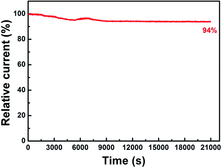
To evaluate long-term stability of the Co–S/NS-rGO-500 catalyst, current–time (i–t) chronoamperometry measurement was carried out at a constant potential of 0.68 V in the O2-saturated 0.1 M KOH solution with a rotating speed of 1600 rpm. As shown in Fig. 9, even after 21![[thin space (1/6-em)]](https://www.rsc.org/images/entities/char_2009.gif) 000 s, the Co–S/NS-rGO-500 catalyst exhibits a very slow attenuation with a high current retention (about 94%), which also outperforms the stability of CoxSy@C-1000,1 Co9S8/NHCS-900,32 CoS/NSGA,36 and Pt/C catalyst1 reported previously.
000 s, the Co–S/NS-rGO-500 catalyst exhibits a very slow attenuation with a high current retention (about 94%), which also outperforms the stability of CoxSy@C-1000,1 Co9S8/NHCS-900,32 CoS/NSGA,36 and Pt/C catalyst1 reported previously.
 | ||
| Fig. 9 CV curves of the Co–S/NS-rGO-500 catalysts synthesized with different amount of Co(OAC)2 in O2-saturated 0.1 M KOH solution. | ||
Since ORR in acid media is more challenging for non-precious metal catalysts, ORR performance of the Co–S/NS-rGO composites synthesized at various temperatures was also investigated by RDE and RRDE measurements in H2SO4 medium. Fig. 10a shows LSV curves of the Co–S/NS-rGO catalysts in O2-saturated 0.5 M H2SO4 solution. Clearly, with the increase of the annealing temperature, the onset potential firstly increases from 0.663 V (400 °C) to 0.791 V (500 °C), then shift negatively to 0.698 V (600 °C). A similar tendency is also found in the half-wave potential. Accordingly, the Co–S/NS-rGO-500 sample is proved to show the best catalytic activity in acid solution. Moreover, from RRDE tests, the electron transfer number of 3.64–3.75 is determined in the potential range of 0.1–0.6 V for the catalyst obtained at 500 °C (Fig. 10b), suggesting the good selectivity for four-electron reduction pathway in the acid solution. Although the catalytic activity and selectivity of the Co–S/NS-rGO-500 are still inferior to those of the Pt/C catalyst in acid media,42 the ORR activity with an onset potential of 0.791 V is among the best results for cobalt chalcogenide catalysts in acid electrolyte.19,42
 | ||
| Fig. 10 LSV curves (a) and the electron transfer number (b) of various Co–S/NS-rGO catalysts in O2-saturated 0.5 M H2SO4 solution at a scan rate of 5 mV s−1 and a rotation rate of 900 rpm. | ||
Overall, the prominent ORR performance of the Co–S/NS-rGO-500 catalyst in both alkaline and acid electrolyte is attributed to the following advantages. Firstly, dual-doping of N and S creates more active sites in graphene for ORR. Secondly, the Co1−xS nanoparticles with small size have higher surface area and expose more active sites. Thirdly, covalent coupling between the NS-rGO sheet and the Co1−xS nanoparticles facilitates charge transfer between the absorbed oxygen molecules and the electrode. Finally, close interaction and covalent bonding of the rGO with the Co1−xS nanoparticles prevents the detachment of the catalyst particles from the conducting graphene surface, which favors the long-term stability.
4. Conclusions
A high-efficiency Co–S/NS-rGO composite electrocatalyst was developed successfully from graphene oxide, NH4SCN and Co(OAC)2 precursors by a facile one-step annealing process. Depending on the temperature, CoS2 or Co1−xS nanoparticles were grown on graphene support, and nitrogen and sulfur were simultaneously incorporated into rGO. Due to the synergistic effect of the cobalt sulfide nanoparticles and the N, S dual-doped graphene, the Co–S/NS-rGO-500 catalyst exhibits excellent ORR activity in O2-saturated 0.1 M KOH solution with a peak potential of 0.836 V and an onset potential of 0.979 V, comparable to that of commercial Pt/C catalyst. And this catalyst manifests good four-electron selectivity and robust longterm stability. Besides, in 0.5 M H2SO4 medium, the Co–S/NS-rGO-500 also shows the best ORR performance among all samples. The facile synthesis method and the superior ORR performance of the Co–S/NS-rGO composites demonstrate great promise for application in fuel cells and metal-air batteries.Conflicts of interest
There are no conflicts to declare.Acknowledgements
This work was financially supported by the Natural Science Foundation of Shanghai (16ZR1423500) and The Program for Associate Professor of Special Appointment (Young Eastern Scholar) at Shanghai Institutions of Higher Learning (QD2016013).Notes and references
- B. Chen, R. Li, G. Ma, X. Gou, Y. Zhu and Y. Xia, Nanoscale, 2015, 7, 20674–20684 RSC.
- Y. Liu, B. Zhao, Y. Zhang, H. Zhang, K. Zhan, J. Yang and J. Li, RSC Adv., 2016, 6, 32676–32684 RSC.
- M. Shen, C. Ruan, Y. Chen, C. Jiang, K. Ai and L. Lu, ACS Appl. Mater. Interfaces, 2015, 7, 1207–1218 CAS.
- W. Choi, G. Yang, S. L. Kim, P. Liu, H. J. Sue and C. Yu, J. Power Sources, 2016, 313, 128–133 CrossRef CAS.
- F. Jaouen, E. Proietti, M. Lefevre, R. Chenitz, J.-P. Dodelet, G. Wu, H. T. Chung, C. M. Johnston and P. Zelenay, Energy Environ. Sci., 2011, 4, 114–130 CAS.
- L. Zhang and Z. Xia, J. Phys. Chem. C, 2011, 115, 11170–11176 CAS.
- S. Chen, J. Bi, Y. Zhao, L. Yang, C. Zhang, Y. Ma, Q. Wu, X. Wang and Z. Hu, Adv. Mater., 2012, 24, 5593–5597 CrossRef CAS PubMed.
- K. Gong, F. Du, Z. Xia, M. Durstock and L. Dai, Science, 2009, 323, 760–764 CrossRef CAS PubMed.
- J. P. Paraknowitsch, Energy Environ. Sci., 2013, 6, 2839–2855 CAS.
- L. Qu, Y. Liu, J. B. Baek and L. Dai, ACS Nano, 2010, 4, 1321–1326 CrossRef CAS PubMed.
- L. Lai, J. R. Potts, D. Zhan, L. Wang, C. K. Poh, C. Tang, H. Gong, Z. Shen, J. Lin and R. S. Ruoff, Energy Environ. Sci., 2012, 5, 7936–7942 CAS.
- J. Liang, Y. Jiao, M. Jaroniec and S. Z. Qiao, Angew. Chem., Int. Ed., 2012, 51, 11496–11500 CrossRef CAS PubMed.
- R. Li, Z. Wei and X. Gou, ACS Catal., 2015, 5, 4133–4142 CrossRef CAS.
- Y. Feng, T. He and N. Alonsovante, Chem. Mater., 2008, 20, 26–28 CrossRef CAS.
- Y. X. Zhou, H. B. Yao, Y. Wang, H. L. Liu, M. R. Gao, P. K. Shen and S. H. Yu, Chem.–Eur. J., 2010, 16, 12000–12007 CrossRef CAS PubMed.
- M. R. Gao, Y. F. Xu, J. Jiang and S. H. Yu, Chem. Soc. Rev., 2013, 44, 2986–3017 RSC.
- Q. Liu and J. Zhang, CrystEngComm, 2013, 15, 5087–5092 RSC.
- N. Mahmood, C. Zhang, J. Jiang, F. Liu and Y. Hou, Chem.–Eur. J., 2013, 19, 5183–5190 CrossRef CAS PubMed.
- H. Wang, Y. Liang, Y. Li and H. Dai, Angew. Chem., Int. Ed., 2011, 50, 10969–10972 CrossRef CAS PubMed.
- D. Higgins, F. M. Hassan, H. S. Min, J. Y. Choi, M. A. Hoque, U. L. Dong and Z. Chen, J. Mater. Chem. A, 2015, 3, 6340–6350 CAS.
- Z. Luo, B. Zhao, Y. Liu, H. Zhang, Z. Tang, J. Li and J. Yang, Electrochim. Acta, 2015, 161, 72–79 CrossRef CAS.
- L. Lin, Q. Zhu and A. W. Xu, J. Am. Chem. Soc., 2014, 136, 11027–11033 CrossRef CAS PubMed.
- Y. X. Wang, S. L. Chou, H. K. Liu and S. X. Dou, Carbon, 2013, 57, 202–208 CrossRef CAS.
- B. Zhao, L. Zhang, X. Wang and J. Yang, Carbon, 2012, 50, 2710–2716 CrossRef CAS.
- Y. Zheng, Y. Jiao, L. Ge, M. Jaroniec and S. Z. Qiao, Angew. Chem., Int. Ed., 2013, 125, 3192–3198 CrossRef.
- X. Gu, C. J. Tong, C. Lai, J. Qiu, X. Huang, W. Yang, B. Wen, L. M. Liu, Y. Hou and S. Zhang, J. Mater. Chem. A, 2015, 3, 16670–16678 CAS.
- J. Sanetuntikul, C. Chuaicham, Y. Choi and S. Shanmugam, J. Mater. Chem. A, 2015, 3, 15473–15481 CAS.
- J. Sanetuntikul and S. Shanmugam, Nanoscale, 2015, 7, 7644–7650 RSC.
- S. Gao, L. Li, K. Geng, X. Wei and S. Zhang, Nano Energy, 2015, 16, 408–418 CrossRef CAS.
- W. Yan, X. Cao, J. Tian, C. Jin, K. Ke and R. Yang, Carbon, 2016, 99, 195–202 CrossRef CAS.
- J. Zhu, Z. Ren, S. Du, Y. Xie, J. Wu, H. Meng, Y. Xue and H. Fu, Nano Res., 2017, 10, 1819–1831 CrossRef CAS.
- P. Ganesan, M. Prabu, J. Sanetuntikul and S. Shanmugam, ACS Catal., 2015, 5, 3625–3637 CrossRef CAS.
- J. Wang, L. Li, X. Chen, Y. Lu and W. Yang, J. Mater. Chem. A, 2016, 4, 11342–11350 CAS.
- Q. Wang, L. Jiao, H. Du, Y. Si, Y. Wang and H. Yuan, J. Mater. Chem., 2012, 22, 21387–21391 RSC.
- S. Dou, L. Tao, J. Huo, S. Wang and L. Dai, Energy Environ. Sci., 2016, 9, 1320–1326 CAS.
- Z. Luo, C. Tan, X. Zhang, J. Chen, X. Cao, B. Li, Y. Zong, L. Huang, X. Huang and L. Wang, Small, 2016, 12, 5920–5926 CrossRef CAS PubMed.
- S. Yang, L. Zhi, K. Tang, X. Feng, J. Maier and K. Mullen, Adv. Funct. Mater., 2012, 22, 3634–3640 CrossRef CAS.
- S. Bag, B. Mondal, A. K. Das and C. R. Raj, Electrochim. Acta, 2015, 163, 16–23 CrossRef CAS.
- J. Xu, G. Dong, C. Jin, M. Huang and L. Guan, ChemSusChem, 2013, 6, 493–499 CrossRef CAS PubMed.
- Z. Cui, S. Wang, Y. Zhang and M. Cao, J. Power Sources, 2014, 259, 138–144 CrossRef CAS.
- I. Y. Jeon, S. Zhang, L. Zhang, H. J. Choi, J. M. Seo, Z. Xia, L. Dai and J. B. Baek, Adv. Mater., 2013, 25, 6138–6145 CrossRef CAS PubMed.
- W. Gu, L. Hu, W. Hong, X. Jia, J. Li and E. Wang, Chem. Sci., 2016, 7, 4167–4173 RSC.
Footnotes |
| † Electronic supplementary information (ESI) available. See DOI: 10.1039/c7ra09231h |
| ‡ These authors contributed equally to this work. |
| This journal is © The Royal Society of Chemistry 2017 |