DOI:
10.1039/C7RA09179F
(Paper)
RSC Adv., 2017,
7, 49125-49132
An ambipolar 3,3′-dimethyl-9,9′-bianthracene derivative as a blue host material for high-performance OLEDs†
Received
19th August 2017
, Accepted 28th September 2017
First published on 20th October 2017
Abstract
A new ambipolar deep blue fluorophore with a non-donor–acceptor structure, MBAn-(4)-tBu (10,10′-bis-(4-tert-butyl-phenyl)-3,3′-dimethyl-9,9′-bianthracene), was designed and synthesized based on 3,3′-dimethyl-9,9′-bianthracene. The twisted conformation of the two anthracene units and the bulky end group substituted with a tert-butyl group in MBAn-(4)-tBu prevented π-conjugation effectively. In particular, MBAn-(4)-tBu in a non-doped device exhibited a maximum external quantum efficiency (EQE) of 3.94% with Commission Internationale de l’Éclairage (CIE) coordinates of (0.16, 0.07) and a narrow full width at half maximum of 49 nm, which was close to the CIE of high definition television standard blue. Furthermore, MBAn-(4)-tBu worked as an excellent fluorescent host for BD1 and DSA-ph dopants to obtain high performance OLEDs with excellent EQEs of 5.26% and 6.96%, respectively. These results demonstrate that the ambipolar 3,3′-dimethyl-9,9′-bianthracene molecule with a non-donor–acceptor structure is advantageous for the fabrication of highly efficient blue fluorescent OLEDs.
1. Introduction
Organic light-emitting devices (OLEDs) receive special attention for their commercial applications in flat-panel displays and solid-state lighting, attributed to their advantages of higher brightness, greater adaptability, longer life and greater energy efficiency.1–4 For full-color displays and high quality white light emissions, we require primary RGB (red, green and blue) emissions of relatively equal stability, efficiency and color purity. However, the development of a highly efficient and stable deep blue emitter needs to satisfy the required Commission Internationale de l’Éclairage (CIE) coordinates (x, y) = (0.14, 0.08), defined by the National Television System Committee (NTSC), and is essential in white OLEDs as one of the three basic colors and also as the host for both green and red emitters in doped devices. The performance of blue OLEDs is often retarded by the intrinsic wide band gap and stability problem of blue emitting materials,5,6 because the π-conjugation of the organic molecules must be strictly confined. This will then induce luminescence, charge-carrier injection/transportation and stability problems in OLEDs. Donor–acceptor (D–A)-type fluorophores have received considerable interest because of their high fluorescence quantum yields, due to the effective radiative decay of their excited intramolecular charge-transfer (ICT) state and impressive ambipolar charge-transporting properties for their constituent hole and electron-transporting moieties,7–12 which may solve the above problems and thus tremendously enhance the electroluminescence (EL) efficiencies of fluorescent OLEDs. However, deep blue OLEDs still suffer from low fluorescence quantum yields due to bipolar quenching, as well as large bathochromic shifts for the enlarged π-conjugation of D–A type fluorophores. Based on twisted 9,9′-bianthracene, which can break the local π-conjugation,13–21 Liu et al. previously developed a 9,9′-bianthracene-cored molecule featuring twisted ICT (TICT) to enhance radiative exciton generation for highly efficient deep blue OLEDs with an EQE of 3.9%.15 To further develop the properties of 9,9′-bianthracene-cored derivatives, we have synthesized a series of fluorinated and tert-butylated bianthracene derivatives, and used these compounds to serve as blue materials for high-performance fluorescent OLEDs with TICT excited states.16–20
In this work, we report a new deep blue fluorophore, MBAn-(4)-tBu (10,10′-bis-(4-tert-butyl-phenyl)-3,3′-dimethyl-9,9′-bianthracene), which has a non-D–A structure instead of the conventional D–A structure, which was derived from BAn-(4)-tBu, reported by our group. The 3,3′-dimethyl-9,9′-bianthracene (MBAn) moiety of MBAn-(4)-tBu could enhance the steric hindrance from the strong repulsion between the neighboring hydrogen atoms of anthracene and those of the tert-butyl group, simultaneously suppressing the intermolecular interactions and maintaining a high efficiency in the solid state. MBAn-(4)-tBu exhibited good thermal stability and an ambipolar transporting nature. Compared to pure blue-emitting BAn-(4)-tBu, the non-doped MBAn-(4)-tBu device showed better performance with a higher EQE of 3.94% and a deep blue emission at the CIE coordinates of (0.16, 0.07). In particular, MBAn-(4)-tBu worked as an excellent fluorescent host for BD1 (6,12-bis{[N-(3,4-dimethylphenyl)-N-(2,4,5-trimethylphenyl)]amino}chrysene) and DSA-ph (1-4-di-[4-(N,N-diphenyl)amino]styryl-benzene) dopants to obtain high-performance OLEDs with excellent EQEs of 5.26% and 6.96%, respectively. It shows great potential as a highly efficient blue host material for OLEDs.
2. Experimental
2.1 Materials and measurements
All reagents and solvents were used as purchased from commercial sources without further purification. 9,9′-Bi(2,2′-bimethyl)anthracene and 10,10′-bibromo-3,3′-dimethyl-9,9′-bianthracene were synthesized according to the literature.22,23 1H NMR spectra were recorded on a Bruker 400 MHz NMR spectrometer. Thermogravimetric analysis (TGA) and differential scanning calorimetry (DSC) were carried out on a STA 409 PC instrument at a heating rate of 10 °C min−1 under argon. Photoluminescence (PL) and absorption spectra were recorded on a HORIBA Jobin Yvon FluoroMax-4 spectrophotometer and a Unico UV-2600 PCS spectrophotometer, respectively. Photoluminescence quantum yields (PLQYs) were measured with an Absolute PL quantum yield spectrometer, C11347-11 (Hamamatsu, Japan). Cyclic voltammetry (CV) was performed using a CHI 660E electrochemical workstation at a scan rate of 100 mV s−1. All experiments were carried out in a three-electrode compartment cell with a Pt-sheet counter electrode, a glassy carbon working electrode and a Pt-wire reference electrode. The supporting electrolyte used was 0.1 M tetrabutylammonium hexafluorophosphate ([Bu4N]ClO4) solution in dry acetonitrile. The cell containing the solution of the sample (1 mM) and the supporting electrolyte was purged with nitrogen gas thoroughly before scanning for its oxidation and reduction properties. Ferrocene was used for potential calibration in each measurement. The potential was reported relative to the ferrocene–ferrocenium (Fc/Fc+) couple, whose onset potential was +0.13 V relative to the reference electrode. The oxidation potential was determined by taking the onset of the anodic potentials. The HOMO and LUMO values were estimated using the following equations: EHOMO = −e(EonOX + 4.8 eV) and ELUMO = EHOMO + Eg, where 4.8 eV is the energy level of ferrocene below the vacuum level and Eg is calculated from the absorption spectra.
2.2 Device fabrication and characterization
The devices were fabricated using thermal evaporation technology. Before device fabrication, the ITO glass substrates were cleaned with ultrasonication in acetone and isopropyl alcohol (IPA), exposed to a UV–ozone flux for 10 min, and finally transferred to a vacuum deposition system with a rate of organic compound deposition of 0.8–1.0 Å s−1. The cathode composed of LiF (1 nm) and aluminum (120 nm) was sequentially deposited onto the substrate under a base pressure lower than 1 × 10⁻³ Pa. The thickness of each layer was determined by a quartz thickness monitor. The effective size of the OLED was 14 mm2. The voltage–current density (V–J) and voltage–brightness (V–L) as well as the current density–current efficiency (J–ηc) and current density–power efficiency (J–ηp) curve characteristics of the devices were measured with a Keithley 2602 SourceMeter under ambient conditions. All measurements were carried out at room temperature under ambient conditions.
2.3 Synthesis of 10,10′-bis-(4-tert-butyl-phenyl)-3,3′-dimethyl-9,9′-bianthracenyl (MBAn-(4)-tBu)
THF (30 mL) and a 2.0 M aqueous solution of K2CO3 (10 mL) were added to a flask containing MBAn-(2)-Br (2.25 mmol), [4-(tert-butyl)phenyl]boronic acid (6 mmol) and Pd(PPh3)4 (0.225 mmol) under nitrogen. The reaction mixture was heated to reflux and maintained at this temperature for 24 h. When the reaction came to an end (determined by thin layer chromatography), water was added to quench the reaction. The product was then extracted with CH2Cl2, washed with brine and dried over anhydrous MgSO4, then concentrated by evaporating off the solvent for further purification by column chromatography on silica gel, with the solvent as the mobile phase. MBAn-(4)-tBu was obtained as a pale yellow powder. Yield: 96%. Tm = 407 °C. 1H NMR (CDCl3, 400 MHz): δ 1.56 (m, 18H), 2.15–2.37 (s, 6H), 6.77–6.98 (m, 4H), 7.01–7.17 (m, 6H), 7.37–7.83 (m, 12H). Anal. calcd (%) for C50H46: C, 92.83; H, 7.17. Found: C, 93.02; H, 6.98.
3. Results and discussion
3.1 Synthesis, structural characterization and theoretical computations
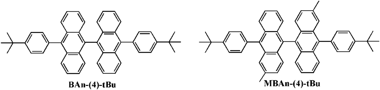
Scheme S1 in the ESI† summarizes the synthetic routes to the 3,3′-dimethyl-9,9′-bianthracene-based blue material, MBAn-(4)-tBu. Three reaction steps were involved in the synthesis process, including a Suzuki-coupling reaction between [4-(tert-butyl)phenyl]boronic acid and brominated 3,3′-dimethyl-9,9′-bianthracene to obtain MBAn-(4)-tBu. The synthesized blue material was purified using silica gel column chromatography as the wet process and vacuum sublimation as the dry process in succession. MBAn-(4)-tBu, with two additional methyl groups in the bianthracene core, inherits the orthogonal bianthracene architecture feature of BAn-(4)-tBu, as reported previously in our work (Fig. 1).20 The frontier molecular orbital energy level and the optimized geometry of MBAn-(4)-tBu were calculated using density functional theory (DFT) with the Gaussian 09 program (Fig. S1†). For both MBAn-(4)-tBu and BAn-(4)-tBu, the molecular orbitals of the two adjacent planar anthracene units are independent of each other, and each of the highest occupied molecular orbitals (HOMOs) and lowest unoccupied molecular orbitals (LUMOs) are energetically degenerate, which effectively prevents the uninterrupted π-conjugation of the whole molecule and the bathochromic shift of the emission, suppressing molecular packing in the solid state. Moreover, the sufficiently large LUMO–HOMO overlap should give a highly emissive ICT excited state, as demonstrated by its solvatochromic effects (see Fig. 4).
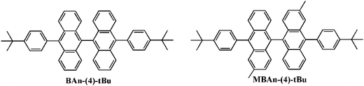 |
| | Fig. 1 Structures of BAn-(4)-tBu and MBAn-(4)-tBu. | |
3.2 Thermal and electrochemical properties
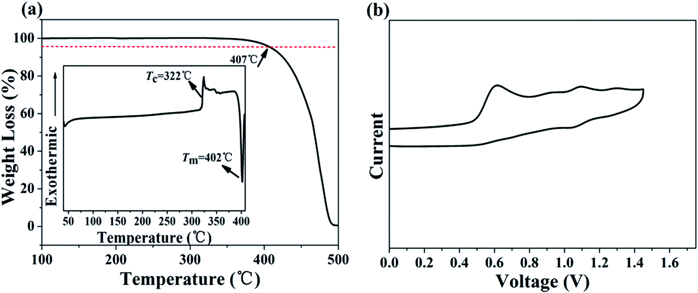
The thermal properties of MBAn-(4)-tBu were characterized by TGA and DSC measurements. The onset decomposition temperature (Td) at 5% weight loss upon heating during the TGA of MBAn-(4)-tBu was 407 °C (Fig. 2a), which was much higher than that of some other bianthracene derivatives, BAn and BAn-(4)-tBu.20,24 However, it did not exhibit a glass transition up to the melting point (Tm = 402 °C), even though the compound was heated to 420 °C. The high stability of the amorphous glass state of the compound is attributed to the non-coplanar geometry of the molecular structure,15,16 demonstrating that the perpendicular-type 3,3′-dimethyl-9,9′-bianthracene moiety and the bulky tert-butyl group improve the thermal stability efficiently. Therefore, thermal analyses indicate that this chromophore is thermally stable and suitable for vapor deposition in OLED fabrication. CV studies were performed to calculate the HOMO and LUMO values for MBAn-(4)-tBu. A trace of the CV measurement of MBAn-(4)-tBu is shown in Fig. 2b. From the oxidation onset potential, the HOMO energy level of MBAn-(4)-tBu is estimated to be −5.3 eV, and the LUMO energy level of MBAn-(4)-tBu is calculated to be −2.4 eV from the HOMO level and the energy gap (Eg), determined from the onset of the absorption spectra. The experimental HOMO value was almost in agreement with the calculated value (−5.0 eV).
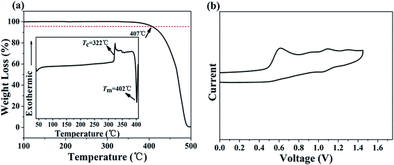 |
| | Fig. 2 (a) TGA curve (inset: DSC curve) of MBAn-(4)-tBu. (b) CV measurement of MBAn-(4)-tBu in CH3CN. | |
3.3 Photophysical properties
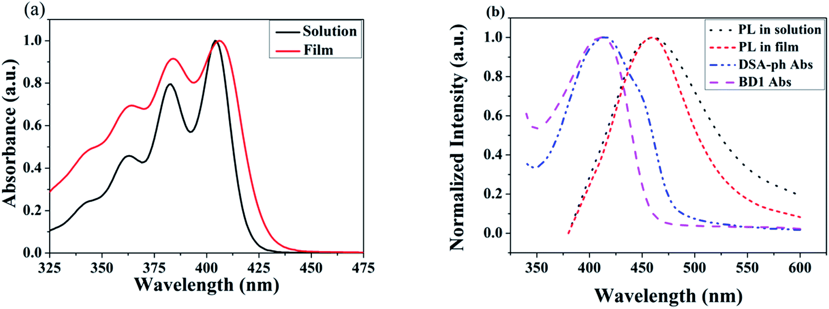
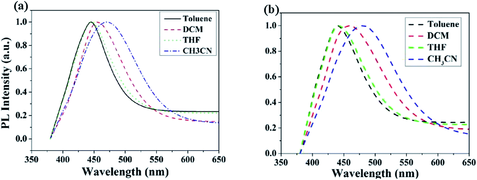
The UV-vis absorption and PL spectra of MBAn-(4)-tBu are shown in Fig. 3. A summary of the precise photophysical data of the compound is also given in the ESI, Table S1.† MBAn-(4)-tBu had four major UV absorption peaks at 344, 363, 384 and 404 nm in CH2Cl2 solution, as shown in Fig. 3a. These UV-vis peaks, with a characteristic vibrational pattern, were attributed to the π–π* transitions of the isolated anthracene core. The degree of redshift from the absorption peaks of the spin-coated thin film was only 2 nm, indicating that the extremely twisted and non-coplanar geometry and the peripheral tert-butyl phenyl groups could effectively suppress the possible intermolecular interactions.25 The energy gap (Eg) of MBAn-(4)-tBu was estimated to be approximately 2.9 eV from the absorption edge of 430 nm. It is worth noting that the profile of the thin film PL spectrum shows almost no redshift, with a significantly narrower FWHM (full width at half maximum) than that of the dilute solution of MBAn-(4)-tBu (Fig. 3b). This can be attributed to the greater steric hindrance of MBAn-(4)-tBu, which leads to an increase in non-planarity and prevents close molecular stacking in the solid film. Fig. 3b shows that the emission spectra of the host material, MBAn-(4)-tBu, overlap with the absorption spectra of the dopant materials (BD1 and DSA-ph). Presumably, DSA-ph (2.7 eV) can more effectively accept energy from the host material (MBAn-(4)-tBu) through Förster-type energy transfer than BD1 (3.2 eV).24 In addition, the absolute photoluminescence quantum yield (PLQY) of MBAn-(4)-tBu determined in THF was 0.57. MBAn-(4)-tBu demonstrates obvious solvatochromic shifts with an increase in solvent polarity, indicating that the emissive state of the material has typical charge transfer (CT) character (Fig. 4). From low-polarity toluene to high-polarity acetonitrile, the fluorescence of MBAn-(4)-tBu exhibited obvious solvatochromic effects with the increase in solvent polarity, and the total redshift of 40 nm is much larger than that of BAn-(4)-tBu (25 nm). These shifts suggest that the proportion of CT character in the S1 state of MBAn-(4)-tBu is certainly higher than that in BAn-(4)-tBu, and vice versa, the proportion of LE character in MBAn-(4)-tBu is clearly lower than that in BAn-(4)-tBu. Furthermore, the PL spectra continuously broadened with increasing solvent polarity. The larger shift and broader emission band in polar solvents, which is commonly consistent with the larger dipole moment of the CT state, indicate that the LE state of MBAn-(4)-tBu possesses a stronger CT state characteristic, involving the TICT mechanism of the MBAn core, than that of BAn-(4)-tBu with a 9,9′-bianthracene core (BAn).26,27
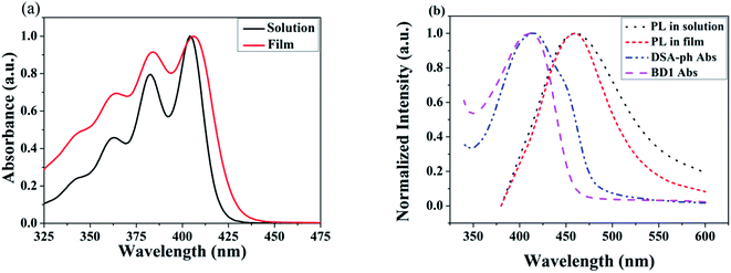 |
| | Fig. 3 UV-vis absorption spectra (a), and PL spectra of MBAn-(4)-tBu and absorption spectra of DSA-ph and BD1 (b). | |
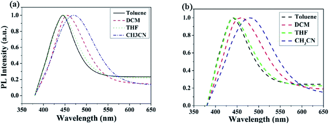 |
| | Fig. 4 PL spectra of BAn-(4)-tBu (a) and MBAn-(4)-tBu (b) in various solvents. | |
3.4 Ambipolar charge injection/transport properties
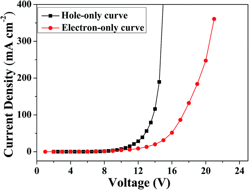
The ambipolar charge injection/transport properties of MBAn-(4)-tBu were identified using single-carrier devices. Two single-carrier devices were therefore fabricated using the following configurations: ITO/HAT-CN (5 nm)/TAPC (40 nm)/MBA-(4)-tBu (30 nm)/TAPC (40 nm)/Al (hole-only device) and ITO/TPBi (40 nm)/MBA-(4)-tBu (30 nm)/TPBi (40 nm)/Liq (1 nm)/Al (electron-only device). To improve hole injection from the anode, we used HAT-CN (4,5,8,9,11-hexaazatriphenylenehexacarbonitrile) as a hole injection layer. TAPC (1,1-bis[4-[N,N-di(p-tolyl)amino]phenyl]cyclohexane) and TPBi (1,3,5-tris(N-phenylbenzimidizol-2-yl)-benzene) layers were used to prevent electron and hole injection from the cathode and anode, respectively.28–30 Fig. 5 shows the current density versus voltage curves of both devices. It is obvious that both devices can conduct a significant amount of current, indicating that MBAn-(4)-tBu is capable of transporting both electrons and holes and that it exhibits an ambipolar transporting nature, which is effective for balancing holes and electrons in the emitting layer (EML) based on MBAn-(4)-tBu. The mobilities were calculated by fitting the current to the model of the single-carrier space-charge-limited current (SCLC) method. MBAn-(4)-tBu displays a high hole mobility of 5.2 × 10⁻³ cm2 V−1 s−1, which exceeds that of the typical hole transport material, N,N′-bis(naphthalen-1-yl)-N,N′-bis(phenyl)benzidine (NPB), by more than one order of magnitude. MBAn-(4)-tBu also exhibits a high electron mobility of 7.3 × 10⁻⁴ cm2 V−1 s−1, which is 20 times greater than that of TPBi (3 × 10⁻⁵ cm2 V−1 s−1). The substantially lower electron current density than the hole curve at the same voltage level should be attributed to the high-lying LUMO energy level of MBAn-(4)-tBu.31
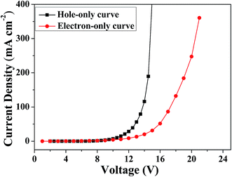 |
| | Fig. 5 Current density versus voltage characteristics of the hole-only and electron-only devices for MBAn-(4)-tBu. | |
3.5 Electroluminescence properties
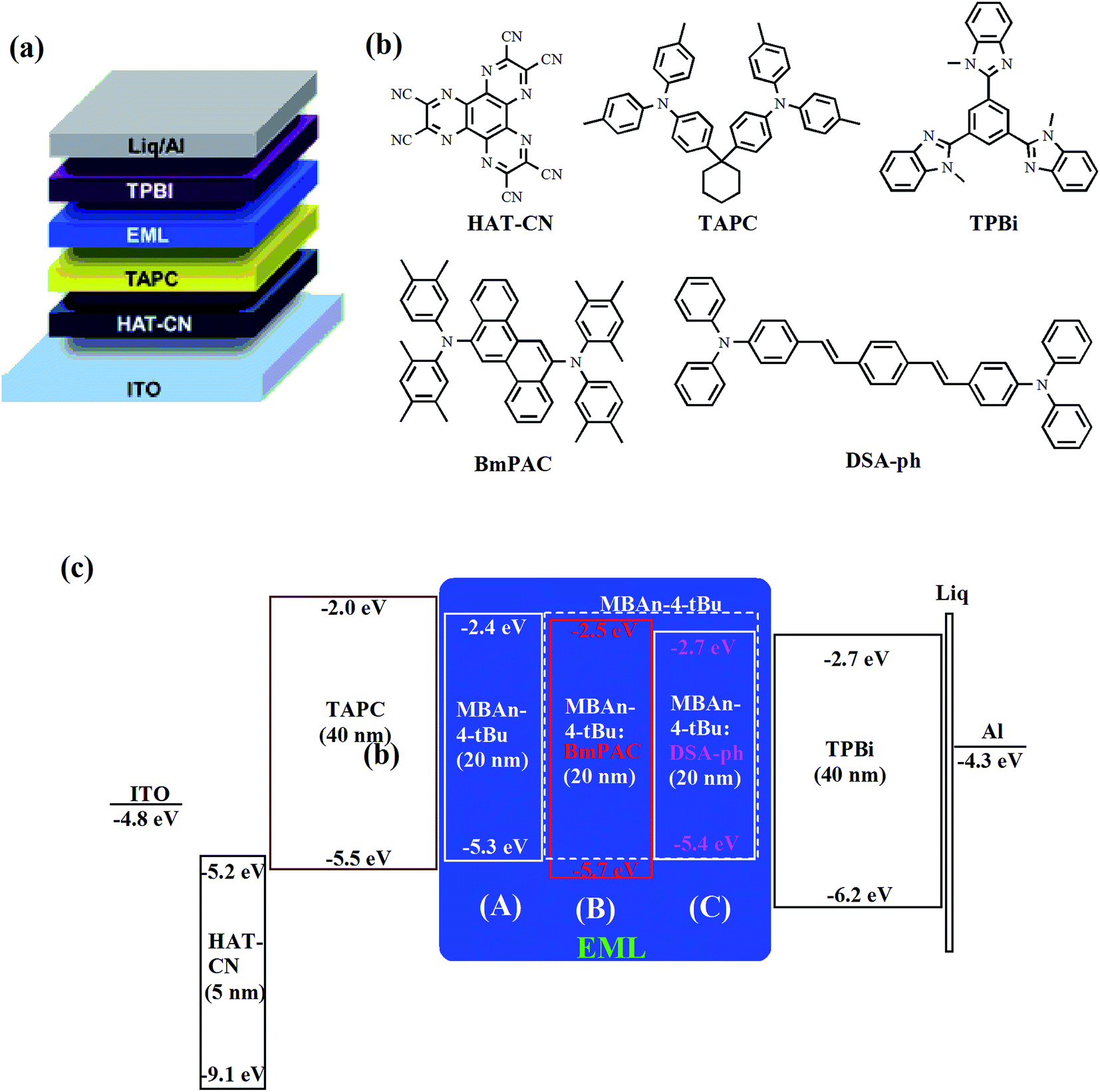
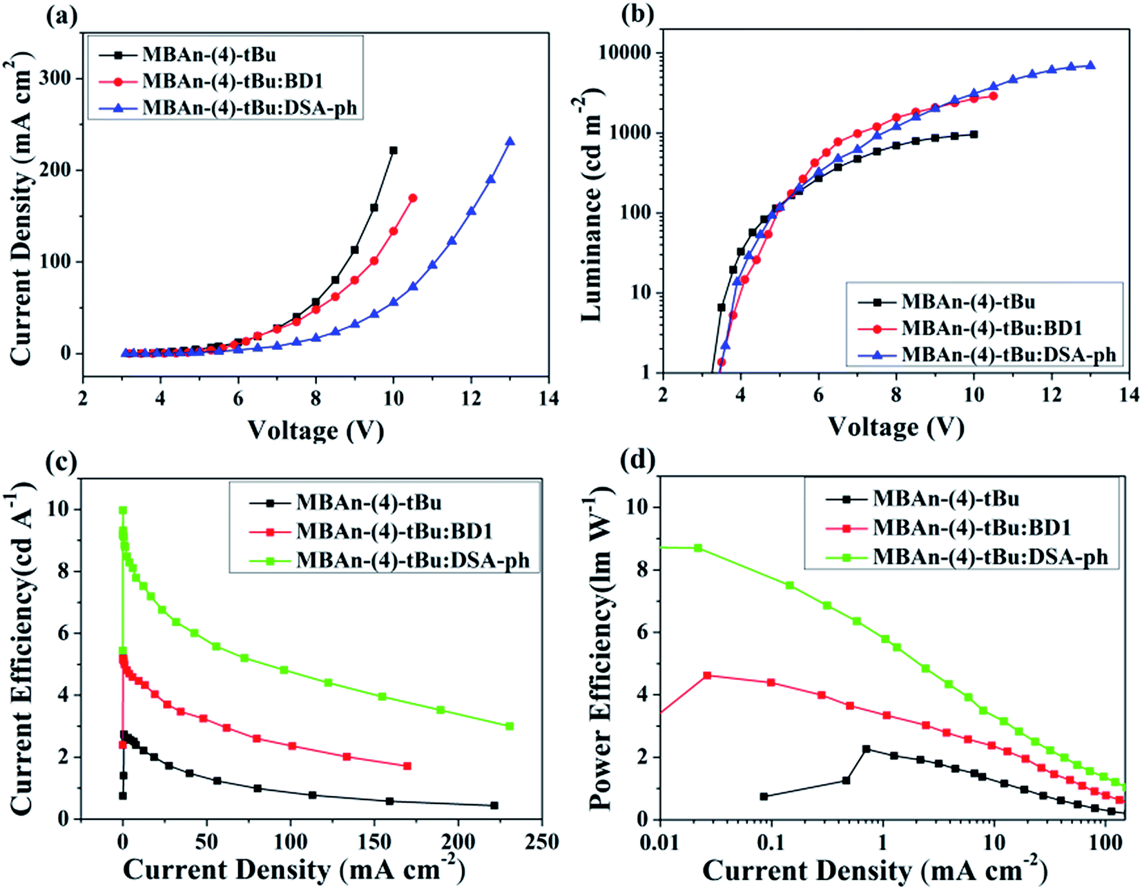
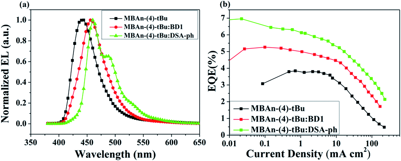
We first characterized the EL performance of MBAn-(4)-tBu as a blue emitter by fabricating a non-doped OLED with the configuration of device A: ITO/HAT-CN (5 nm)/TAPC (40 nm)/MBAn-(4)-tBu (20 nm)/TPBi (40 nm)/Liq (1 nm)/Al (120 nm). HAT-CN was used as a hole injection layer (HIL), TAPC was used as a hole transporting layer (HTL) and TPBi was used as an electron transporting layer (ETL) and exciton blocking layer. Liq and Al served as an electron-injecting layer (EIL) and cathode, respectively. The device structure, molecular structures and energy levels used in the OLEDs are illustrated in Fig. 6. Fig. 7 and 8 show the current density–voltage–luminance–efficiency (J–V–L–η) characteristics of the MBAn-(4)-tBu-based devices. The device performance parameters and EL emission characteristics are summarized in Table 1. To assess the utility of MBAn-(4)-tBu as a blue emitter, we also fabricated a CBP-doped (4,4′-N,N′-dicarbazolyl-1,1′-biphenyl) device, and the dopant was co-evaporated with CBP to give the optimal doping concentration of 5 wt% in the EML. The J–V–L–η characteristics and typical EL spectra of the MBAn-(4)-tBu-doped CBP device are shown in Fig. S3 and S4.†
 |
| | Fig. 6 (a) Device structure, (b) chemical structures of the compounds used in the OLEDs and (c) schematic energy level diagram of the devices. | |
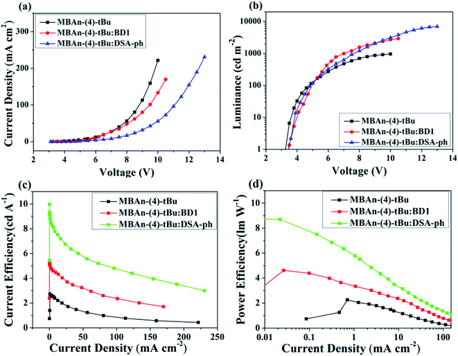 |
| | Fig. 7 (a) Current density–voltage curves, (b) brightness–voltage curves, (c) current efficiency–current density curves and (d) power efficiency–current density curves for the MBAn-(4)-tBu devices. | |
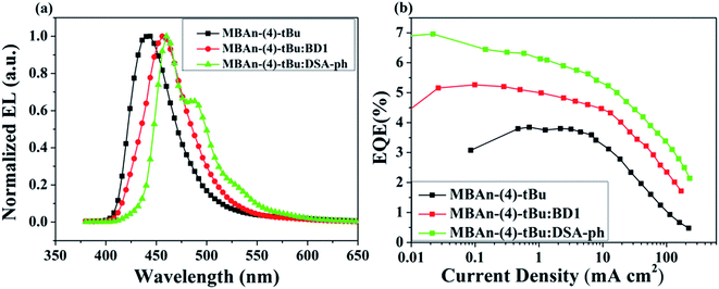 |
| | Fig. 8 (a) Normalized EL spectra of the MBAn-(4)-tBu devices and (b) external quantum efficiency–current density curves for the MBAn-(4)-tBu devices. | |
Table 1 EL performance of the blue OLEDs
| EML |
Vona (V) |
λELb (nm) |
Lmaxc (cd m−2) |
ηcd (cd A−1) |
ηpd (lm W−1) |
ηextd (%) |
FWHWb (nm) |
CIE (x, y)b |
| Turn-on voltage at 1 cd m−2. Values collected at 8 V. Maximum luminance. Values collected at a peak efficiency. |
| MBA-(4)-tBu |
3.2 |
444 |
965 |
2.74 |
2.26 |
3.94 |
49 |
(0.16, 0.07) |
| MBA-(4)-tBu:BD1 |
3.5 |
456 |
2905 |
5.31 |
4.62 |
5.26 |
51 |
(0.14, 0.11) |
| MBA-(4)-tBu:DSA-ph |
3.5 |
460 |
6922 |
9.97 |
8.73 |
6.96 |
53 |
(0.14, 0.18) |
Device A exhibited an emission band maximum at 444 nm, with CIE coordinates of (0.16, 0.07) and a narrow FWHM of 49 nm, and the CIE coordinates are very close to the NTSC standard blue CIE coordinates of (0.14, 0.08). The device had a low turn-on voltage (at a luminance of 1 cd m−2) of 3.2 V owing to the good matching of the HOMO and LUMO energy levels between the hole and electron transporting materials and the emitter. The maximum external quantum (ηext), current (ηC) and power efficiencies (ηP) were 3.94%, 2.74 cd A−1 and 2.26 lm W−1, respectively, which were comparable to those of the state-of-the-art non-doped deep blue OLEDs with CIEy coordinates lower than 0.10.24,32–35 Such high efficiencies may result from the high PLQY and more balanced carrier transport of MBAn-(4)-tBu. The non-doped device A, using MBAn-(4)-tBu as an emitter, exhibits a deep blue emission with CIE coordinates of (0.16, 0.07), while the reported BAn-(4)-tBu device shows pure blue emission characteristics with CIE coordinates of (0.17, 0.16).20 Besides, the MBAn-(4)-tBu device exhibits superior performance to the BAn-(4)-tBu device, with a Von value of 4.4 V, maximum ηext value of 1.12%, ηC value of 1.87 cd A−1 and ηP value of 0.92 lm W−1, due to its conjugated structure. Obviously, the newly synthesized 3,3′-dimethyl-9,9′-bianthracene derivative shows potential for application as a highly efficient deep blue emitter for OLEDs.
Furthermore, doped devices have been fabricated and evaluated using well-known BD1 and DSA-ph as blue fluorescent dopants to study the EL performance of MBAn-(4)-tBu as a host material due to its wide band gap and balanced ambipolar carrier transporting abilities. The configurations of the devices are compared below:
Device B: ITO/HAT-CN (5 nm)/TAPC (40 nm)/MBAn-(4)-tBu: 3% BD1 (20 nm)/TPBi (40 nm)/Liq (1 nm)/Al (120 nm).
Device C: ITO/HAT-CN (5 nm)/TAPC (40 nm)/MBAn-(4)-tBu: 5% DSA-ph (20 nm)/TPBi (40 nm)/Liq (1 nm)/Al (120 nm).
From the J–V–L–η characteristics as shown in Fig. 7 and 8, we note that an excellent performance of pure blue OLEDs can be achieved using MBAn-(4)-tBu as the host. Both of the BD1- and DSA-ph-doped MBAn-(4)-tBu devices display low turn-on voltages of 3.5 V. Device C, using DSA-ph as an emitter, revealed a maximum brightness (Lmax) of 6922 cd m−2 at 13 V (220 mA cm−2) with CIE coordinates of (0.14, 0.18), while device B, using BD1 as an emitter, showed a lower Lmax value of 2905 cd m−2 with CIE coordinates of (0.14, 0.11). It is noteworthy that excellent efficiencies, with a maximum ηC value of 9.97 cd A−1, ηP value of 8.73 lm W−1 and ηext value of 6.96%, were obtained for device C, which were much higher than those for device B (ηC of 5.31 cd A−1, ηP of 4.62 lm W−1 and ηext of 5.26%).
The radiative exciton yield can be calculated according to the following equation:
| ηext = γ × ΦPL × ηr × ηout |
where
γ is the carrier recombination efficiency, which in the ideal case is supposed to be unity if the injected holes and electrons are fully recombined and degrade to excitons in the emissive layer,
ΦPL is the PLQY of the emission layer,
ηr is the radiative exciton yield and
ηout is the light out-coupling efficiency, which is 20% if there are not any out-coupling enhancing structures in the device. For the MBAn-(4)-
tBu
![[thin space (1/6-em)]](https://www.rsc.org/images/entities/char_2009.gif)
:
DSA-ph-doped device, the maximum
ηext value is 6.96%, and the
ΦPL value of the doped film using MBAn-(4)-
tBu as the host with 5% weight ratio of DSA-ph as the dopant is 80%. Thus, the calculated radiative exciton yield is 43.5%, provided that
γ is unity and
ηout is 20%. The estimated radiative exciton yield far exceeds the 25% branching ratio of the singlet exciton yield, and we can come to the conclusion that the MBAn-(4)-
tBu host can significantly enhance the
ηr value in EL devices. Careful analysis indicates that the superior efficiency of the MBAn-(4)-
tBu
:
5% DSA-ph-doped device (
ηext = 6.96%) may be attributed to several possible factors. (1) The host molecule based on the MBAn moiety with a particular twisted intramolecular charge-transfer excited state (TICT-state), which participates in a charge-transfer (CT) intersystem crossing mechanism, realizes transitions from the triplet to singlet CT states.
15 At the dopant site, the available singlet excitons formed
via Förster energy transfer from the host, MBAn-(4)-
tBu, to the dopant are greatly increased. (2) The MBAn-(4)-
tBu host exhibits an ambipolar transporting nature, which is effective for balancing holes and electrons in the emitting layer (EML). (3) The HOMO and LUMO energy of the devices are matched well with those of the neighboring TAPC HTL and TPBi ETL, thus leading to good injection of carrier charges and good confinement of both carriers and excitons. Nevertheless, the EL intensity had a linear relationship with the current density at low current injection, demonstrating that the contribution from triplet–triplet annihilation (TTA) is insignificant.
4. Conclusions
In conclusion, a 3,3′-dimethyl-9,9′-bianthracene derivative (MBAn-(4)-tBu) was designed and synthesized with the aim of developing new deep blue fluorophores, which was modified from non-D–A type BAn-(4)-tBu. The emitting compound exhibited ambipolar transporting characteristics identified by single-carrier devices. MBAn-(4)-tBu can be used as a high-efficiency deep blue emitter with CIE coordinates of (0.16, 0.07), corresponding to a 3.94% EQE in the non-doped blue fluorescent device. In particular, MBAn-(4)-tBu worked as an excellent host material for BD1 and DSA-ph dopants to obtain high-performance OLEDs with excellent EQEs of 5.26% and 6.96%, respectively. Further studies exploring the functionality of the 3,3′-dimethyl-9,9′-bianthracene derivative are underway in our lab.
Conflicts of interest
There are no conflicts to declare.
Acknowledgements
We are grateful for support from the National Natural Scientific Foundation of China (61308093, 61571317, 61274056, 11504257 and 61475109), the New Teachers’ Fund for Doctor Stations (20131402120020), the China Postdoctoral Science Foundation (2015M572454), the Key Research and Development (International Cooperation) Program of Shanxi (201603D421042), and the Platform and Base Special Project of Shanxi (201605D131038).
Notes and references
- C. W. Tang and S. A. VanSlyke, Appl. Phys. Lett., 1987, 51, 913 CrossRef CAS.
- L. S. Hung and C. H. Chen, Mater. Sci. Eng., R, 2002, 39, 143 CrossRef.
- S. R. Forrest, Nature, 2004, 428, 911 CrossRef CAS PubMed.
- Y. Sun, N. C. Giebink, H. Kanno, B. Ma, M. E. Thompson and S. R. Forrest, Nature, 2006, 440, 908 CrossRef CAS PubMed.
- M. Zhu and C. Yang, Chem. Soc. Rev., 2013, 42, 4963 RSC.
- X. Yang, X. Xu and G. Zhou, J. Mater. Chem. C, 2015, 3, 913 RSC.
- J. Ye, Z. Chen, M. K. Fung, C. Zheng, X. Ou, X. Zhang, Y. Yuan and C.-S. Lee, Chem. Mater., 2013, 25, 2630 CrossRef CAS.
- H. Liu, Q. Bai, W. Li, Y. Guo, L. Yao, Y. Gao, J. Li, P. Lu, B. Yang and Y. Ma, RSC Adv., 2016, 6, 70085 RSC.
- S. Zhang, W. Li, L. Yao, Y. Pan, F. Shen, R. Xiao, B. Yang and Y. Ma, Chem. Commun., 2013, 49, 11302 RSC.
- X. Ouyang, X. Zhang and Z. Ge, Dyes Pigm., 2014, 103, 39 CrossRef CAS.
- J. Hu, Y. Pu, F. Satoh, S. Kawata, H. Katagiri, H. Sasabe and J. Kido, Adv. Funct. Mater., 2014, 2, 2064 CrossRef.
- S. Chen, Y. Wu, Y. Zhao and D. Fang, RSC Adv., 2015, 5, 72009 RSC.
- P. Natarajan and M. Schmittel, J. Org. Chem., 2013, 78, 10383 CrossRef CAS PubMed.
- J. Song, S. Park, S. J. Lee, Y. K. Kim and S. S. Yoon, Dyes Pigm., 2015, 114, 40 CrossRef CAS.
- P. Zhang, W. Dou, Z. Ju, L. Yang, X. Tang, W. Liu and Y. Wu, Org. Electron., 2013, 14, 915 CrossRef CAS.
- Y. Yu, Z. Wu, Z. Li, B. Jiao, L. Li, L. Ma, D. Wang, G. Zhou and X. Hou, J. Mater. Chem. C, 2013, 1, 8117 RSC.
- Z. Li, W. Liu, Y. Yu, X. Lv, C. Si, Z. Wu, Y. Cui, H. Jia, F. Shi and Y. Hao, Dyes Pigm., 2015, 122, 238 CrossRef CAS.
- Y. Yu, B. Jiao, Z. Wu, Z. Li, L. Ma, G. Zhou, W. Yu, S. K. So and X. Hou, J. Mater. Chem. C, 2014, 2, 9375 RSC.
- F. Gao, J. Ren, Z. Li, S. Yuan, Z. Wu, Y. Cui, H. Jia, J. Yu, H. Wang, F. Shi and Y. Hao, Opt. Mater. Express, 2015, 5, 2468 CrossRef CAS.
- Z. Li, Y. Sun, H. Li, C. Si, X. Lv, B. Jao, Z. Wu, Y. Cui, J. Yu, H. Wang, F. Shi and Y. Hao, Synth. Met., 2016, 217, 102 CrossRef CAS.
- P. Xue, B. Yao, X. Liu, J. Sun, P. Gong, Z. Zhang, C. Qian, Y. Zhang and R. Lu, J. Mater. Chem. C, 2015, 3, 1018 RSC.
- F. Bell and D. H. Waring, J. Chem. Soc., 1949, 267 RSC.
- U. Müller and M. Baumgarten, J. Am. Chem. Soc., 1995, 117, 5840 CrossRef.
- H. S. Jang, K. H. Lee, S. J. Lee, Y. K. Kim and S. S. Yoon, Mol. Cryst. Liq. Cryst., 2012, 563, 173 CrossRef CAS.
- X. Zhan, N. Sun, Z. Wu, J. Tu, L. Yuan, X. Tang, Y. Xie, Q. Peng, Y. Dong, Q. Li, D. Ma and Z. Li, Chem. Mater., 2015, 27, 1847 CrossRef CAS.
- M. A. Kahlow, T. J. Kang and P. F. Barbara, J. Phys. Chem., 1987, 91, 6452 CrossRef CAS.
- J. Catalan, C. Diaz, V. Lopez, P. Perez and R. M. Claramunt, J. Phys. Chem., 1996, 100, 18392 CrossRef CAS.
- C. W. Tang, S. A. VanSlyke and C. H. Chen, J. Appl. Phys., 1989, 65, 3610 CrossRef CAS.
- M. T. Li, W. L. Li, W. M. Su, F. X. Zang, B. Chu, Q. Xin, D. Bi, B. Li and T. Yu, Solid-State Electron., 2008, 52, 121 CrossRef CAS.
- S. Takizawa, V. A. Montes and P. Anzenbacher, Chem. Mater., 2009, 21, 2452 CrossRef CAS.
- K. Wang, S. P. Wang, J. B. Wei, Y. Miao, Y. Liu and Y. Wang, Org. Electron., 2014, 15, 3211 CrossRef CAS.
- S. Kumar and D. Kumar, J. Mater. Chem. C, 2016, 4, 193 RSC.
- S. Fan, J. You, Y. Miao, H. Wang, Q. Bai, X. Liu, X. Li and S. Wang, Dyes Pigm., 2016, 129, 34 CrossRef CAS.
- D. Yu, F. Zhao, Z. Zhang, C. Han, H. Xu, J. Li, D. Ma and P. Yan, Chem. Commun., 2012, 48, 6157 RSC.
- C. Han, F. Zhao, Z. Zhang, L. Zhu, H. Xu, J. Li, D. Ma and P. Yan, Chem. Mater., 2013, 25, 4966 CrossRef CAS.
Footnote |
| † Electronic supplementary information (ESI) available. See DOI: 10.1039/c7ra09179f |
|
| This journal is © The Royal Society of Chemistry 2017 |
Click here to see how this site uses Cookies. View our privacy policy here. 
 Open Access Article
 This Open Access Article is licensed under a
  *a,
Xiangkun Wanga,
Xiang Lva,
Changfeng Sib,
Bin Wei*b,
Hua Wangc and
Yuying Hao*a
*a,
Xiangkun Wanga,
Xiang Lva,
Changfeng Sib,
Bin Wei*b,
Hua Wangc and
Yuying Hao*a