
 Open Access Article
 This Open Access Article is licensed under a
 Creative Commons Attribution 3.0 Unported Licence
Reply to the ‘Comment on “Microwave synthesis of graphene/magnetite composite electrode material for symmetric supercapacitor with superior rate performance”’ by Rajaperumal M., RSC Adv., 2017, 7, DOI: 10.1039/c7ra04129b
Kaliyappan Karthikeyana,
Dharmalingam Kalpana*b,
Samuthirapandian Amaresha and
Yun Sung Lee*a
aFaculty of Applied Chemical Engineering, Chonnam National University, Gwang-ju 500-757, South Korea. E-mail: leeys@chonnam.ac.kr
bCentral Electrochemical Research Institute, Karaikudi 630006, India. E-mail: drkalpanaa@gmail.com; Tel: +04565-241412
First published on 8th November 2017
First of all, this work was completed at the Chonnam National University, Korea by the first author of this paper Mr Karthikeyan.(1) The main scope of our work is to facilitate the synthesis of Fe3O4–graphene (Fe–GNS) nanoparticles using a simple and green synthesis method and to study the effect of the preparation technique on their capacitive performance. Since the preparation conditions affect the electrochemical performance of any cathode materials (Fe3O4-conductive carbon composites have already been prepared using various methods), a novel microwave method was adopted to fabricate the Fe–GNS composites and their application as capacitors studied. In our work, we have achieved excellent capacitive performance of the Fe–GNS system, which was attributed to its morphological features (explained well in the manuscript itself).
(2) Regarding the weight, the weight of the active material in the electrode was 0.3125 mg. The weight difference was about 0.4 mg and the active material in the electrode was about 0.3125 (∼79 wt%).
(3) With reference to the article published in J. Mater. Chem., 2011, 21, 3422–3427, they have achieved 480 F g−1 at 5 A g−1 as shown in Fig. 3b. As you can see from Fig. 3b, the discharge time could be ∼43 s, voltage is 1 V and current is 5 A g−1 and the authors reported the capacitance of 480 F g−1.
(4) About your question on capacitive performance, the rate performance of the Fe–GNS was resulted from its morphological feature as explained well in the paper. Since the open system formed during the synthesis of Fe–GNS can accommodate more electrolyte within the composite structure, providing a flexible structure against inherent mechanical stresses formed during the charge discharge at high current rates, which tremendously improved the rate performance in the present case. Also resulted from its improved electrical conductivity, which is higher than the one reported in J. Mater. Chem., 2011, 21, 3422–3427. Furthermore, the impedance curves in Fig. 6, did not show typical capacitance behavior (inclined line at low frequency region should be close to 45 degree, which is typical capacitive behavior). But, Fig. 6 in JMC paper did not show such behavior and it still curved, indicating there was more charge transfer resistance. But, in our case, the electrode showed perfect capacitance behavior at low frequency region, indicating better capacitive behavior, which was confirmed in cycling test. Again, it is well known that the composite materials with improved electrical conductivity would have exhibited enhanced electrochemical performance along with prolonged cycle life.
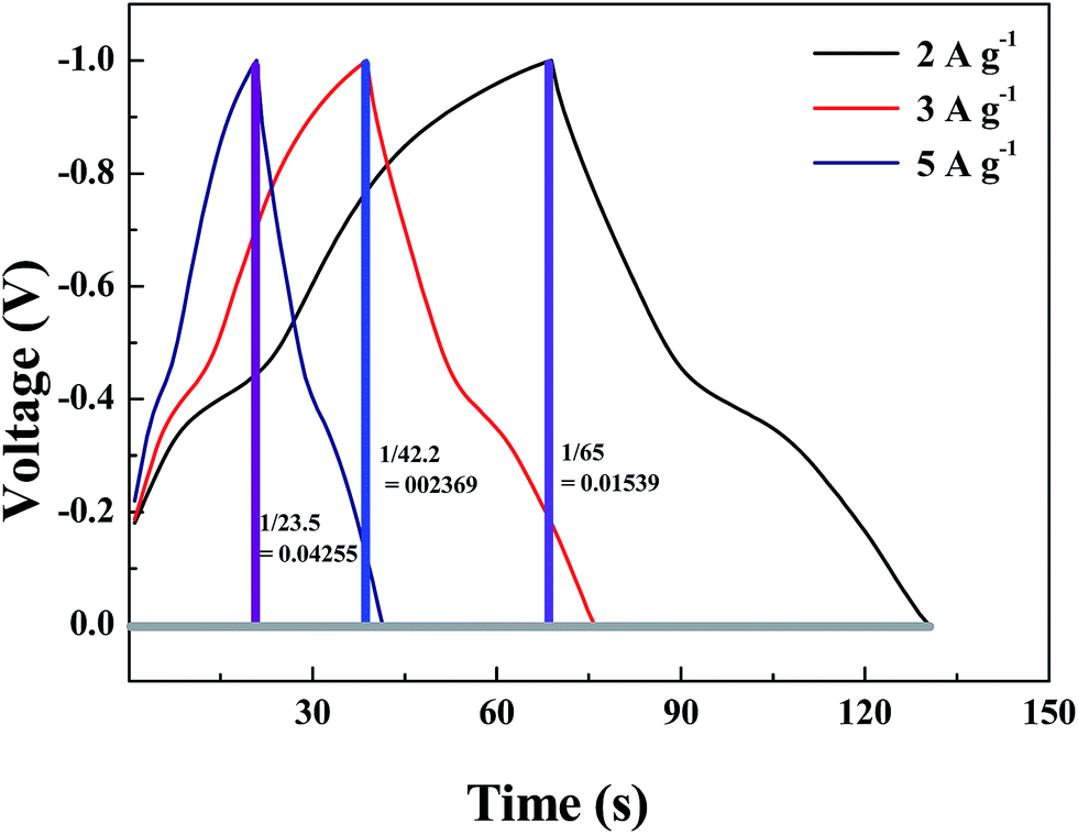 | ||
| Fig. 1 Calculation of dV/dt from the discharge curve. The whole part has been considered for the calculation. | ||
Specific capacitance per unit mass of single electrode can be calculated using the following formula:
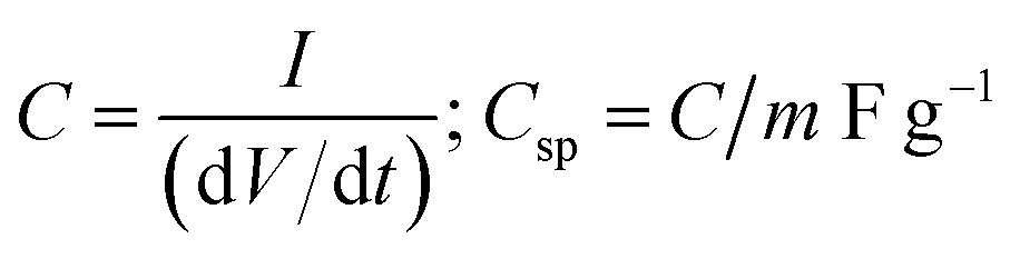
For Fe3O4–GNS electrode – I = 2 mA, m = 0.3125 mg
| C = 2 × 10⁻³/0.01539 = 129.95 × 10⁻³ F |
| Csp = (129.95 × 10⁻³/0.3125 × 10−3) = 415.84 F g−1 |
Based on this method, the specific capacitance of the single electrodes was calculated at different current densities as follows.
For I = 3 mA, m = 0.3125 mg
| C = 3 × 10⁻³/0.02369 = 126.64 × 10⁻³ F |
| Csp = (126.64 × 10⁻³/0.3125 × 10−3) = 405.248 F g−1 |
For I = 5 mA, m = 0.3125 mg
| C = 5 × 10⁻³/0.04255 = 117.508 × 10⁻³ F |
| Csp = (117.50 × 10⁻³/0.3125 × 10−3) = 376 F g−1 |
The same method was used to calculate the capacitance value for pristine Fe3O4–GNS electrode also.
Conflicts of interest
There are no conflicts to declare.References
- M. Guo, J. Balamurugan, X. Li, N. H. Kim and J. H. Lee, Hierarchical 3D Cobalt-Doped Fe3O4 Nanospheres@NG Hybrid as an Advanced Anode Material for High-Performance Asymmetric Supercapacitors, Small, 2017, 13, 1701275 CrossRef PubMed.
- M. Guo, J. Balamurugan, T. D. Tran, N. H. Kima and J. H. Leea, Facile fabrication of Co2CuS4 nanoparticle anchored N-doped graphene for high-performance asymmetric supercapacitors, J. Mater. Chem. A, 2016, 1–3 Search PubMed.
| This journal is © The Royal Society of Chemistry 2017 |