 Open Access Article
Creative Commons Attribution 3.0 Unported Licence
Li4Ti5O12 nanosquares@ultrathin carbon nanofilms on a large scale with enhanced properties in lithium-ion batteries†
Yonglian Xiong *,
Yuwei Chen,
Jun Yan,
Quanhui Hou and
Wei Liu
College of Automotive Engineering, Yancheng Institute of Technology, Yancheng, Jiangsu 224051, China. E-mail: serena77@126.com
First published on 17th October 2017
Abstract
In this paper, functionalized carbon-anchored Li4Ti5O12 (C-LTO) ultrathin nanosquares were synthesized via a combination of ball milling and solid state routes in a large scale. The resulting products were investigated by instrumental analyses such as XRD, SEM, HRTEM and IR. It was found that the transformation from microspheres to nanosquares was readily achieved through a “mechanical activation and Ostwald ripening” mechanism via examining the intermediate product structure at different reaction stages. This research indicates that C-LTO nanosquares with high crystallinity are a promising anode material for high-specific-energy in rechargeable lithium batteries.
I. Introduction
Ultrathin two-dimensional (2D) layered materials applied in lithium-ion batteries have received considerable attention in recent years, not only because of the peculiar and fascinating properties associated with the remarkable surface-to-volume ratio but also attributed to their unique structures they can satisfy the applications for energy storage and conversion.1,2 For the anode materials in lithium ion batteries, Li4Ti5O12 (LTO) with a spinel structure has been demonstrated as a promising alternative material due to the zero strain characteristic during Li insertion/extraction and high flat potential of about 1.55 V (vs. Li+/Li).3–7 Nevertheless, the poor rate performance of the pristine LTO was seriously affected by sluggish kinetics of lithium electronic conductivity. Hopeful strategies for solving this problem mainly focus on adding conductive carbon, doping metallic cation or developing nanoscaled particles.8–24 However, so far, less attention has been paid to the formation of 2D LTO nanosheets in a large scale. Especially, the controlled synthesis of carbon-anchored Li4Ti5O12 ultrathin nanosquares is insufficient. The major scientific challenges are the effective control of thermodynamics and kinetics for ultrathin Li4Ti5O12 nanosheets, and then uniform anchoring of carbon on the Li4Ti5O12 surface. To excellently solve these issues, the solid-state synthesis is a good choice due to the relatively simple synthesis conditions and low synthesis cost.Herein, we report a simple ball milling and solid state process for the preparation of C-LTO ultrathin nanosquares with a highly crystalline by using anatase TiO2 as the titanium source, Li2CO3 as the lithium source, and glucose solution as the carbon source. Then, a novel formation mechanism of C-LTO ultrathin nanosquares is proposed by systematically to reveal the relationship between vital reaction conditions and prevailing morphology. The C-LTO ultrathin nanosquares in commercial 18![[thin space (1/6-em)]](https://www.rsc.org/images/entities/char_2009.gif) 650 cells are opening a reasonable and promising way in boosting the electrochemical performance for lithium-ion batteries.
650 cells are opening a reasonable and promising way in boosting the electrochemical performance for lithium-ion batteries.
II. Experimental section
A. Sample preparation
Products of Li4Ti5O12 (LTO) nanosquares were successfully synthesized via a simple and low cost solid-state method using anatase phase TiO2 powder (99.99% purity, Hangzhou Wanjing materials co., LTD., Hangzhou China), and Li2CO3 reagent (99.99% purity, Tianqiliye co., LTD., Sichuan, China). Briefly, the chemical reaction can be described as follows:In a typical fabrication of Li4Ti5O12 nanosquares, 1510.3116 g of Li2CO3 and 4000 g of TiO2 (molar ratio of 4![[thin space (1/6-em)]](https://www.rsc.org/images/entities/char_2009.gif) :
:![[thin space (1/6-em)]](https://www.rsc.org/images/entities/char_2009.gif) 5) were thoroughly mixed with the ethyl alcohol as milling medium and stirred at room temperature for 3 h, and then milled in a planetary ball mill for 90 min at a speed of 400 rpm to prepare the uniform precursors. Specially, 2.2 wt% excess Li2CO3 was increased to offset the loss of Li during the whole reaction.25 Following the ball-milling procedure, the these precursors were dried at 100 °C for 4 h in air environment to evaporated the alcohol medium, and the as-fabricated powders were subsequently milled in an agate mortar for 1 h. Afterwards, the fine mixtures were calcined at 750 °C by 6 h with a constant heating rate of 5 °C min−1 to obtain the Li4Ti5O12 nano-samples. After naturally cooled to the ambient temperature, glucose (660.5700 g) was dissolved into 5240 g of ethyl alcohol, and 4000.0000 g of LTO powders were slowly added to the above glucose solution under a strong stirring process. Next, all of the wet materials were half-dried at 60 °C for 24 h, and then sintered at 800 °C for 6 h under high-pure nitrogen atmosphere (99.999%, Air Products and Chemicals, Inc., Tianjin, China) with a heating rate of 5 °C min−1.
5) were thoroughly mixed with the ethyl alcohol as milling medium and stirred at room temperature for 3 h, and then milled in a planetary ball mill for 90 min at a speed of 400 rpm to prepare the uniform precursors. Specially, 2.2 wt% excess Li2CO3 was increased to offset the loss of Li during the whole reaction.25 Following the ball-milling procedure, the these precursors were dried at 100 °C for 4 h in air environment to evaporated the alcohol medium, and the as-fabricated powders were subsequently milled in an agate mortar for 1 h. Afterwards, the fine mixtures were calcined at 750 °C by 6 h with a constant heating rate of 5 °C min−1 to obtain the Li4Ti5O12 nano-samples. After naturally cooled to the ambient temperature, glucose (660.5700 g) was dissolved into 5240 g of ethyl alcohol, and 4000.0000 g of LTO powders were slowly added to the above glucose solution under a strong stirring process. Next, all of the wet materials were half-dried at 60 °C for 24 h, and then sintered at 800 °C for 6 h under high-pure nitrogen atmosphere (99.999%, Air Products and Chemicals, Inc., Tianjin, China) with a heating rate of 5 °C min−1.
B. Characterization
Chemical compositions and crystalline structures of the resulting LTO products were investigated by using a Rigaku D/max2500PC X-ray diffraction (XRD) with Cu-Kα radiation (λ = 1.54056 Å). The surface morphologies of the samples were performed on a field-emission scanning electron microscopy (JSM-6360LV, Japan Electronics Co., Ltd Tokyo, Japan) and a high resolution transmission electron microscopy (HRTEM, FEI Tecnai G2 F20 S-TWIN TMP with an acceleration voltage of 40–200 kV). The carbon content of C-LTO nanosquare sample was measured by TG method (Netzsch STA 449C).C. Electrochemical measurement
The first discharge–charge curves and rate capacities of the pure LTO and C-LTO sample assembled in CR2430 coin cell were tested in the range of 1–3 V. The more electrochemical performances of C-LTO sample were measured in the 18![[thin space (1/6-em)]](https://www.rsc.org/images/entities/char_2009.gif) 650 cells which were designed as power battery. The anode electrode was assembled by the mixture of Li4Ti5O12 nanosquares: carbon black: polyvinylidene fluoride (PVDF) with a weight ratio of 92
650 cells which were designed as power battery. The anode electrode was assembled by the mixture of Li4Ti5O12 nanosquares: carbon black: polyvinylidene fluoride (PVDF) with a weight ratio of 92![[thin space (1/6-em)]](https://www.rsc.org/images/entities/char_2009.gif) :
:![[thin space (1/6-em)]](https://www.rsc.org/images/entities/char_2009.gif) 4
4![[thin space (1/6-em)]](https://www.rsc.org/images/entities/char_2009.gif) :
:![[thin space (1/6-em)]](https://www.rsc.org/images/entities/char_2009.gif) 4. The cathode electrode was assembled by 90% LiMn2O4 (LMO) with 6% carbon fiber and 4% binder PVDF. 1.1 M LiPF6 was dissolved in a 40
4. The cathode electrode was assembled by 90% LiMn2O4 (LMO) with 6% carbon fiber and 4% binder PVDF. 1.1 M LiPF6 was dissolved in a 40![[thin space (1/6-em)]](https://www.rsc.org/images/entities/char_2009.gif) :
:![[thin space (1/6-em)]](https://www.rsc.org/images/entities/char_2009.gif) 30
30![[thin space (1/6-em)]](https://www.rsc.org/images/entities/char_2009.gif) :
:![[thin space (1/6-em)]](https://www.rsc.org/images/entities/char_2009.gif) 30 vol% mixture of dimethyl carbonate (DMC), diethylene carbonate (DEC) and ethylene carbonate (EC) as electrolyte and Celgard®PP/PE/PP (20 μm) as separator. The rate discharge performance of full battery was tested over the voltage of 1.2 to 3.0 V on an Arbin Battery Test Equipment (Arbin (60 A/5 V), America). If without any special explaining, the other testing voltage is the range of 1.5–3.0 V in full battery.
30 vol% mixture of dimethyl carbonate (DMC), diethylene carbonate (DEC) and ethylene carbonate (EC) as electrolyte and Celgard®PP/PE/PP (20 μm) as separator. The rate discharge performance of full battery was tested over the voltage of 1.2 to 3.0 V on an Arbin Battery Test Equipment (Arbin (60 A/5 V), America). If without any special explaining, the other testing voltage is the range of 1.5–3.0 V in full battery.
III. Results and discussion
A. Characterization of the as-obtained C-Li4Ti5O12
The crystal phase of the C-LTO samples prepared in these experiments was characterized with the XRD measurement. Fig. 1 shows the representative XRD pattern of the as-synthesized product, and all the Bragg reflection peaks can be readily indexed to the cubic phase of Li4Ti5O12. The lattice constants of LTO can be assigned to be a = 8.358(8) Å, which match well with the standard values [space group: Fd![[3 with combining macron]](https://www.rsc.org/images/entities/char_0033_0304.gif) m (no. 227), ICDD-JCPDS card no. 49-0207]. The phase of the final products was expectantly crystallographic in nature because the preparation was achieved at an adequately high temperature. The diffraction peaks from the carbon phase was very weak for the ultrathin amorphous nanofilm on the outside of nanosquares, which can be proved by the following investigation by HRTEM technology. No signals from other impurity phases such as TiO2 and Li2CO3 were observed. After heating at 800 °C for 6 h, the crystallinity of Li4Ti5O12 nanosquares became remarkable as evidenced by the sharp and strong peaks, particularly the (111), (311) and (400) peaks from the cubic Li4Ti5O12.26
m (no. 227), ICDD-JCPDS card no. 49-0207]. The phase of the final products was expectantly crystallographic in nature because the preparation was achieved at an adequately high temperature. The diffraction peaks from the carbon phase was very weak for the ultrathin amorphous nanofilm on the outside of nanosquares, which can be proved by the following investigation by HRTEM technology. No signals from other impurity phases such as TiO2 and Li2CO3 were observed. After heating at 800 °C for 6 h, the crystallinity of Li4Ti5O12 nanosquares became remarkable as evidenced by the sharp and strong peaks, particularly the (111), (311) and (400) peaks from the cubic Li4Ti5O12.26
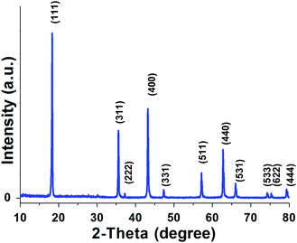 | ||
Fig. 1 Structural characterization of Li4Ti5O12 nanosquares material for lithium-ion batteries in 18![[thin space (1/6-em)]](https://www.rsc.org/images/entities/char_2009.gif) 650 cells. 650 cells. | ||
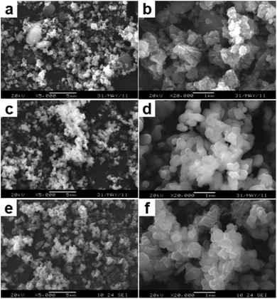
To monitor the formation mechanism of these Li4Ti5O12 nanocrystals, a series of shape-controlled experiments were performed by examining the intermediate products structure at different reaction stages. Fig. 2 shows the SEM images of the samples taken from the reactants at different growth durations. These images definitely indicated the conversion process from nanoparticles to nanosheets and then to ultrathin square-like architectures. Fig. 2a displayed the SEM image of the products synthesized after ball mill for 90 min. It was observed that the initial stage products were made of numerous microspheres with the diameter of 200–400 nm. These microspheres was assembled by a great number of nanoparticles with a diameter of 10–20 nm, as shown in the high-magnification SEM image in Fig. 2b. After thermal treatment at 750 °C for 6 h, nanosheets with the thickness of about 60 nm and the length of 250–400 nm appear instead of nanoparticles (Fig. 2c and d). And this phenomenon powerful related to the high reaction rate caused by the enhanced of reaction temperature. It is worth noting that anchoring of carbon on the LTO surface is achieved, when the LTO powders were added to the glucose solution and continuously sintered at 800 °C for 6 h (Fig. 2e). The high-resolution image shown in Fig. 2f illustrated that the samples were composed of ultrathin nanosquares coating carbon without other aggregates. Compared with the product obtained after calcined at 750 °C for 6 h (Fig. 2c and d), the nanosquare lengths remained constant (250–400 nm), but the thickness dramatically decreased to about 25 nm, which may be the result of an Ostwald process.27 In addition, the surface of these nanosquares is relatively smooth due to the high surface energy. It was deeply believed that the reaction temperature significantly influence the nucleation rate and morphology of the final nanocrystals, and higher sintered temperatures fit for the growth of single-crystal nanostructures.
For the formation of these inorganic square-like structures, here, a novel growth mechanism model has been put forward. In the first step, through the mechanical activation, nanoparticles easily appear in the ball grinder after intensive milling for 90 min, and these nanoparticles may serve as the primary particles for the formation of nanosquares. During the nanostructures annealing at 750 °C, the nanoparticles spontaneous self-organization and transformed to uniform LTO nanosheets. In the following experiment stage, owing to the “Ostwald ripening process”, C-LTO ultrathin nanosquares formed at 800 °C.
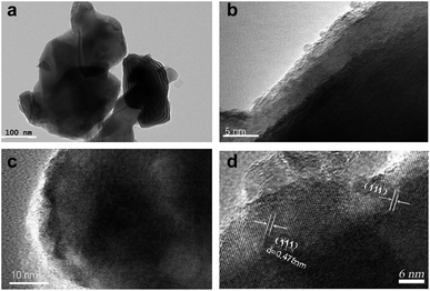
The thickness of carbon film and the high crystallinity of C-LTO nanosquares, which is fabricated at 800 °C, is further analyzed by HRTEM measurements. The high crystallinity and carbon film was confirmed in Fig. 3(c and d). The HRTEM images in Fig. 3(a and b) reveal well-defined nanosquares and carbon coating surface. Carbon coating layer about 5–10 nm in size was easily observed on the outer surface of nanosquares, which is in agreement with IR spectra in Fig. S1.† As shown, two absorption peaks at 657.8 cm−1 and 467.3 cm−1 can be clearly seen. These two bands are due to the symmetric and asymmetric stretching vibrations of the octahedral groups TiO6 lattice, respectively.28 The multi-absorption peaks at 700–1700 cm−1 range are due to the flexural vibrations of C–O band, which confirmed the existence of carbon in the composite.
A curve of weight loss as a function of temperature for pure LTO sample and C-LTO samples by TG method is presented in Fig. S2.† The greatest weight loss for the samples both occurred in a temperature range of 400–600 °C. The content of carbon in the composite C-LTO sample at 800 °C is 4.29%. And the weight loss of pure LTO sample for comparison is 0.48%.
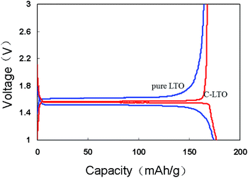
Fig. 4 displays the first discharge/charge curves of pure LTO and C-LTO samples in coin-type cell at current rate of 0.05C over the range of 1–3 V. The curves present very flat plateaus at the potential of around 1.55 V (vs. Li+/Li), which is ascribed to a two-phase reaction.29 A single-phase region with a sharp potential drop from 3 to 1.55 V and 1.55 to 1 V was found. The first efficiency is up to 94.7% which discharge and charge capacity of C-LTO sample is 177.2 mA h g−1 and 167.8 mA h g−1, respectively. And the first efficiency is 94.3% of pure LTO for comparison and near to C-LTO sample. But the polarization between the discharge and charge plateau is 102 mV for pure LTO and only 28.6 mV for C-LTO, indicating that the kinetics of the pure LTO sample are indeed improved after carbon coating.
Furthermore, the rate performance of C-LTO sample and pure LTO sample for comparison in coin cell is shown in Fig. S3.† At current rates of 5C and 10C, the discharge capacities of C-LTO sample are 147 and 136 mA h g−1, respectively, which are higher than those of the pure sample (101 and 48 mA h g−1). It is further confirmed the advantage of the use of carbon as a coating layer for LTO material.
To further investigate on the C-LTO nanosquares electrochemical performance which is manufactured in the large scale, the power battery was designed using 18![[thin space (1/6-em)]](https://www.rsc.org/images/entities/char_2009.gif) 650-type battery. The basic data including capacity, internal resistance (IR) and coulombic efficiency of 18
650-type battery. The basic data including capacity, internal resistance (IR) and coulombic efficiency of 18![[thin space (1/6-em)]](https://www.rsc.org/images/entities/char_2009.gif) 650-type cells (DA for cell number) is shown in Fig. S4.† The capacity and IR is about 1090 mA h and 13.5 mΩ. The average efficiency is ∼92% (from 91.5–93.7%). The volume energy density of the cell is about to 168 w L−1.
650-type cells (DA for cell number) is shown in Fig. S4.† The capacity and IR is about 1090 mA h and 13.5 mΩ. The average efficiency is ∼92% (from 91.5–93.7%). The volume energy density of the cell is about to 168 w L−1.
The discharge capacities of the cells at the different discharge rates are listed in Table S1.† The discharge capacity of DA10 is 1054 mA h and 1023 mA h at 20C and 30C, which is the 96.9% and 94.0% of 0.5C capacity, respectively. It shows excellent large current discharge performance which is due to the nanosquares and carbon coating layer. The discharge voltage profiles vs. capacity are demonstrated in Fig. 5. It is observed that at very low current densities, such as 0.5C to 1C, the voltage profiles coincide almost completely. The voltage profile declines obviously when the rate increases to 30C, which can be ascribed to the high polarization from the fast extraction and insertion of lithium ions.
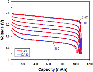 | ||
Fig. 5 Rate discharge performance of 18![[thin space (1/6-em)]](https://www.rsc.org/images/entities/char_2009.gif) 650-type cells with C-LTO nanosquares between 3 and 1.2 V, charging to 3 V with 1C with 60 mA cutoff and rest 15 min, and discharging to 1.2 V. 650-type cells with C-LTO nanosquares between 3 and 1.2 V, charging to 3 V with 1C with 60 mA cutoff and rest 15 min, and discharging to 1.2 V. | ||
Furthermore, the cells with C-LTO nanosquares are performed excellent ultra-low temperature charge and discharge performance. As known, the higher the constant-current charge capacity is, the better the fast charge performance will be. It is shown the constant-current charge capacity is up to 72.5% at −40 °C with 1C current charging in Fig. 6, indicating the good charge performance at ultra-low temperature. Conversely, the batteries with graphite anode are normally not allowed to be charged under −10 °C (otherwise it exists the risk of lithium deposition). Furthermore, the discharged performance with 6C at −40 °C is shown in Fig. S5.† Due to high polarization the voltage curve reduces steeply firstly, then rapidly rise ascribing the heat release and the discharging time continues 555 S. The discharged capacity of 92.5% is achieved. The excellent charge and discharge performance at ultra low temperature will be helpful to enlarge its application field.30
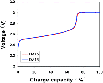 | ||
| Fig. 6 Ultra-low temperature charge performance at −40 °C, charging to 3 V with 1C with 60 mA cutoff. | ||
The cycle performance is shown in Fig. S6† at high rate of 5C. The reversible capacity of the two cells after 1000 cycles, are well maintained 1022, 1050 mA h, respectively. The cycle capacity retention of 95.72% and 96.58% are achieved that the capacity loss is less than 4.5%. This excellent cycle performance could result from the surface modification by carbon and nanosquares.
IV. Conclusions
In summary, unique 2D ultrathin C-LTO nanosheets with highly single-crystalline nature were successfully synthesized on a large scale via a ball milling and calcination process. Initially, a stoichiometric mixture of TiO2 and Li2CO3 was milled and calcined at 750 °C to obtain Li4Ti5O12. Secondly, after adding glucose solution, the mixture was further intensively milled by a planetary ball mill and sintered at 800 °C to prepare carbon-anchored Li4Ti5O12 ultrathin nanosquares. Furthermore, the mechanism of “mechanical activation” following the “Ostwald ripening” process is reasonable to explain the growth of 2D C-LTO ultrathin nanosheets. The investigation on the carbon-anchored Li4Ti5O12 ultrathin nanosquares expands a new way for the controlled size and morphologies preparation, and can promote their advanced application in lithium-ion batteries and supercapacitor. The batteries with C-LTO nanosquares have shown excellent electrochemical properties, especially rate discharge/charge at low temperature performance and large current cycle performance.Conflicts of interest
There are no conflicts of interest to declare.Acknowledgements
This work was supported by funding from the Natural Science Foundation of Jiangsu Province (BK20150425) and National Natural Science Foundation of China (51405419). All authors were involved in carefully revising this paper.References
- C. L. Tan, X. H. Cao, X. J. Wu, Q. Y. He, J. Yang, X. Zhang, J. Z. Chen, W. Zhao, S. k. Han, G. H. Nam, M. Sindoro and H. Zhang, Chem. Rev., 2017, 117, 6225–6331 CrossRef CAS PubMed.
- C. S. Li, Y. Sun, W. H. Lai, J. Z. Wang and S. L. Chou, ACS Appl. Mater. Interfaces, 2016, 8, 27710–27719 CAS.
- K. Ariyoshi, R. Yamato and T. Ohzuku, Electrochim. Acta, 2005, 51, 1125–1130 CrossRef CAS.
- C. Y. Ouyang, Z. Y. Zhong and M. S. Lei, Electrochem. Commun., 2007, 9, 1107–1111 CrossRef CAS.
- N. Zhao, R. Ran, M. L. Liu and Z. P. Shao, Mater. Sci. Eng., R, 2015, 98, 1–71 CrossRef.
- H. G. Jung, S. T. Myung, C. S. Yoon, S. B. Son, K. Amine and B. Scrosati, Energy Environ. Sci., 2011, 4, 1345–1351 CAS.
- S. Chauque, F. Y. Oliva, A. Visintin, D. Barraco, E. P. M. Leiva and O. R. Cámara, J. Electroanal. Chem., 2017, 799, 142–155 CrossRef CAS.
- Y. R. Jhan and J. G. Duh, Electrochim. Acta, 2012, 63, 9–15 CrossRef CAS.
- H. Q. Tang, L. X. Zan and W. F. Mao, J. Electroanal. Chem., 2015, 751, 57–64 CrossRef CAS.
- D. Wang, Z. Huang and X. Y. Wu, Chin. J. Power Sources, 2015, 9, 1826–1827 Search PubMed.
- Q. Y. Zhang, Y. Liu and H. S. Lu, Electrochim. Acta, 2016, 189, 147–157 CrossRef CAS.
- G. N. Zhu, Y. G. Wang and Y. Y. Xia, Energy Environ. Sci., 2012, 5, 6652–6667 CAS.
- J. Shi, Y. H. Liang and L. L. Li, Electrochim. Acta, 2015, 155, 125–131 CrossRef CAS.
- Y. Wang, H. Li and P. He, Nanoscale, 2010, 2, 1294–1305 RSC.
- L. Yu, B. H. Wu and X. W. Lou, Adv. Mater., 2013, 25, 2296–2300 CrossRef CAS PubMed.
- N. D. He, B. S. Wang and J. J. Huang, J. Solid State Electrochem., 2010, 14, 1241–1246 CrossRef CAS.
- Q. Zhou, L. Liu and H. P. Guo, Electrochim. Acta, 2015, 151, 502–509 CrossRef CAS.
- Y. F. Tang, L. Yang, S. F. Huang and Z. Qiu, J. Mater. Chem., 2009, 19, 5980–5984 RSC.
- H. Q. Tang, L. X. Zan, W. F. Mao and Z. Y. Tang, J. Electroanal. Chem., 2015, 751, 57–64 CrossRef CAS.
- C. C. Zhang, D. Shao, J. F. Yu, L. Z. Zhang, X. Y. Huang, D. H. Xu and X. Y. Yu, J. Electroanal. Chem., 2016, 776, 188–192 CrossRef CAS.
- Z. Zhao, Y. L. Xu, M. D. Ji and H. Zhang, Electrochim. Acta, 2013, 109, 645–650 CrossRef CAS.
- J. Q. Wang, Z. Z. Yang, W. H. Li and G. Lin, J. Power Sources, 2014, 266, 323–331 CrossRef CAS.
- Z. L. Wu, G. B. Xu, X. L. Wei and L. W. Yang, Electrochim. Acta, 2016, 207, 275–283 CrossRef CAS.
- K. S. Park, A. Benayad, D. J. Kang and S. G. Doo, J. Am. Chem. Soc., 2008, 130, 14930–14931 CrossRef CAS PubMed.
- Y. J. Gu, Z. Guo and H. Q. Liu, Electrochim. Acta, 2014, 123, 576–581 CrossRef CAS.
- D. Tsubone, T. Hashimoto, K. Igarashi and T. Shimizu, J. Ceram. Soc. Jpn., 1994, 102, 180–184 CrossRef CAS.
- P. W. Voorhees, J. Stat. Phys., 1985, 38, 231–252 CrossRef.
- G. C. Allen and M. Paul, Spectroscopy, 1995, 49, 451 CrossRef CAS.
- S. Scharner, W. Weppner and P. Schmid-Beurmann, J. Electrochem. Soc., 1999, 146, 857–864 CrossRef CAS.
- K. B. Chen, Z. Q. Yu, S. W. Deng, Q. Wu, J. X. Zou and X. Q. Zeng, J. Power Sources, 2015, 278, 411–419 CrossRef CAS.
Footnote |
| † Electronic supplementary information (ESI) available. See DOI: 10.1039/c7ra08923f |
| This journal is © The Royal Society of Chemistry 2017 |


