 Open Access Article
Creative Commons Attribution 3.0 Unported Licence
Polymer brush lubrication of the silicon nitride–steel contact: a colloidal force microscopy study
Simon Watson *a,
Simon Denningtona,
Ling Wanga,
Mengyan Niea,
Steve Hinderb and
Keith Stokesa
aNational Centre for Advanced Tribology at Southampton (nCATS), University of Southampton, Southampton SO17 1BJ, UK. E-mail: s.watson@soton.ac.uk
bDepartment of Mechanical Engineering Sciences, University of Surrey, Guildford, GU2 7XH, UK
First published on 4th September 2017
Abstract
A greener lubrication solution for the steel–silicon nitride hybrid contact is proposed. The utilisation of surface-initiated (SI) activators-regenerated-by-electron-transfer (ARGET) atom-transfer radical polymerisation (ATRP) is employed to produce an oleophilic polymer brush which is based on methyl methacrylate. The current study presents the synthesis and characterisation of poly methyl methacrylate brushes. X-ray photoelectron spectroscopy, contact angle, gel permeation chromatography and atomic force microscopy were used to characterise the initiators and brushes. The lubricating effects of the polymer brushes under dry and swollen states were elucidated by lateral force microscopy with a steel colloid with a normal load in the nanoscale range. By testing in water and in poly α-olefin (PAO) this work shows that the frictional response of surface initiated polymers is highly dependent on the interaction between polymer brushes and fluid.
1. Introduction
Silicon nitride is an important engineering ceramic due to its unique material properties. When applied in a hybrid bearing system, silicon nitride can result in a 60% reduction in weight and an 80% reduction in friction compared to classic steel bearings.1 Furthermore, the coefficient of friction (COF) of the hybrid systems can be reduced to approximately 0.04–0.09 under oil lubricated conditions and to 0.1–1.0 for dry conditions.2–4 It has also been ascertained that ceramic bearings perform better under lubricant starvation and hard particle contamination. However, current lubrication solutions are metal protection driven and little research has been conducted to explore alternatives that further improve the lubrication of hybrid contacts. Key antiwear and friction reduction additives that are in current use, such as zinc dialkyldithiophosphates (ZDDPs) and molybdenum dithiocarbamate (MoDTC) contain potentially environmentally undesirable elements, such as S and P. The removal of these elements is required due to their poisoning effect on catalytic converters and increasingly rigorous emissions regulations.5 The desire to create friction-reducing lubrication solutions whilst avoiding harmful elements has resulted in the utilisation of self-assembled monolayers (SAMs). By the creation of highly ordered structures which have the ability to spontaneously adsorb onto surfaces SAMs provide a unique technology to modify surfaces.2 However, the durability of ultrathin single layer SAMs has been a concern regarding their suitability as a lubrication solution. While multi-layered SAMs or thermal annealing have been explored to improve the resistance of SAMs, the in situ applications are challenging.6The frictional characteristics of polymer brushes have been investigated by Bielecki,7–9 Klein10–12 and others,13–17 and it was found that a good solvent is essential in facilitating swelling and therefore better sliding performance. The following mechanism by which solvated polymer brushes lubricate has been suggested:2
(A) The resistance to rearrangement of the grafted chains with the repulsive nature of the polymer brushes resulting in entropic stabilisation.
(B) Lubricant entrapment in the polymer brushes.
(C) High concentrations of lubricant in the outer polymer brush creates a low shear area protecting the brush system.
As the lubrication mechanism is dictated by good quality polymer brushes, the formation of the brush system is key. There are two common methods to create polymer brushes on a surface; namely ‘grafting to’ and ‘grafting from’ processes. The ‘grafting to’ method uses prefabricated polymers that can be attached to a surface using physisorption or chemisorption, which is very similar to the way in which SAMs are produced.2 The film thicknesses of polymers produced through the ‘grafting to’ method are limited by the molecular weights of the preformed polymer in solution.18 Although this method is relatively easy to carry out as it works much like a SAM, there is steric hindrance that impedes the density of the film formed. ‘Grafting from’, also known as surface initiated polymerisations (SIP), allows significant improvements over the ‘grafting to’ process. The primary advantage is that grafting densities can approach 1 chain per nm2 compared to the 0.05–0.1 chain per nm2 for ‘grafting to’ strategies.16,19 ATRP is the most common type of polymerisation due to the relative robustness of the technique.2 Unlike the other techniques, rigorously dry working conditions are not needed and reactions are very tolerant of a variety of monomers, ligands and catalysts.2,20 Particularly in ATRP, SAM technologies are implemented to form an initiating monolayer from which polymer brushes can be grown. This modified substrate is then exposed to monomeric components with a catalyst and, if needed, an appropriate solvent.21 Surface-initiated atom-transfer radical polymerization (SI-ATRP) depends on the initiator being covalently bonded onto the substrate surface before polymerisation occurs, therefore making the polymer more stable under tribological contact. The success of polymerisation using ATRP depends also on the effectiveness of a catalyst system that produces radicals from the initiating SAM and polymer. There are two major steps in the polymerisation, namely activation and deactivation. During the activation step, the metal complex breaks the alkyl halide bond in the initiator, resulting in the formation of a radical. These radicals then propagate with the excess monomer resulting in chain addition. Copper is normally chosen as the transition metal in the catalyst system for ATRP.2 In the deactivation step, the radicals react with the transition metal in the higher oxidation step resulting in the formation of halide capped chains and reformed metal complex catalysts. For this to be successful, it is necessary to have a reversible reaction shifted to the dormant species, accompanied by fast initiation and deactivation. This is important as it can reduce the amount of termination steps.22 In ATRP, a small amount of oxygen can result in a large drop in the rate of polymerisation. A development of ATRP utilised in this research known as Activators Re-Generated by Electron Transfer (ARGET) can overcome this problem by having a readily available source of a reducing agent. Therefore any Cu(II) generated is reduced back to the useful Cu(I) which is then able to work as a catalyst again.23 The ability of ARGET over Activators Generated by Electron Transfer (AGET) is that the polymerisation can proceed in the presence of a large excess of the reducing agent.24 Another advantage of ARGET is that there is no need to deoxygenate reactions first, therefore increasing applications. Free initiators are added as they are thought to help control the polymerisation as well as provide free polymer in solution. The molecular weight of the free polymer is thought to correlate well with that of the surface attached polymers.2
Although the effect of polymer brushes in aqueous environments has been widely reported by the application of zwitterionic brushes, the synergistic effects of polymer brushes in oil lubricated systems are relatively unexplored.14,25 While there have been several recent reports of the use of SI-ATRP to produce friction-reducing films on substrates such as silicon and steel, none of these have investigated the steel–silicon nitride contact in a tribological application.7 By creating covalently attached oleophilic brushes and immersed in a good solvent, polymers should be able to provide a lubricious film protecting the silicon nitride. It has been shown that methyl methacrylate (MMA) can successfully be polymerised by ATRP and that zwitterionic brushes can be grafted from silicon nitride.26,27 Such polymers have mainly been prepared in solution via free-radical polymerization. In this study the synthesis of PMMA brush systems on silicon nitride through SI-ATRP ARGET is investigated to reduce the friction between the steel and silicon nitride tribological contact using a colloidal force microscopy (CFM) setup. Although polymer brushes repel interactions from normal sharp atomic force microscope (AFM) probes, it is likely that these tips will result in greater local pressures than the brush can withstand. This tends to result in interpenetration of the brush system, resulting in high friction and damage to the brush system.28–30 To understand the polymer brush based lubrication without losing the force sensitivity or penetrating the polymer, spherical colloidal probes are used where load applied can be distributed across the sample surface. This enables accurate characterisation of the mechanical response of the polymer brushes.31
2. Experimental
2.1 Materials
Methyl methacrylate (MMA) (Aldrich, 99%) was distilled under reduced pressure to remove the inhibitor. Copper(II) bromide (Aldrich, 99%), N,N,N′,N′′,N′′-pentamethyldiethylenetriamine (PMEDTA) (Aldrich, 99%), anisole (Aldrich, 99%), ethyl α-bromoisobutyrate (EBIB) (Aldrich, 98%), toluene (Aldrich, 99.8%), allyl 2-bromo-2-methylpropionate (Aldrich, 98%), 10% platinum on carbon (Aldrich), chlorodimethylsilane (Aldrich, 98%), chloroform-d (Aldrich, ≥99.96 atom% D), SpectraSyn 4 poly α-olefin (PAO) fluid (ExxonMobil), tin(II) 2-ethylhexanoate (Aldrich, 92.5–100.0%), THF (Aldrich, 99%), petroleum ether 60–40 (Fisher, 98%) and ethanol (Fisher, 99.8%) were used as received.Silicon nitride was deposited on silicon wafers (P-Doped [100], Pi-Kem, UK) using an Oxford Instruments Plasmalab via plasma enhanced chemical vapour deposition (PECVD). Wafers were cleaved into 1 cm2 pieces, sonicated in ethanol and deionised water sequentially and dried under a stream of nitrogen gas prior to use.
Lateral force microscopy was completed using custom colloidal probes. The colloidal probes were fabricated by attaching spherical AISI 420L alloy powder (approx. 6.5 μm) (US Nanomaterials, USA) onto tipless silicon AFM probes (NanoWorld, Switzerland) using reinforced epoxy adhesive (J-B Weld, USA). Successful probe modification was confirmed via scanning electron microscopy (SEM).
2.2 Synthesis and attachment of 3-[chloro(dimethyl)silyl]propyl 2-bromo-2-methyl-propanoate initiator
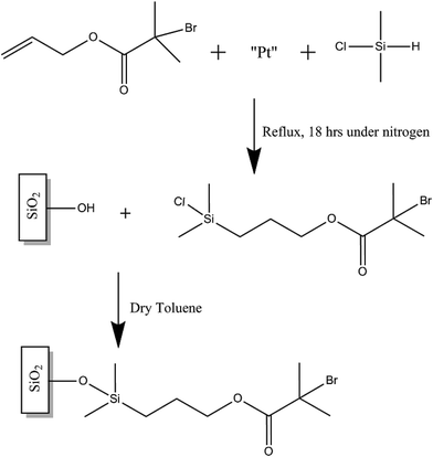
The synthesis of the initiator follows a modified methodology described by Ramakrishnan et al.27 Allyl 2-bromo-2-methylpropionate (1.6 mL), dimethylchlorosilane (10 mL) and platinum on carbon (10 mg) were added to a 25 mL round bottom flask. The system was purged with nitrogen and then the mixture was refluxed under nitrogen for 18 h. The excess silane was then distilled off. The resultant solution was quickly filtered through an acetate filter and then dried over anhydrous sodium sulphate to produce the colourless oil 3-[chloro(dimethyl)silyl]propyl 2-bromo-2-methyl-propanoate initiator, which was confirmed by 1H and 13C NMR using a Bruker AVIIIHD500 FT-NMR spectrometer in CDCl3 at 298 K. A clean 1 cm2 silicon nitride coated silicon wafer piece was then immediately immersed in a 2.5 mM solution of the self-assembling initiator and left submerged for 18 h as seen in Fig. 1. The piece was then taken out of the solution and briefly sonicated in ethanol before being dried in a stream of nitrogen gas. The initiator-modified piece was used immediately to graft polymer brushes following the steps described below.2.3 SI-ATRP ARGET of MMA
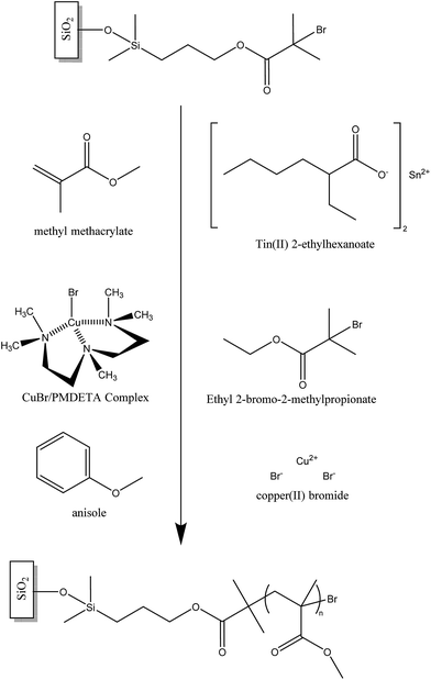
To conduct the SIP a 15 mL vial containing a 1 cm2 piece of the previously initiator-modified silicon nitride substrate was charged with MMA (7 mL, 0.065 mol), CuBr2 (0.0028 g, 0.0125 mmol), PMDETA (26 μL, 0.125 mmol), EBIB (0.048 g, 0.25 mmol) and 6 mL of anisole as solvent. A solution of tin(II) 2-ethylhexanoate (130 μL, 0.125 mmol) in anisole (1 mL) was then added using a hypodermic syringe inserted through the septum and the vial was placed in a thermostatic water bath at 70 °C. To stop the polymerisation, the vial was unscrewed, thereby exposing the catalyst to air. The modified substrate was then removed and briefly sonicated in tetrahydrofuran (THF) and dried in a stream of nitrogen gas.2.4 Polymer brush characterisation
The initiator and polymer brushes were analysed using X-ray Photoelectron Spectroscopy (XPS) on a ThermoFisher Scientific Theta Probe spectrometer (East Grinstead, UK) with a monochromated Al Kα X-ray source (hν = 1486.6 eV). An X-ray spot of ca. 400 μm radius was employed. Survey spectra were acquired employing a pass energy of 300 eV. High resolution, core level spectra for C 1s, O 1s, N 1s, Si 2p and Sn 3d were acquired with a pass energy of 50 eV. High resolution core level spectra for Cu 2p3 was acquired with a pass energy of 80 eV whilst a pass energy of 150 eV was used to acquire Br 3d. All spectra were charge referenced against the C 1s peak at 285 eV to correct for charging effects during acquisition.A spectroscopic ellipsometer (M2000, Woollam, USA) was used to determine the thicknesses of the PECVD-deposited silicon nitride layer and the polymer films produced on the silicon nitride surface. The incident wavelength was varied between 200–1700 nm and the resultant values were modelled using the commercially available CompleteEASE software (Woollam, USA). When measuring the polymer film a Cauchy layer was applied on top of the silicon nitride model.
Gel permeation chromatography (GPC) was used to measure molecular weights of the polymers formed in solution under the same conditions. The polymer samples were analysed with RALLS on a Viscotek 302 chromatograph equipped with refractive index, viscosity and light scattering detectors and 2 × 300 mm PLgel 5 μm mixed C columns, THF was used as the eluent with a flow rate of 1.0 mL min−1 at a constant temperature of 35 °C. Molecular weights were obtained using triple detection, where the detectors were calibrated with a single narrow molecular weight distribution polystyrene standard using a value of dn/dc of 0.185 mL g−1. The analysis was carried out using a dn/dc value of 0.085 mL g−1.
2.5 Lateral force microscopy with colloidal probes
To evaluate the friction behaviour of the polymer brushes on silicon nitride in a hybrid contact, the polymer-modified surfaces were tested using lateral force microscopy with steel colloidal probes. All lateral force microscopy testing was performed in ambient air, water or PAO at room temperature using an atomic force microscope (MAC Mode III, 5500 Scanning Probe Microscopy, Agilent Technologies, USA). PicoView 1.12 and PicoImage Basics 6.0 (Agilent Technologies, USA) software were used for data acquisition and image analysis, respectively. Colloidal probes were fabricated by attaching a steel ball (6.19–6.49 μm diameter) to a tipless cantilever by using two part epoxy adhesive.32,33 The actual spring constant of the modified tip was calculated by internal built-in thermal noise methods.34 Normal forces were calibrated by measuring the deflection sensitivity (nm V−1) from the slope of the linear part of a force–displacement curve obtained on a flat silicon surface. The normal force, FN, was set to zero at the point where the cantilever left the surface. The actual friction force is then calculated by averaging the forward and reverse scans. To determine the friction values of the polymers with respect to load area friction maps were completed. Areas of 4 μm × 4 μm consisting of 512 lines were scanned at a speed of 8 μm s−1 (1 line per s). The load was increased stepwise in steps of 20 nN every 400 nm to a maximum load of 180 nN depending on the probe, ensuring that at least 50 lines were attributed to each load. A minimum of three scans at different locations were carried out.3. Results
3.1 Polymerisation of MMA
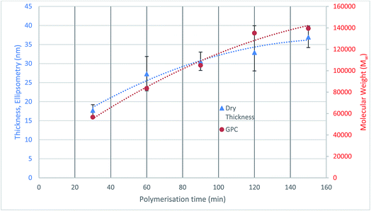
The initiator functionalised silicon nitride surface was analysed using sessile drop contact angle (CA) measurements to check the coverage and quality of the attached initiator monolayers. The CA results show that the modified surface has an increased contact angle of 83.0° ± 3.0° compared to 27.2° of the bare silicon nitride, which confirms that the surface modification has occurred.2The polymerisation was also quantified through the thickness analysis of the polymer films formed at different polymerisation durations using ellipsometry. The thickness of the polymer formed on silicon nitride was measured at three random locations on each sample, and the average value was plotted against polymerisation time (Fig. 3). The results show that as the polymerisation time increases, the polymer on the surface is growing thicker.
The molecular weight of the polymers formed at different durations are also plotted on Fig. 3. It can be seen that the thickness of the dry polymer film on the surface correlates well with the molecular weight of the polymer formed in solution at the same polymerisation time. A 37 nm thick polymer film has been formed in 150 min polymerisation time. The polymer brushes were not analysed with respect to surface morphologies as when they are immersed in a good solvent the measurements taken would not be relevant. Under these conditions within the lubrication system roughness and morphology are unlikely to play a large role in determining friction.7
3.2 XPS spectra
To confirm the initiator bonding and polymer formed on the silicon nitride surface, XPS analysis was conducted on the silicon nitride and silicon nitride surfaces modified with initiator and polymer (see Fig. 4). Line scans were performed on both initiator and polymer modified surfaces so that the X-ray spot did not reside on any area of the sample for more than 2–3 minutes. The multi-level lines can data for each element was collected and averaged during processing of the XPS data.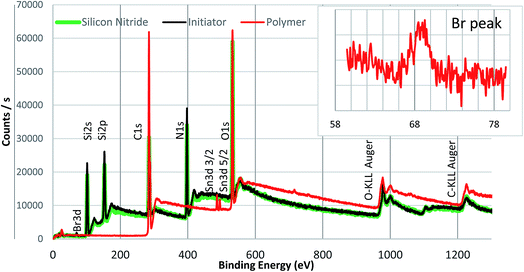 | ||
| Fig. 4 Survey scan of PMMA with peaks assigned. The inset shows a zoomed in spectrum of the Br peak present in the polymer. | ||
Compared to the bare silicon nitride surface, an additional weak peak for Br 3d at ca. 68 eV was observed in the spectrum of the initiator modified silica nitride surface, which confirmed the Br-containing initiator was successfully attached onto the silicon nitride surface. In addition, a carbon peak at 285 eV was observed on both bare and initiator modified silicon nitride surfaces due to adventitious carbon present on all XPS samples. The presence of a bromine peak indicates that the end group functionality of the initiator layer is intact, which is the key for the subsequent steps of polymerisation that are dependent on the alkyl halide bond cleavage (as illustrated in Fig. 2). The absence of Cl peak is clearly shown in XPS spectrum for the initiator-modified surface, indicating that no chlorine residuals exist in the initiator-modified surface layer and the initiators fully bonded to the substrate through complete hydrolysis of the Si–Cl bond. The survey spectra of a PMMA brush formed on the silicon nitride surface is also shown in Fig. 4. With respect to the polymer the lack of a Si or N signal indicates the silicon nitride surface was fully covered by a thick polymer film.
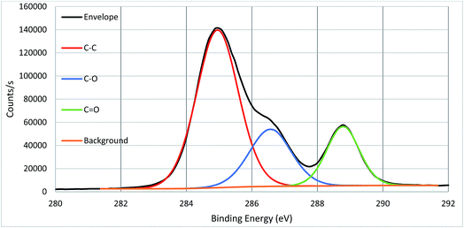
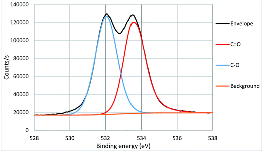
High resolution core spectra from PMMA formed on the silicon nitride substrate, as seen in Fig. 5 and 6, show the development of the oxygen and carbon peaks. The shape of the C 1s peak is used to define the carbon species present in the surface layer. The carbon spectrum is made up of three distinct peaks, due to the three different bonding environments of the carbon present in the polymer. Typically the main peak of C 1s at ca. 285.0 eV is assigned to C–C and C–H bonds in hydrocarbon backbone of PMMA, a shoulder (or asymmetry or a distinct peak) at 286.5 eV is from C–O functional groups as in alcohols, ethers or esters such as in PMMA. The peak at 289.0 eV is assigned to C![[double bond, length as m-dash]](https://www.rsc.org/images/entities/char_e001.gif) O bond in the ester groups of PMMA. The two peaks for O 1s in Fig. 3 indicate two different bonding environments exit for oxygen species, namely C
O bond in the ester groups of PMMA. The two peaks for O 1s in Fig. 3 indicate two different bonding environments exit for oxygen species, namely C![[double bond, length as m-dash]](https://www.rsc.org/images/entities/char_e001.gif) O and C–O bonds in the ester groups formed within the polymer PMMA on the surface. The ratio of oxygen and carbon in their respective states is expected due to the stoichiometry of PMMA. Both high resolution core spectra of C 1s and O 1s confirm that the ester groups exist in the polymer structures, and the polymer PMMA was successfully formed onto the surface as shown in Fig. 2. Core spectra as shown inset in Fig. 4 shows the presence of Br meaning that end group functionality is retained.
O and C–O bonds in the ester groups formed within the polymer PMMA on the surface. The ratio of oxygen and carbon in their respective states is expected due to the stoichiometry of PMMA. Both high resolution core spectra of C 1s and O 1s confirm that the ester groups exist in the polymer structures, and the polymer PMMA was successfully formed onto the surface as shown in Fig. 2. Core spectra as shown inset in Fig. 4 shows the presence of Br meaning that end group functionality is retained.
3.3 Friction behaviour of the polymer brushes
To explore the lubricating properties of the polymer coatings, the silicon nitride coated silicon wafer as well as polymer brush modified surfaces were tested against a steel colloidal probe using lateral force microscopy under a range of nano-Newton loads. The surface was tested under dry, water and PAO oil lubricated conditions to evaluate its friction behaviour. For each test the stepped friction maps were completed in three different areas then averaged for load.The water lubricated test results with a 6.19 μm probe resulted in friction forces are shown in Fig. 8. It can be seen that all polymer brush modified surfaces show higher friction force compared that of the bare silicon nitride surface in the water-lubricated sliding test. No obvious trend is seen between polymer brush thickness and the resultant friction force.
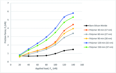 | ||
| Fig. 8 Friction force, FF, as a function of load, FN, for the polymer lubricated with water, measured with CFM. | ||
Compared with the dry sliding tests on the bare silicon nitride, the friction force is much lower under water lubricated conditions, which is not true for the polymer brushes. All the polymer modified surfaces follow a similar trend with a sharp increase in friction force occurring at a load of around 100 nN. This is also true for the bare silicon nitride surface, where there is a slight increase in friction force. Silicon nitride also performs much better for lower load than the polymer with no noticeable gradient until a load of 80 nN is reached. Therefore water is not a good solvent for the polymer brushes in the hybrid contact.
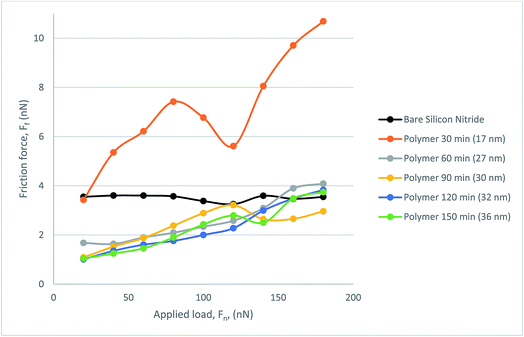
Fig. 9 presents the frictional response of the steel colloid in PAO on bare silicon nitride and on the polymer coated samples. All polymer samples successfully provided a lubricating effect at all loads which resulted in a lower friction force than on bare silicon nitride. The thinnest polymer, although outperforming bare silicon nitride, degraded under load. Although it was subject to degradation, this thickness of polymer still reduced the friction within the hybrid contact. A somewhat similar trend is present when observing the behaviour of the 27 nm polymer. Above a load of 120 nN the lubricating properties of the polymer degrade almost linearly up to the maximum load of 180 nN. At this load the frictional force is indistinguishable from the force experienced with the 17 nm polymer. The resultant three polymers follow a similar trend with a low mean average error (0.188 nN).
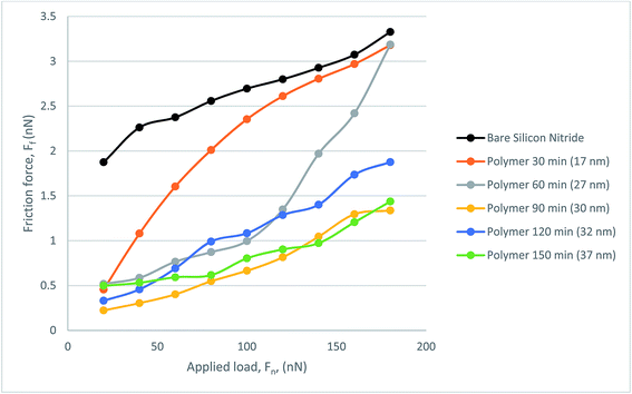 | ||
| Fig. 9 Friction force, FF, as a function of load, FN, for the polymer lubricated with PAO, measured with CFM. | ||
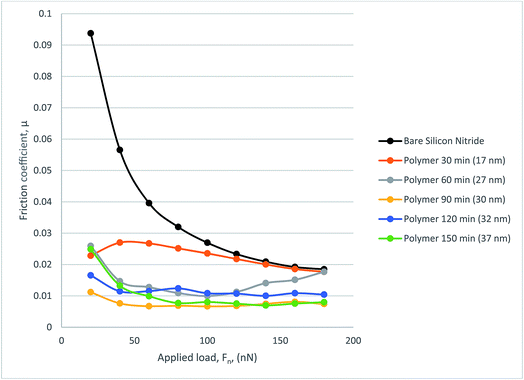
Fig. 10 gives coefficient of friction data. The COF data from the 17 nm polymer shows degradation under load as expected from the frictional force graph. A similar trend can be seen from 27 nm polymer in which the additional load means that at 120 nN the COF rises to just below that of bare silicon nitride. The remaining polymers perform well with COF decreasing with increasing load as occurs with some polymers. The thicker polymers tend to show a much more stable COF result with the lowest COF being recorded at 0.00665.
4. Discussion
4.1 Surface preparation and polymerisation
The synthesis of methyl methacrylate polymers both in solution and surface initiated has been widely reported in the literature mainly through the use of free radical polymerisation techniques.35 In this study MMA has uniquely been grafted from a silicon nitride surface using a process that is commonly performed on silicon wafer substrates. A primary objective of SI-ATRP is for complete initiator coverage onto the silicon nitride surface to facilitate polymerisation. As expected, the initiator monolayer formation took 18 hours, which is much longer than other well-known SAMs such as octadecyltrichlorosilane that typically take less than 2 hours to form.1 This is a result of steric hindrance due to the two methyl groups and a larger terminal group on the silane.2 A maximum contact angle of 83° has been achieved using a 2.5 mM solution of the initiator in toluene over 18 h.Although high grafting densities are possible for initiators it cannot be assumed that all of these initiator sites will be utilised for SI-ATRP.36 Based on eqn (1), the molecular weight (Mw) can be estimated from the grafting density (σ), thickness (d, nm), density (p, g cm−3) and Avogadro's number It is reported in the literature that grafting densities can approach 1 chain per nm2 for “grafting from” strategies, PMMA is thought to have a grafting density and density of 0.7 chains per nm2 and 1.188 g cm−3 respectively.2,7
 | (1) |
The equation above is often used to estimate molecular weight however, the results should be treated with caution as can be seen below. The theoretical Mw values calculated based on the equation above are shown in Table 1. These estimates can then be compared to the GPC measurements. By rearranging eqn (1) above, theoretical thickness can also be calculated from the molecular weight obtained by GPC.
| Theoretical Mw from measured thickness | Theoretical thickness from measured Mw | ||
|---|---|---|---|
| Thickness (nm) | Theoretical Mw | Mw | Theoretical thickness (nm) |
| 17 | 17![[thin space (1/6-em)]](https://www.rsc.org/images/entities/char_2009.gif) 374 374 |
56![[thin space (1/6-em)]](https://www.rsc.org/images/entities/char_2009.gif) 608 608 |
55.38 |
| 27 | 27![[thin space (1/6-em)]](https://www.rsc.org/images/entities/char_2009.gif) 594 594 |
83![[thin space (1/6-em)]](https://www.rsc.org/images/entities/char_2009.gif) 439 439 |
81.64 |
| 30 | 30![[thin space (1/6-em)]](https://www.rsc.org/images/entities/char_2009.gif) 660 660 |
105![[thin space (1/6-em)]](https://www.rsc.org/images/entities/char_2009.gif) 034 034 |
102.77 |
| 32 | 32![[thin space (1/6-em)]](https://www.rsc.org/images/entities/char_2009.gif) 704 704 |
135![[thin space (1/6-em)]](https://www.rsc.org/images/entities/char_2009.gif) 140 140 |
132.22 |
| 37 | 36![[thin space (1/6-em)]](https://www.rsc.org/images/entities/char_2009.gif) 792 792 |
139![[thin space (1/6-em)]](https://www.rsc.org/images/entities/char_2009.gif) 477 477 |
136.47 |
The significant discrepancies in either thickness or molecular weights estimated from ellipsometry and GPC approaches may possibly result from the swelling effects of the polymer brushes grafted to the silicon nitride surface. Ellipsometry measures the thickness of the polymer film on a dry surface, in which the polymer is not hydrated and will be in a collapsed state. This is clearly not comparable to GPC for two reasons: on one hand, the polymer is dissolved in the solvent for GPC measurement, thus in hydrated/swollen state; on the other hand, the GPC data is based on free polymer produced in solution where there will be less steric hindrance for the polymer growth. In addition, the actual grafting density may also be different to that reported in the literature. Bielecki et al. also pointed out that under a good solvent poly(dodecyl methacrylate) achieved nine-fold step height changes, well within the limits calculated here.7
4.2 Tribological performance
The tribological performance of the polymer brushes formed on silicon nitride has been evaluated using a spherical steel colloidal probe under applied loads up to 180 nN during sliding testing. The bare silicon nitride and modified surfaces were tested under dry, water and PAO lubricated conditions.In the case of dry tests, a small reduction in friction was achieved when the thickness of the polymer brushes was sufficiently high (>17 nm) and under relatively low loads (<150 nN). Hence the polymer brush has provided a certain level of lubrication to the dry hybrid contact. When the polymer brush layer is very thin, it is susceptible to the probe gouging through the polymer thus resulting in higher friction. In the case of the dry polymer brush the collapsed polymer brush will be very resistant to the leading edge of the probe resulting in high shear forces as the probe travels through the brushes. When comparing this to the well know low friction hybrid contact the collapsed polymer brush is likely to hinder the friction force recorded. Due to atmospheric humidity, higher adhesion may occur due to the formation of a water meniscus between the contacting surfaces since PMMA is known to be susceptible to moisture.13
Under the PAO oil lubricated conditions, the polymer brushes formed on silicon nitride have significantly reduced the friction of the hybrid contact, and generally the thicker the polymer brush, the lower the friction force observed. A maximum reduction of >2 nN in FF was obtained with the polymer brushes 30 nm thick. The swelling of PMMA brushes in PAO is key to the lubricious qualities of the polymer film. The ability of this synergistic solvent allows the polymer brush to fulfil the aforementioned criteria of polymer brush lubrication. The variation of thickness and the resultant friction force shows a trend that is somewhat similar to that previously reported, in which the strong resistance of compression at higher loads is dealt with more successfully with longer brush length.19 The higher loads applied during lateral force microscopy on thicker, longer chain polymers result in a lower friction characteristic, considered to be an effect of grafting density and reduced interaction with the probe through repulsive forces, in agreement with Casoli et al.37 The long chain polymer brush is thought to act more like a solid which requires a higher external pressure to impart movement in the brush system. This is due to the repulsion of brush–brush interaction within the system which gives rise to entropic stabilisation. Also key to the low friction force is the grafting density of the polymer brush, as has been shown by multiple researchers comparing spin-coated or adsorbed PMMA samples and the corresponding tribological results.19,38 Yamamoto et al. also concludes that a higher density of PMMA results in a higher repulsive ability in addition to more resistance to compression.39
However, the friction of the polymer brush modified hybrid contact was increased when lubricated by water for all the polymer brush thicknesses even under the lowest load of 20 nN. As discussed above, the performance of polymer brushes relies on the swelling effects when a solvent is involved. Since PMMA is insoluble in water, the polymer brushes will be collapsed when the contact is lubricated by water thus not providing any repulsion of the probe or lubrication effect. This may give some understanding to the frictional response, it is likely that the stretched out brush conformation is not present resulting in a poor frictional response. The relative success of the bare silicon nitride contact may be due to the hydrated silicon layer offering a lubricating effect.40 Sakata et al. also suggested that in a poor solvent, PMMA brushes may prefer to interact with stainless steel probes and result in a relatively high friction force.38 No clear relationship between the thickness and FF was found in water lubricated PMMA brushes.
5. Conclusion
Poly(methyl methacrylate) brushes were successfully grown from silicon nitride substrate using surface initiated techniques. Atom radical transfer polymerisation coupled with activators regenerated by electron transfer has been shown, through multiple characterisations, to successfully produce polymer brushes on silicon nitride. After confirmation of a successful SIP the polymer brushes were tribologically tested for the first time using a steel colloidal modified AFM cantilever to replicate the hybrid contact. The main conclusions are:• Up to 37 nm thick PMMA polymer brushes have been formed on silicon nitride within 150 minutes using a controlled ARGET ATRP method. The polymer brush chemistry and film thickness have been confirmed by the contact angle, XPS and ellipsometry measurements. The XPS results show that the polymers are well-defined and retain the end group functionality. The XPS core spectra also show that carbon and oxygen exist in different bonding forms and their contributions to each elemental signal are in the expected ratios as per PMMA stoichiometry.
• Nanotribological tests with colloidal probes have shown that the polymer film formed on silicon nitride performed differently under different lubrication conditions:
◦ Under dry conditions, the polymer brushes slightly reduced the friction between the hybrid contacts as a lubricant;
◦ Under water lubricated conditions, the polymer brushes do not reduce the friction for the hybrid contacts due to collapsing of the polymer chains in water.
◦ The polymer brushes reduced the friction significantly when tested in PAO oil where the swelling effects are clearly seen. A maximum reduction of over 2 nN FF (approx. 25%) was obtained with 30 nm polymer brushes when compared to bare silicon nitride.
◦ COF values less than 0.0067 can be achieved by using 30 nm polymer brushes lubricated with PAO.
The results obtained here, in the nano Newton-scale, show promise for lubricating the hundreds of mega-Pascal range in which bearings operate. Further work is looking at Newton-scale replication of the polymer brush solution for hybrid bearings. These results shown in this article indicate that the application of surface initiated PMMA polymer brushes could be a successful lubrication solution to the challenging problem of lubricating hybrid contacts in oil lubricated conditions.
Conflicts of interest
There are no conflict of interest to declare.Acknowledgements
The authors acknowledge the financial support from the Defence Science and Technology Laboratory (DSTL, DSTLX1000093632), which is part of the UK's Ministry of Defence and from EPSRC (Grant EP/M50662X/1) to this project. The authors also wish to thank N. Wells, A. Clark and D. Gropper/C. Cosher for assistance with NMR, SEM and proofreading respectively.References
- L. Wang, M. Nie and J. Rumbol, Tribol.-Mater., Surf. Interfaces, 2012, 6, 75–83 CrossRef CAS.
- S. Watson, M. Nie, L. Wang and K. Stokes, RSC Adv., 2015, 5, 89698–89730 RSC.
- L. Wang and R. J. K. Wood, Tribol. Int., 2009, 42, 1629–1637 CrossRef CAS.
- L. Wang, R. J. K. Wood, T. J. Harvey, S. Morris, H. E. G. Powrie and I. Care, Wear, 2003, 255, 657–668 CrossRef CAS.
- H. Spikes, Lubr. Sci., 2008, 20, 103–136 CrossRef CAS.
- A. Olivier, F. Meyer, J.-M. Raquez, P. Damman and P. Dubois, Prog. Polym. Sci., 2012, 37, 157–181 CrossRef CAS.
- R. Bielecki, E. Benetti, D. Kumar and N. Spencer, Tribol. Lett., 2012, 45, 477–487 CrossRef CAS.
- R. Bielecki, M. Crobu and N. Spencer, Tribol. Lett., 2013, 49, 263–272 CrossRef CAS.
- R. Bielecki, P. Doll and N. Spencer, Tribol. Lett., 2013, 49, 273–280 CrossRef CAS.
- J. Klein, Annu. Rev. Mater. Sci., 1996, 26, 581–612 CrossRef CAS.
- J. Klein, Y. Kamiyama, H. Yoshizawa, J. N. Israelachvili, G. H. Fredrickson, P. Pincus and L. J. Fetters, Macromolecules, 1993, 26, 5552–5560 CrossRef CAS.
- J. Klein, E. Kumacheva, D. Mahalu, D. Perahia and L. J. Fetters, Nature, 1994, 370, 634–636 CrossRef CAS.
- N. S. Bhairamadgi, S. P. Pujari, F. A. M. Leermakers, C. J. M. van Rijn and H. Zuilhof, Langmuir, 2014, 30, 2068–2076 CrossRef CAS PubMed.
- M. Chen, W. H. Briscoe, S. P. Armes, H. Cohen and J. Klein, Eur. Polym. J., 2011, 47, 511–523 CrossRef CAS.
- L. J. T. Landherr, C. Cohen, P. Agarwal and L. A. Archer, Langmuir, 2011, 27, 9387–9395 CrossRef CAS PubMed.
- B. Li, B. Yu, Q. Ye and F. Zhou, Acc. Chem. Res., 2015, 48, 229–237 CrossRef CAS PubMed.
- Q. Wei, M. Cai, F. Zhou and W. Liu, Macromolecules, 2013, 46, 9368–9379 CrossRef CAS.
- S. Edmondson, V. L. Osborne and W. T. S. Huck, Chem. Soc. Rev., 2004, 33, 14–22 RSC.
- S. Yamamoto, M. Ejaz, Y. Tsujii, M. Matsumoto and T. Fukuda, Macromolecules, 2000, 33, 5602–5607 CrossRef CAS.
- T. Pintauer and K. Matyjaszewski, Coord. Chem. Rev., 2005, 249, 1155–1184 CrossRef CAS.
- K. Matyjaszewski and J. Xia, Chem. Rev., 2001, 101, 2921–2990 CrossRef CAS PubMed.
- D. A. Shipp and K. Matyjaszewski, Macromolecules, 2000, 33, 1553–1559 CrossRef CAS.
- A. M. Elsen, J. Burdyńska, S. Park and K. Matyjaszewski, ACS Macro Lett., 2013, 2, 822–825 CrossRef CAS.
- K. Matyjaszewski, H. Dong, W. Jakubowski, J. Pietrasik and A. Kusumo, Langmuir, 2007, 23, 4528–4531 CrossRef CAS PubMed.
- S. Jahn and J. Klein, Macromolecules, 2015, 48, 5059–5075 CrossRef CAS.
- A. T. Nguyen, J. Baggerman, J. M. J. Paulusse, C. J. M. van Rijn and H. Zuilhof, Langmuir, 2011, 27, 2587–2594 CrossRef CAS PubMed.
- A. Ramakrishnan, R. Dhamodharan and J. Rühe, Macromol. Rapid Commun., 2002, 23, 612–616 CrossRef CAS.
- A. Halperin and E. B. Zhulina, Langmuir, 2010, 26, 8933–8940 CrossRef CAS PubMed.
- T. Kreer, Soft Matter, 2016, 12, 3479–3501 RSC.
- M. Kumar Vyas, K. Schneider, B. Nandan and M. Stamm, Soft Matter, 2008, 4, 1024–1032 RSC.
- E. Kutnyanszky and G. J. Vancso, Eur. Polym. J., 2012, 48, 8–15 CrossRef CAS.
- W. A. Ducker, T. J. Senden and R. M. Pashley, Nature, 1991, 353, 239–241 CrossRef CAS.
- J. Lee, J. Pharm. Sci., 2004, 93, 2310–2318 CrossRef CAS PubMed.
- J. Zekonyte, A. Cavaleiro and T. Polcar, Appl. Surf. Sci., 2014, 303, 381–387 CrossRef CAS.
- H. Gao and K. Matyjaszewski, Prog. Polym. Sci., 2009, 34, 317–350 CrossRef CAS.
- H. Ma, J. a. He, X. Liu, J. Gan, G. Jin and J. Zhou, ACS Appl. Mater. Interfaces, 2010, 2, 3223–3230 CAS.
- A. Casoli, M. Brendlé, J. Schultz, P. Auroy and G. Reiter, Langmuir, 2001, 17, 388–398 CrossRef CAS.
- H. Sakata, M. Kobayashi, H. Otsuka and A. Takahara, Polym. J., 2005, 37, 767–775 CrossRef CAS.
- S. Yamamoto, M. Ejaz, Y. Tsujii and T. Fukuda, Macromolecules, 2000, 33, 5608–5612 CrossRef CAS.
- H. Hyuga, Y.-i. Yoshizawa, K. Hirao, D. Amutha Rani and M. I. Jones, Int. J. Appl. Ceram. Technol., 2008, 5, 111–118 CrossRef CAS.
| This journal is © The Royal Society of Chemistry 2017 |

