DOI:
10.1039/C7RA08816G
(Paper)
RSC Adv., 2017,
7, 49105-49113
Crystal structure transformation and step-by-step thermal decomposition behavior of dihydroxylammonium 5,5′-bistetrazole-1,1′-diolate†
Received
9th August 2017
, Accepted 8th October 2017
First published on 20th October 2017
Abstract
The crystal structure transformation and step-by-step thermal decomposition behavior of dihydroxylammonium 5,5′-bistetrazole-1,1′-diolate (TKX-50) under thermal stimulation were studied and the whole process included thermal expansion, primary decomposition and secondary decomposition. The thermal expansion and primary decomposition of TKX-50 were studied using in situ powder X-ray diffraction (in situ XRD) together with Rietveld refinement, by which the crystal structure transformation process can be accurately traced. The results showed that the thermal expansion of TKX-50 was anisotropic. In particular, the a-axis exhibited a negative thermal expansion (NTE) that may be attributed to the distortion of the six-membered ring, which results in H-transfer between the cation and dianion. The crystal structure of the intermediate product after primary decomposition was also obtained. The secondary decomposition process was analysed using thermogravimetric-differential scanning calorimetry (TG-DSC) due to the safety risk of TKX-50 analyzed by in situ XRD. The crystal structure transformation process from TKX-50 to the intermediate product under heat stimulation was deduced. Meanwhile, the morphological change of the whole process was obtained using hot stage microscopy (HSM). Combined with TG-FTIR technology, the gaseous decomposition products at each step were analysed and the thermal decomposition mechanism of TKX-50 was proposed. This study further reveals the thermal decomposition behavior of TKX-50 and is helpful for better understanding the thermal decomposition mechanism.
1. Introduction
The synthesis of high performance energetic materials with low sensitivity has become a long-term target for military and civilian applications. Compared with traditional CHON explosives, research of energetic ionic salts has shown major developments and energetic ionic salts have attracted wide attention due to their considerable properties.1–17 For example, energetic ionic salts have a higher positive enthalpy of formation due to the large number of N–N and N–C bonds, lower friction and impact sensitivity and better oxygen balance. Moreover, energetic ionic salts are environmental friendly due to the fact that the main decomposition gas is N2. As a typical energetic ionic salt, TKX-50 has attracted considerable attention. First of all, TKX-50 is more insensitive. For example, the friction sensitivity (120 N) of TKX-50 is lower than that of β-HMX (112 N) and ε-CL-20 (48 N), and the impact sensitivity (20 J) of TKX-50 is also lower than that of TNT (15 J), RDX (7.5 J), β-HMX (7 J) and ε-CL-20 (4 J). At 298 K, the crystal density of TKX-50 is close to that of β-HMX. The calculated detonation velocity of TKX-50 is 9698 m s−1 and the estimated detonation velocity is 9560 ± 280 m s−1 in the new study, which is higher than that of TNT (7459 m s−1), RDX (8983 m s−1), β-HMX (9221 m s−1) and ε-CL-20 (9455 m s−1).18,19
Based on the excellent performance of TKX-50, a lot of research has been carried out. In particular, explosives and their components often need to be stored for quite a long time before use and the thermal decomposition reactions and the decomposition mechanism of explosives are very important to their stability. Fischer20 firstly studied the thermal behavior of TKX-50 using differential scanning calorimetry (DSC) and thermogravimetric analysis (TGA). It was found that the thermal decomposition process includes two stages and the first stage starts at 210–250 °C depending on the heating rate. The decomposition kinetic parameters of TKX-50 have been calculated mainly using Kissinger and Ozawa’s method and the results were in different ranges depending on the test condition.21–23,29 The structural stability and chemical stability of TKX-50 under high pressure and high temperature were discussed based on Raman spectroscopy results and the intermediates at high pressure were attributed to a suppression of H-transfer.24 The structural response of TKX-50 under high pressure was studied and the experimental results showed that TKX-50 exhibits a highly anisotropic compression, with an anomalous compression of the a-axis, which was explained by the hydrogen bonds.25
Regarding the primary thermal decomposition mechanism, Qi An found that proton transfer from the cation to the dianion decreases the reaction barrier and initiates decomposition.26 Liya Meng studied the influences of strong hydrogen bonds on the stability of TKX-50 and found that strong hydrogen bonds easily promote H-transfer, which accelerates thermal decomposition.27 Sinditskii further investigated the thermal decomposition under non- and isothermal conditions, proposed the thermal decomposition mechanism of TKX-50 and found that the free hydroxylamine formed in the dissociation reaction determines the decomposition of TKX-50. What’s more, he inferred that diammonium 5,5′-bistetrazole-1,1′-diolate (ABTOX) is an intermediate decomposition product based only on Fourier transform infrared spectroscopy (FTIR).28 Recently, Muravyev considered that the decomposition of bistetrazole diol (BTO) is the key process in the thermal decomposition of TKX-50, also proposed the thermal decomposition mechanism based on TGA and DSC and directly identified ABTOX to be the most important intermediate of the decomposition process. The authors found no trace of H2O in the first stage of TKX-50 decomposition.29 Zhipeng Lu found that a phase transition facilitates H-transfer and produces final small stable molecules including NH3 and H2O based on Raman spectroscopy, thermogravimetric-differential scanning calorimetry (TG-DSC) and ab initio calculations. In other words, the phase transition promotes the decomposition of TKX-50.30 However, accurate crystal structure information has not been obtained due to the limited temporal–spatial resolution of existing analytical methods and so further research is needed to observe the evolution process of related structures in situ.
Although the thermal decomposition behavior of TKX-50 has received extensive attention, the crystal structure transformation behavior has received less consideration. In particular, the behavior of the crystal structure from thermal expansion to thermal decomposition has not been studied, and the process of TKX-50 decomposition has mostly been studied using DSC, which analyses structural changes indirectly through thermal variation. However, on the DSC curve the partial heats of the exothermic process of the two-step decomposition overlap and it is difficult to distinguish the accurate thermal decomposition temperature of TKX-50. Additionally, the crystal structure change cannot be obtained using DSC. In particular, the crystal structure transformations from thermal expansion to primary decomposition to secondary decomposition are difficult to obtain by conventional DSC techniques. On the basis of previous work, in this paper, we have studied the thermal expansion behavior of TKX-50 using in situ XRD. It was found that anisotropic thermal expansion was the main process below 175 °C, leading to a change of intermolecular force and the expansion and flipping of some molecules. In particular, the expansion along the a-axis is a negative thermal expansion, which results in a shorter distance between the cation and dianion, thus inducing hydrogen transfer. With the increasing temperature, primary decomposition occurred and was also observed dynamically using in situ XRD, and the intermediate product was formed and confirmed as ABTOX by single crystal X-ray diffraction, which was consistent with the conclusion of the literature.28,29 Additionally, the crystal morphology change due to the anisotropy during the thermal expansion of TKX-50 and the process from thermal expansion to primary decomposition were observed using hot stage microscopy (HSM). The secondary decomposition process was analysed using TG-DSC due to the safety risk of the in situ XRD. The secondary decomposition occurred at around 280 °C. In addition, thermogravimetric-Fourier transform infrared spectroscopy (TG-FTIR) was applied to analyse the thermal decomposition gas products for each decomposition process. The thermal decomposition mechanism of TKX-50 was proposed and the related results further deepen the understanding of the relationship between the thermal stability and crystal structure of TKX-50.
2. Experimental
2.1 Materials and instrumentation
TKX-50 was provided by the Institute of Chemical Materials, China Academy of Engineering Physics and recrystallized by slow evaporation in water.
The powder X-Ray diffraction (PXRD) data were collected using a Bruker D8 Advance diffractometer using a Vantec detector with Cu Kα radiation. The tube current and voltage were 40 mA and 40 kV and the scan angle ranged from 10° to 50°.
The single crystal X-ray diffraction data were collected using a Bruker APEX-II CCD diffractometer with Mo Kα radiation at 296 K. The structure was solved by Intrinsic Phasing with the ShelXT structure solution program and refined using Least Squares minimization by the XL refinement package.
2.2 In situ structure transformation characterization using X-ray diffraction
In situ non-isothermal and isothermal powder X-ray diffraction were both carried out using a temperature programme. A TTK 450 temperature chamber was used to precisely control the temperature during the experiment. Non-isothermal in situ XRD was used to analyse the thermal expansion of TKX-50. The first scan started at 30 °C and the next scan was conducted at a 10 °C interval. When the temperature reached 120 °C, the scanning process changed to having a 5 °C interval up to 175 °C. The final scan was carried out when the temperature was decreased to 30 °C.
Isothermal in situ XRD was used to analyse the primary decomposition of TKX-50. The first scan data were collected when the temperature was increased from ambient to 30 °C, then the temperature was raised to 190 °C and the second scan was started after 10 minutes. The time interval was 10 minutes and after that a new scanning process was carried out. When such a process had been conducted 24 times, the temperature was decreased to 30 °C and the final data were collected. Except for the different target isothermal temperature, the same programme was applied for 192 °C, 194 °C, 196 °C and 198 °C. The time point at which the target temperature had just been reached was used as a zero reference.
2.3 In situ transformation observation using hot stage microscopy
Hot stage microscopy (HSM) of TKX-50 was performed using a Linkam LTS420 Heating and Cooling Stage. The crystal was mounted on the hot stage and observed using a Scope.A1 optical microscope by ZEISS. The morphological changes of TKX-50 were obtained under heat stimulation. The temperature was set from 30 °C to 198 °C and the heating rate was 10 °C min−1. When the temperature reached 198 °C, this temperature was maintained for 210 minutes. After this the temperature was decreased to 30 °C.
2.4 Thermogravimetric techniques
Thermogravimetric-differential scanning calorimetry (TG-DSC) technology was employed to analyse the secondary decomposition of TKX-50. The samples were obtained after the primary decomposition of TKX-50 using isothermal in situ XRD. The samples were tested in aluminum pans and the experiment was conducted at a heating rate of 10 °C min−1 from 30 °C to 400 °C with around 1.58 mg.
Thermogravimetric-Fourier transform infrared spectroscopy (TG-FTIR) was applied to analyse the gas products of each decomposition process. The temperature programme was set from 30 °C to 198 °C at a heating rate of 10 °C min−1, the isothermal time was 60 minutes, and the temperature was then increased up to 500 °C at the same heating rate. Finally, the temperature was decreased to 30 °C.
2.5 Crystal structure refinement using the Rietveld method
The Rietveld method in the TOPAS program of the Bruker Company was used to refine the obtained XRD diffraction patterns in order to obtain the lattice parameter changes and calculate the conversion degree influenced by the different temperatures. The instrument parameters used to analyse the lattice parameter changes are shown in Table 1 and the instrument parameters for calculating the conversion degree have been obtained from previous work.31 The fundamental principles of the Rietveld method have been mentioned in previous work.32
Table 1 Instrument parameters for Rietveld refinement
| Instrument parameter |
Value |
| Goniometer radius |
Primary |
217.5 |
| Secondary |
217.5 |
| Equatorial convolutions |
Receiving slit width/mm |
0.1750585 |
| FDS shape/° |
0.5 |
| Axial convolutions |
Source length/mm |
12 |
| Sample length/mm |
15 |
| RS length/mm |
12 |
| Prim. soller/° |
7.196213 |
| Sec. soller/° |
3.753572 |
3. Results and discussion
3.1 Morphological changes of TKX-50
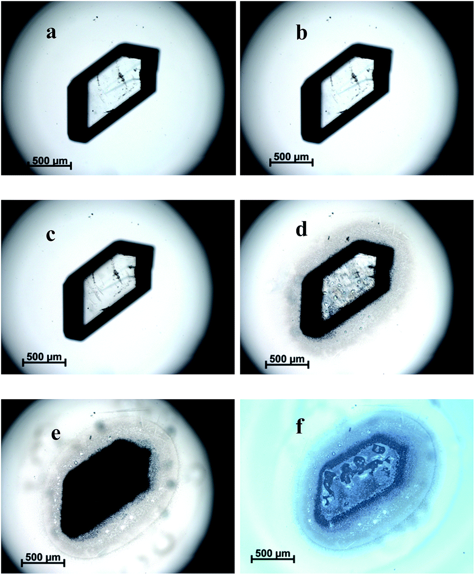
The morphological change process of TKX-50 under heat stimulation can be observed. From 30 °C to 175 °C, the crystal morphology remained basically unchanged. As the temperature increased to 198 °C, the crystal appearance began to change slowly. It was found that cracks appeared on the crystal and liquid formed with bubbles emerging from the crystal. It was deduced that the crystal began to decompose but not fully. After 150 minutes, most of the crystal had decomposed leaving some solid residues. Meanwhile, the crystal turned from transparent to opaque and from a single crystal to polycrystalline. It was presumed that the primary decomposition of TKX-50 had occurred and a stable intermediate product was formed. The primary solid phase decomposition reaction of TKX-50 was started from local active spots of the crystal that appeared to form the reaction core, which destroyed the molecular structure at the active spots, and then extended gradually to the crystal interior. The detailed images of TKX-50 under heat stimulation are shown in Fig. 1.
 |
| | Fig. 1 The morphological changes of TKX-50 under heat stimulation. (a) The morphology of TKX-50 at 30 °C; (b) the morphology of TKX-50 at 175 °C; (c) the morphology of TKX-50 when the temperature has just risen to 198 °C; (d) the morphology of TKX-50 when the temperature has risen to 198 °C and been maintained for 1 hour; (e) the morphology of TKX-50 after primary decomposition; (f) the morphology of TKX-50 after primary decomposition using the reflection mode of the microscope. | |
3.2 The thermal expansion of TKX-50
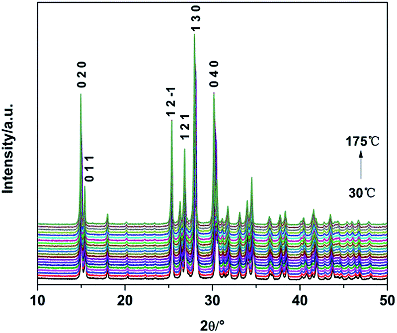
In order to further confirm the crystal structure transformation and decomposition process of TKX-50 under thermal stimulation, in situ non-isothermal XRD was applied to investigate the thermal expansion of TKX-50. XRD patterns of TKX-50 were collected within the temperature range from 30 °C to 175 °C (Fig. 2). During the heating process the diffraction peaks in the XRD patterns shifted toward a lower 2θ without other obvious changes, which indicates that lattice expansion has taken place. Using the TOPAS software combined with Rietveld refinement, the refined lattice parameters of TKX-50 corresponding to certain temperature points could be obtained (detailed in Table S1†) and the accurate thermal expansion coefficients were calculated. The refined lattice parameters of TKX-50 were expressed as a function of temperature.
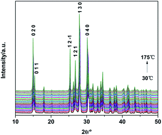 |
| | Fig. 2 XRD patterns of TKX-50 with increasing temperature from 30 to 175 °C. | |
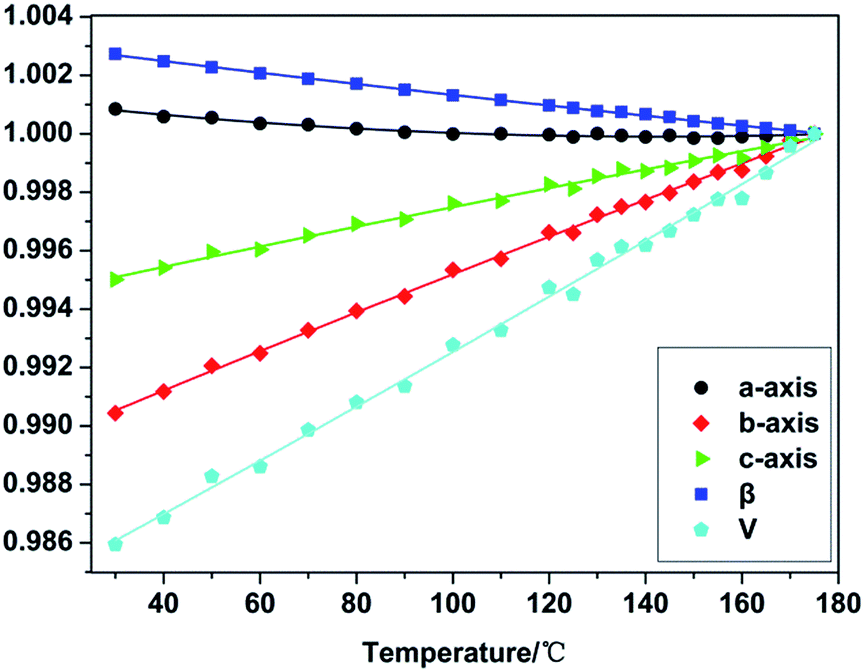
It was found that the value of the a-axis decreased to a certain extent and then kept fluctuating with the increasing temperature. The β angle also decreased with a −0.27% change from 30 °C to 175 °C. A negative thermal expansion (NTE) was exhibited. Meanwhile, it was observed that the value of the b-axis, c-axis and the unit cell volume all increased with the increasing temperature and the changes were 0.96%, 0.50% and 1.42%, respectively, which shows positive thermal expansion (PTE). The normalized changing lattice parameters can be fitted to a second-order polynomial (Fig. 3). Meanwhile, the thermal expansion coefficients were calculated using the formula α = 1/L (dL/dT), in which L represents the primary lattice constant.33 The average thermal expansion coefficients of the a-axis, b-axis, c-axis, β angle and the unit cell volume were −1.04635 × 10⁻⁶, 5.56149 × 10⁻⁶, 4.76293 × 10⁻⁶, −1.92479 × 10⁻⁷ and 2.2973 × 10⁻⁷, respectively. It was observed that the thermal expansion coefficient of each axis was different within the same temperature range. This revealed that the thermal expansion of TKX-50 was anisotropic. Corresponding to the morphology change from Fig. 1, although the anisotropy of the thermal expansion can lead to some change in crystal morphology, the anisotropic expansion will not cause significant change due to the fact that the crystal is in the state of free confinement, such as in cracking, grinding and so on.
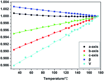 |
| | Fig. 3 Calculated unit cell parameters of TKX-50 normalized from 30 to 175 °C. | |
3.3 The primary decomposition of TKX-50
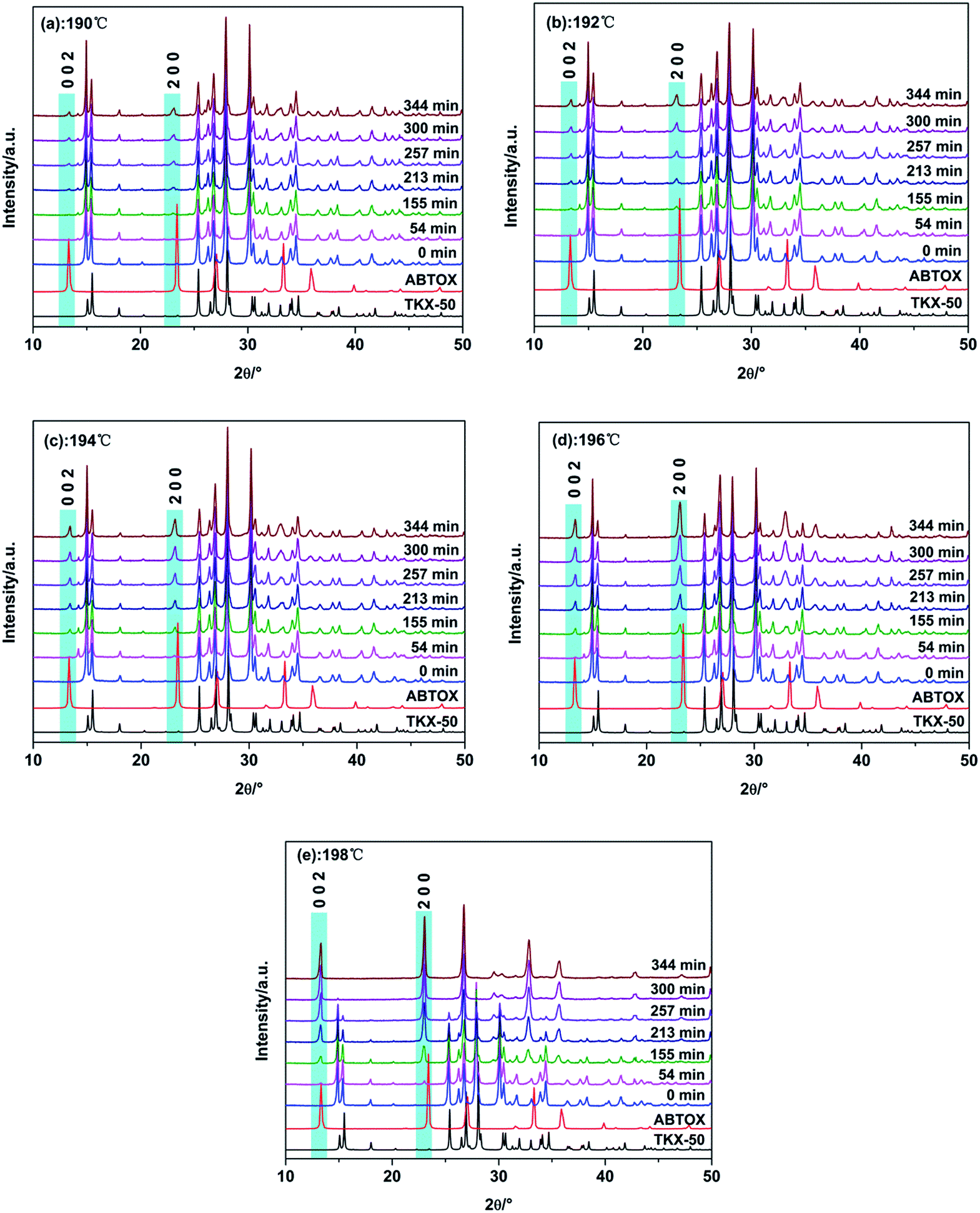
In situ isothermal X-ray diffraction was used to carry out heat treatment of TKX-50 at 190, 192, 194, 196 and 198 °C. In order to eliminate the influence of the sample orientation on the diffraction peaks, the raw materials were completely ground before use. The heating program was then applied. Thus we obtained the whole process of crystal structure variation at different temperatures and compared this with the single crystal simulation XRD patterns of TKX-50 and ABTOX. The detailed processes are shown in Fig. 4 and the conversion degree of TKX-50 to the intermediate product at all the isothermal temperatures is shown in Fig. 5.
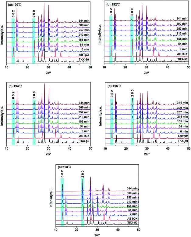 |
| | Fig. 4 (a–e) XRD patterns of TKX-50 at different isothermal temperatures. | |
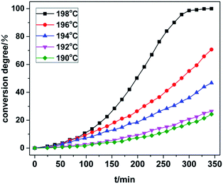 |
| | Fig. 5 Conversion degree of TKX-50 to the intermediate product at different isothermal temperatures. | |
From the XRD patterns at 190 °C and 192 °C, it can be seen that the peaks shifted toward a lower 2θ due to thermal expansion and new weak peaks appeared with the increasing heating time. The intensity of the new peaks increased and that of the peaks belonging to the raw materials decreased obviously at 194 °C. However, a small number of peaks of the raw TKX-50 still existed at 196 °C. When the temperature rose to 198 °C, the residual peaks of the raw material disappeared and new diffraction peaks appeared, in particular the (002) and (200) diffraction peaks. Moreover, the position of the new diffraction peaks coincided with the XRD pattern of ABTOX. We speculated that primary decomposition of TKX-50 occurred, but no crystalline transition occurred. Meanwhile, with increasing temperature the crystal structure changed more quickly. The results showed that the crystal structure changed under long time thermal stimulation. On the other hand, the XRD patterns at different temperatures were analysed and the conversion degrees for all the isothermal temperatures within the same time frame were all calculated. The final conversion degrees were 24.30%, 26.40%, 46.72%, 70.69% and 100% using the Rietveld method. With the increase of heating time, the conversion degree increased. The conversion degree was higher at higher isothermal temperatures for the same heating time. The results showed that TKX-50 and the intermediate product could coexist in a certain temperature range. As the heating time increased, primary decomposition gradually occurred and the intermediate product became stable.
Fourier transform infrared spectroscopy was utilized to analyse the main intermediate product (Fig. S1†). TKX-50 and the materials after in situ XRD at different constant temperatures were tested and the intermediate product was presumed to be ABTOX. The decomposed intermediate was then dissolved in water and the crystal was obtained by evaporation recrystallization. The structure of the main intermediate decomposition product was confirmed by single crystal XRD, and the results indicated that the intermediate product was ABTOX. The detailed characterization of ABTOX is shown in the ESI.† Corresponding to the morphology change from Fig. 1, the morphology changed during the primary decomposition process. The crystal structure rearranged after the molecular structure decomposition of TKX-50, resulting in the breakage of the original crystal. However, it is difficult for ABTOX to grow due to the solid state intermolecular forces in the growth process, and a microcrystal cluster was formed with an original crystal habit framework.
The packing diagram of ABTOX viewed from the b-axis direction is shown in Fig. 6. The hydrogen bonds (HBs) in ABTOX are shown in Table 2 and Fig. 7. It can be seen that there are four HBs: N8–H8A⋯O1, N8–H8B⋯O1, N9–H9⋯O1 and N10–H10⋯O1. The HBs are formed between the C2O2N82− anions and the NH4+ cations. The possible HB acceptors are the O atoms of the C2O2N82− anions, in which each O atom is a quaternary HB acceptor, and the NH4+ cations act as donors. The C2O2N82− anions and NH4+ cations are all layer packed when viewed from the b-axis direction. One C2O2N82− anion is encompassed by eight NH4+ cations and there are eight HBs formed. The shorter H⋯O distances and bigger HB bond angles contribute to the formation of strong HBs, which are beneficial to the stabilization of ABTOX.
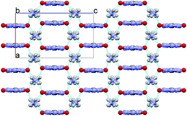 |
| | Fig. 6 The packing diagram of ABTOX viewed from the b-axis direction. The grey, white, red and blue balls represent C, H, O and N atoms, respectively. | |
Table 2 Hydrogen bond lengths (Å) and bond angles (°) for ABTOX
| D–H⋯A |
d(D–H), Å |
d(H⋯A), Å |
d(D⋯A), Å |
Angle(D–H⋯A), ° |
| N8–H8A⋯O1 |
0.818 |
2.324 |
3.074 |
152.57 |
| N8–H8B⋯O1 |
0.862 |
2.041 |
2.902 |
178.99 |
| N9–H9⋯O1 |
0.873 |
2.152 |
2.970 |
155.65 |
| N10–H10⋯O1 |
0.873 |
2.160 |
2.970 |
154.05 |
 |
| | Fig. 7 The hydrogen bonds of ABTOX. | |
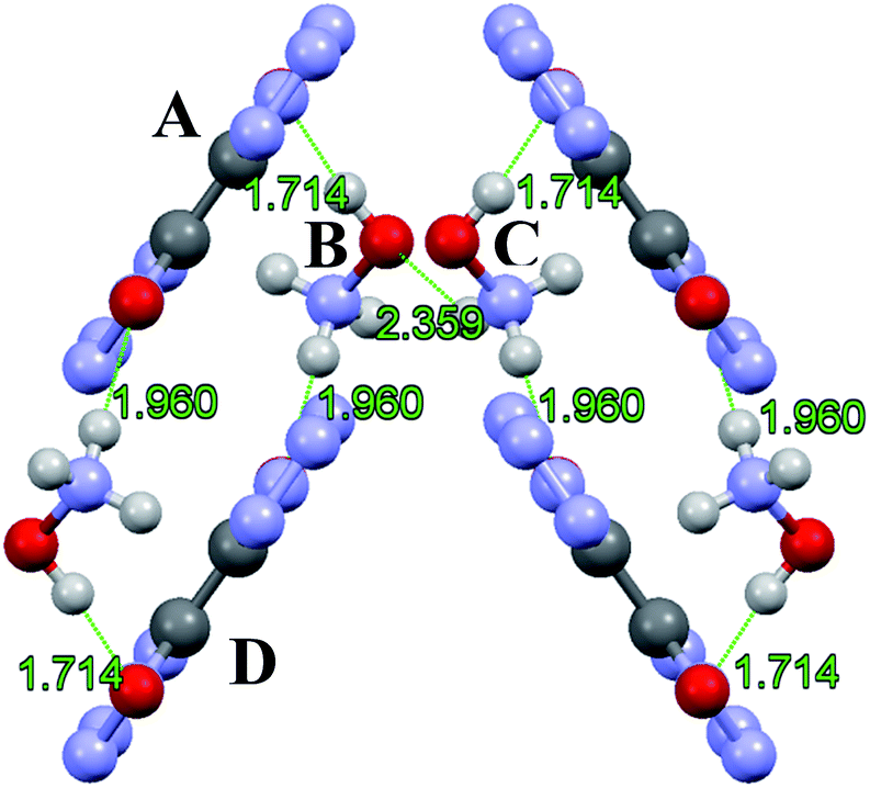
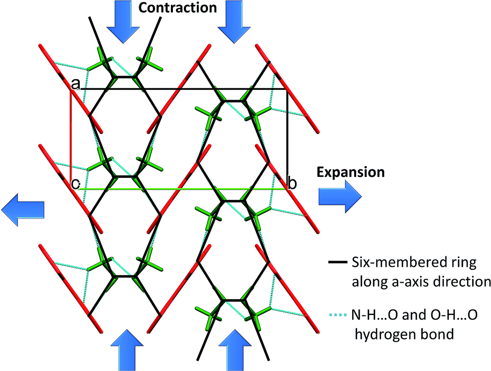
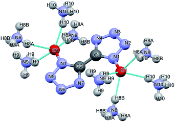
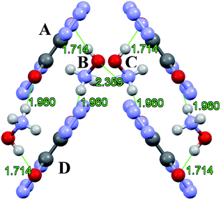
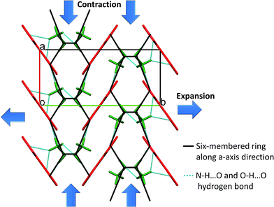
TKX-50 is monoclinic, has strong hydrogen bonding between the cations and anions, mainly through the H atom on (NH3OH)+ and the O atoms and N atoms on the bistetrazoles, and the minimum hydrogen bonding distance is 1.714 Å. The HBs of TKX-50 are shown in Fig. 8. The packing mode of the crystal cell under thermal expansion will be influenced by the strong hydrogen bonding. The packing diagram of TKX-50 along the a-axis direction is shown in Fig. 9. It is found that a six-membered ring unit is formed by strong hydrogen bonding and these units accumulate gradually along the a-axis direction. From the interactions between the cations and anions, the hydrogen bonding between A and B and B and D are stronger than the hydrogen bonding between B and C. Therefore, under thermal stimulation, the vibration of TKX-50 also increases. The weaker part of the six-membered ring structure is elongated first, which leads to the flattening of the six-membered ring and the a-axis direction of the crystal cell is contracted, thus the a-axis exhibits NTE. The constant expansion of the b-axis and sustained compression of the a-axis lead to a shortening of the distance between A and B and between B and D. As the temperature keeps rising and the distance is shortened to a certain extent, H-transfer is induced, in which the H atom of NH3OH+ transfers to the O atom of bistetrazole and NH2OH and 1H,1′H-5,5′-bistetrazole-1,1′-diol (BTO) are formed. However, NH2OH is very unstable at room temperature, and NH2OH continues to decompose and form NH3 and H2O, etc. at high temperatures. Meanwhile, A and D gradually become parallel to the b-axis due to the reduction of the resistance between A and D. NH3 then combines with BTO to form ABTOX.
 |
| | Fig. 8 The hydrogen bonds of TKX-50. | |
 |
| | Fig. 9 The packing diagram of TKX-50 (viewed from the a-axis direction). | |
3.4 The secondary decomposition of TKX-50
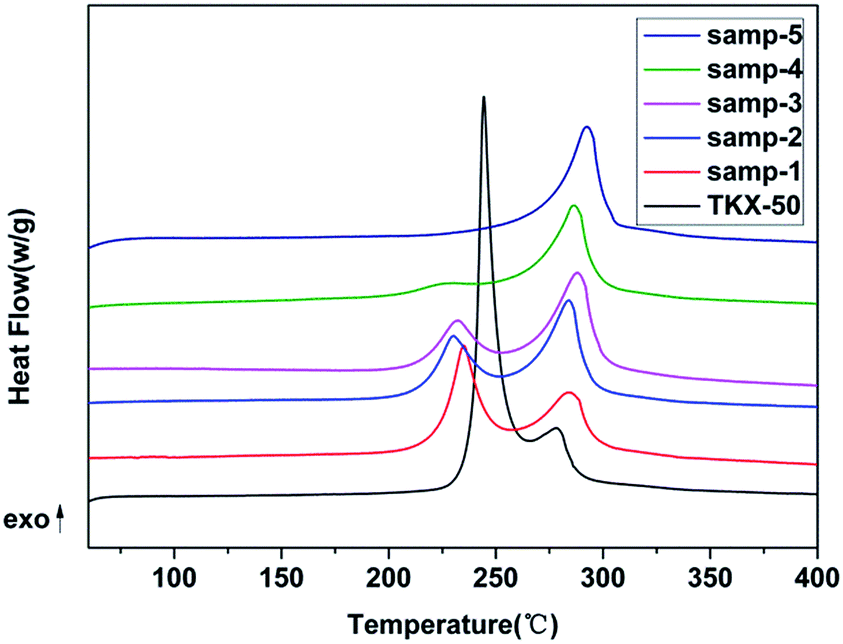
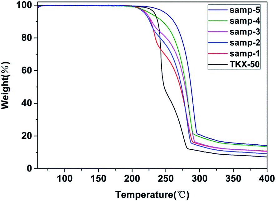
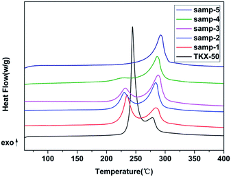
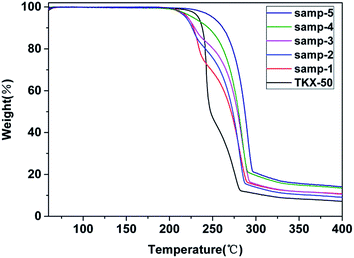
Thermogravimetric-differential scanning calorimetry (TG-DSC) was employed to analyse secondary decomposition of TKX-50. The obtained TG thermograms are shown in Fig. 10 and the DSC thermograms are shown in Fig. 11.
 |
| | Fig. 10 TG thermograms of TKX-50 and samples after primary decomposition. | |
 |
| | Fig. 11 DSC thermograms of TKX-50 and samples after primary decomposition. | |
From the TG-DSC curve of raw TKX-50, two exothermic decomposition peaks are obvious. The thermodynamic parameters are shown in Table 3. The enthalpy of the first decomposition process is much greater than that of the second process. The peak temperature of the first exothermic peak is 244 °C and the second is 278 °C. Compared with the TG-DSC curve of raw TKX-50, it is found that the enthalpy value of the first exothermic peak decreases with the increasing heat treatment temperature and that of the second peak increases. Moreover, the peak temperature of the samples after primary decomposition of raw TKX-50 is lower than that of TKX-50. The main intermediate product after primary thermal decomposition is stable.
Table 3 Thermodynamic parametersa
| Samples |
T1 (°C) |
T2 (°C) |
ΔH1 (J g−1) |
ΔH2 (J g−1) |
| Samp-1, samp-2, samp-3, samp-4 and samp-5 represent the materials after primary thermal decomposition under isothermal conditions at 190, 192, 194, 196 and 198 °C, respectively; T1: the peak temperature of primary decomposition; T2: the peak temperature of secondary decomposition; ΔH1: the enthalpy of primary decomposition; ΔH2: the enthalpy of secondary decomposition. |
| TKX-50 |
244.3 |
278.4 |
1564.0 |
370.1 |
| Samp-1 |
235.0 |
284.2 |
782.9 |
771.6 |
| Samp-2 |
230.3 |
284.0 |
517.9 |
859.0 |
| Samp-3 |
230.0 |
284.0 |
442.7 |
877.4 |
| Samp-4 |
230.0 |
286.3 |
250.8 |
911.4 |
| Samp-5 |
— |
292.3 |
— |
998.4 |
It is deduced that the decrease in enthalpy is caused by the fact that TKX-50 is decomposed slowly in the process of primary decomposition, accompanied by the release of energy. Moreover, the conversion degree is different due to the different isothermal temperature at the same time and the conversion degree of TKX-50 to the intermediate product is 24.30% at 190 °C and 100% at 198 °C (Fig. 3). Therefore, the enthalpy of the first decomposition gradually decreased with the increase in isothermal temperature. Meanwhile, it is deduced that the advanced peak temperature of the samples after heat treatment is caused by the fact that the primary and secondary thermal decompositions of TKX-50 are influenced by each other. Also, the integrity of the crystal structure is destroyed during primary decomposition which accelerates the thermal decomposition rate and increases the peak temperature of secondary decomposition.
3.5 The gaseous decomposition products and the thermal decomposition mechanism of TKX-50
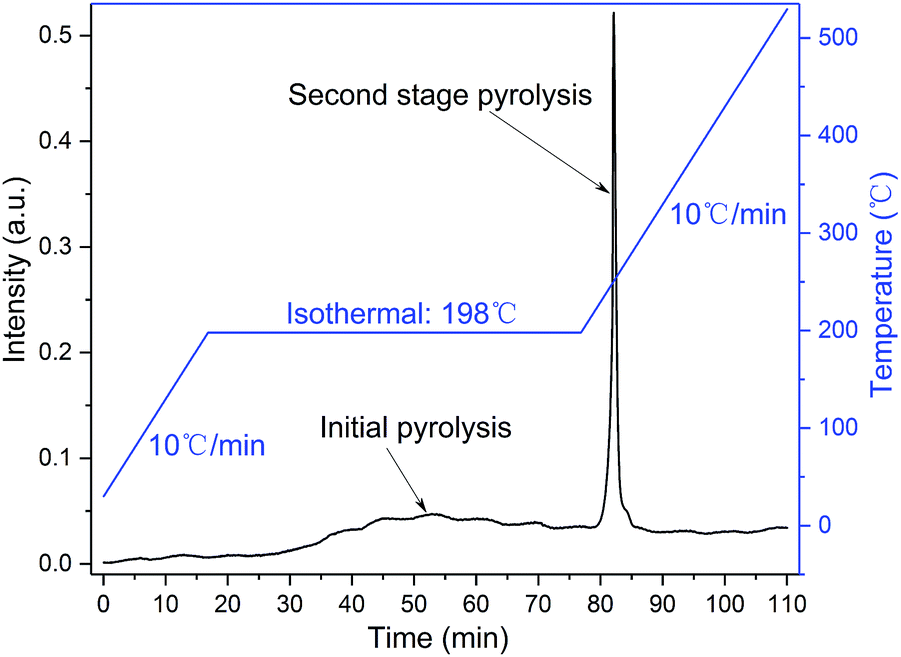
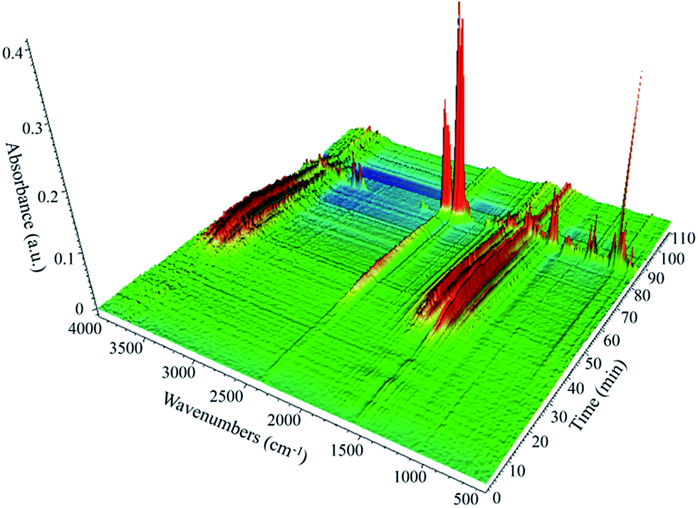
TG-FTIR technology was applied to analyse the gaseous decomposition products of each process. The FTIR signal spectrum and the corresponding temperature program are shown in Fig. 12 and the three-dimensional FTIR spectra of the TKX-50 thermal decomposition gas products are shown in Fig. 13. It is found that the primary decomposition of TKX-50 yields large amounts of H2O at 198 °C, which is confirmed by the characteristic peaks for water vapor in the infrared spectrum at 4000–3500 cm−1 and 2000–1500 cm−1. It is also consistent with the result that the liquid forms bubbles that emerge from the crystal as shown in Fig. 1. The FTIR spectra show that the primary decomposition is mainly the decomposition of NH3OH+ to form H2O, NH3, N2 and N2O, and that NH3 combines with BTO to form ABTOX, which is consistent with the previous analysis. In addition, when the temperature continues to rise, ABTOX mainly decomposes into N2O, CO2, N2, etc.
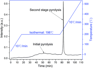 |
| | Fig. 12 The FTIR signal spectrum and corresponding temperature program (the blue line represents the temperature program and the black line represents the FTIR signal spectrum of the TKX-50 thermal decomposition gas products). | |
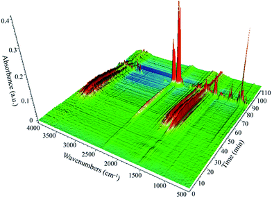 |
| | Fig. 13 The three-dimensional FTIR spectra of the TKX-50 thermal decomposition gas products. | |
The proposed thermal decomposition mechanism of TKX-50 is shown in Fig. 14. Under thermal stimulation, crystal expansion occurs first and is followed by H-transfer, which accelerates the primary decomposition of TKX-50. As the temperature increases, the primary decomposition becomes more intense, and ABTOX gradually forms by the combination of NH3 and BTO, accompanied by the generation of H2O, N2 and N2O. When the temperature continues to rise, ABTOX eventually breaks down into small molecular gaseous products such as N2O, CO2, N2, etc.
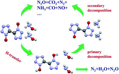 |
| | Fig. 14 The proposed thermal decomposition mechanism of TKX-50. | |
4. Conclusions
In this paper, the crystal structure transformation of TKX-50 during heat treatment was analysed by means of in situ XRD, TG-DSC and TG-FTIR. It was found that only anisotropic thermal expansion occurs from 30 °C to 175 °C, during which the a-axis and β angle exhibit NTE and the b-axis, c-axis and unit cell volume exhibit PTE, leading to a change of intermolecular force and the expansion and flipping of some molecules. In particular, the NTE of the a-axis results in a shorter distance between the cations and dianions, which induces hydrogen transfer, which then accelerates primary decomposition of TKX-50. With the increasing temperature primary decomposition occurred and the intermediate product ABTOX was formed, which was confirmed by single XRD, and we deduced the process from TKX-50 to ABTOX. The morphology change from thermal expansion to primary decomposition was obtained by HSM and the results are consistent with each process. When the temperature continues to rise to 270 °C, secondary decomposition occurrs. The gas products were also obtained by TG-FTIR and the decomposition mechanism was proposed. In short, TKX-50 has undergone thermal expansion, primary decomposition and secondary decomposition under heat stimulation. It can be concluded that energetic ionic salts often have multistep thermal decomposition processes because of their crystal structure. Just for this reason, it is very important to control the compatibility of materials with other materials in order to ensure they are suitable for a particular application and effectively avoid structural deterioration.
Conflicts of interest
There are no conflicts to declare.
Acknowledgements
This work was financially supported by the Natural Science Foundation of China (No. 11572295, 11372290 and 11472252).
References
- Y.-H. Joo and J. M. Shreeve, J. Am. Chem. Soc., 2010, 132(42), 15081–15090 CrossRef CAS PubMed.
- Y.-H. Joo and J. M. Shreeve, Angew. Chem., Int. Ed., 2010, 49, 7320–7323 CrossRef CAS PubMed.
- M. J. Crawford, T. M. Klapotke, F. A. Martin, C. M. Sabate and M. Rusan, Chem.–Eur. J., 2011, 17, 1683–1695 CrossRef CAS PubMed.
- T. M. Klapotke, P. Mayer, A. Schulz and J. J. Weigand, J. Am. Chem. Soc., 2005, 127, 2032–2033 CrossRef PubMed.
- T. M. Klapotke, C. M. Sabate and M. Rasp, J. Mater. Chem., 2009, 19, 2240–2252 RSC.
- H. X. Gao and J. M. Shreeve, Chem. Rev., 2011, 111, 7377–7436 CrossRef CAS PubMed.
- T. M. Klapotke and C. MiroSabate, Chem. Mater., 2008, 20, 3629–3637 CrossRef.
- A. Mehrkesh and A. T. Karunanithi, ACS Sustainable Chem. Eng., 2013, 1, 448–455 CrossRef CAS.
- T. M. Klapotke, K. Karaghiosoff, P. Mayer, A. Penger and J. M. Welch, Propellants, Explos., Pyrotech., 2006, 31, 188–195 CrossRef.
- M. von Denffer, T. M. Klapotke, G. Kramer, G. Spieß, J. M. Welch and G. Heeb, Propellants, Explos., Pyrotech., 2005, 30, 191–195 CrossRef CAS.
- Z. Zeng, H. X. Gao, B. Twamley and J. M. Shreeve, J. Mater. Chem., 2007, 17, 3819–3826 RSC.
- T. M. Klapotke and F. X. Steemann, Propellants, Explos., Pyrotech., 2010, 35, 114–129 CrossRef.
- P. He, J. G. Zhang, X. Yin, J. T. Wu, L. Wu, Z. N. Zhou and T. L. Zhang, Chem.–Eur. J., 2016, 22, 7670–7685 CrossRef CAS PubMed.
- C. F. Ye, J. C. Xiao, T. Brendan and J. M. Shreeve, Chem. Commun., 2005, 2750–2752 RSC.
- J. C. Galvez-Ruiz, G. Holl, K. Karaghiosoff, T. M. Klapotke, K. Loehnwitz, P. Mayer, H. Noeth, K. Polborn, C. J. Rohbogner, M. Suter and J. J. Weigand, J. Inorg. Chem., 2005, 44, 4237–4253 CrossRef CAS PubMed.
- R. S. Damse and A. K. Sikder, J. Hazard. Mater., 2009, 166, 967–971 CrossRef CAS PubMed.
- N. Fischer, T. M. Klapotke, M. Reymann and J. Stierstorfer, Eur. J. Inorg. Chem., 2013, 12, 2167–2180 CrossRef.
- N. Fischer, D. Fischer, T. M. Klapotke, D. G. Pierccey and J. Stierstorfer, J. Mater. Chem., 2012, 22, 20418–20422 RSC.
- J. L. Gottfried, T. M. Klapotke and T. G. Witkowski, Propellants, Explos., Pyrotech., 2017, 42, 353–359 CrossRef CAS.
- N. Fischer, T. M. Klapotke, S. M. Musanic, J. Stierstorfer and M. Suceska, New Trends Res. Energ. Mater., 2013, 16, 574–585 Search PubMed.
- H. F. Huang, Y. M. Shi and J. Yang, J. Therm. Anal. Calorim., 2015, 121, 705–709 CrossRef CAS.
- L. B. Xiao, F. Q. Zhao, Y. Luo, N. Li, H. X. Gao, Y. Q. Xue, Z. X. Cui and R. Z. Hu, J. Therm. Anal. Calorim., 2016, 123, 653–657 CrossRef CAS.
- H. Niu, S. S. Chen, S. H. Jin, L. J. Li, B. C. Jin, Z. M. Jiang, J. W. Ji and Q. H. Shu, J. Therm. Anal. Calorim., 2016, 126, 473–480 CrossRef CAS.
- Z. A. Dreger, C. J. Breshike and Y. M. Gupta, Chem. Phys. Lett., 2017, 679, 212–218 CrossRef CAS.
- Z. A. Dreger, A. I. Stash, Z. G. Yu, Y. S. Chen and Y. C. Tao, J. Phys. Chem. C, 2017, 121, 5761–5767 CAS.
- Q. An, W. G. Liu, W. A. Goddard and S. V. Zybin, J. Phys. Chem. C, 2015, 119, 2196–2207 CAS.
- L. Y. Meng, Z. P. Lu, X. F. Wei, X. G. Xue, Y. Ma, Q. Zeng, G. J. Fan, F. D. Nie and C. Y. Zhang, CrystEngComm, 2016, 18, 2258–2267 RSC.
- V. P. Sinditskii, S. A. Filatov, V. I. Kolesov, K. O. Kapranov, A. F. Asachenko, M. S. Nechaev, V. V. Lunin and N. I. Shishov, Thermochim. Acta, 2015, 614, 85–92 CrossRef CAS.
- N. V. Muravyev, K. A. Monogarov, A. F. Asachenko, M. S. Nechaev, I. V. Ananyev, I. V. Fomenkov, V. G. Kiselev and A. N. Pivkina, Phys. Chem. Chem. Phys., 2017, 19, 436–449 RSC.
- Z. P. Lu, X. G. Xue, L. Y. Meng, Q. Zeng, Y. Chi, G. J. Fan, H. Z. Li, Z. M. Zhang, F. D. Nie and C. Y. Zhang, J. Phys. Chem. C, 2017, 121, 8262–8271 CAS.
- C. Xue, J. Sun, B. Kang, Y. Liu and X. F. Liu, Propellants, Explos., Pyrotech., 2010, 35, 333–338 CrossRef CAS.
- Y. Liu, S. C. Li, Z. S. Wang, J. J. Xu, J. Sun and H. Huang, Cent. Eur. J. Energ. Mater., 2016, 13, 1023–1037 CrossRef.
- P. Kroll, M. Andrade, X. H. Yan, E. Ionescu, G. Miehe and R. Riedel, J. Phys. Chem. C, 2012, 116, 526–531 CAS.
Footnote |
| † Electronic supplementary information (ESI) available: IR, detailed structure description and CIFs. CCDC 1567754. For ESI and crystallographic data in CIF or other electronic format see DOI: 10.1039/c7ra08816g |
|
| This journal is © The Royal Society of Chemistry 2017 |
Click here to see how this site uses Cookies. View our privacy policy here. 
 Open Access Article
 This Open Access Article is licensed under a Creative Commons Attribution-Non Commercial 3.0 Unported Licence
 *b,
Shichun Lib,
Haobin Zhangb and
Xiong Cao*a
*b,
Shichun Lib,
Haobin Zhangb and
Xiong Cao*a