 Open Access Article
Creative Commons Attribution 3.0 Unported Licence
A hybrid electromagnetic and leaf-shaped polytetrafluoroethylene triboelectric with an arc-shaped brace structure for energy harvesting†
Run Huang a and
Jianxiong Zhu*b
aSchool of Materials Science and Engineering, Anhui University of Science & Technology, Huainan, 232001, China
bBeijing Institute of Nanoenergy & Nanosystems, Chinese Academy of Sciences, National Center for Nanoscience and Technology (NCNST), Beijing 100083, China. E-mail: danverzhu@gmail.com
First published on 25th October 2017
Abstract
We present a hybrid electromagnetic generator (EMG) and leaf-shaped polytetrafluoroethylene (PTFE) triboelectric nanogenerator (TENG) with an arc-shaped brace structure for mechanical energy harvesting. The pick-up coil is incorporated into a carbon black (CB) and silicone rubber mixture film at the bottom of the separation component as the EMG, and the TENG is carefully designed with two opposite arc-shaped braces for the contact and separation. It has been demonstrated that the leaf-shaped PTFE film could greatly enhance the collection efficiency of the mechanical energy due to both the leaf-shaped surface and the high voltage corona charge in the TENG. The EMG and TENG can achieve an instantaneous power output of 80 µW cm−2 and 675 µW cm−2 by calculation, respectively. Moreover, a random finger tap test revealed that a high electrical performance is achieved, with a voltage output of 0.25 V and 24 V from the EMG and TENG, respectively.
1. Introduction
The limited lifetimes and maintenance difficulties of batteries are large constraints for the rapid development of electronic devices towards advancing mankind. There are several potential methods which could be used to provide energy to electronic devices, such as piezoelectric, electrostatic, electromagnetic, and triboelectric methods.1–5 The principle of a triboelectric energy nanogenerator (TENG) is that when two materials are in contact and then separated, the alternating potential will drive electrons into the external load causing them to flow back and forth.6–9 Compared with piezoelectric and electrostatic harvesters, the advantage of using electromagnetic or triboelectric harvesters is that they have a simple structure with a high energy-conversion density output. In addition, TENGs can directly convert mechanical energy from wind, flowing water, and human motion into electricity on the basis of triboelectricity and the electrostatic induction effect.6–12 An electromagnetic generator (EMG) can produce power based on the motion of a coil in a magnetic field. Furthermore, the electromagnetic method has been demonstrated widely in our daily lives towards powering our electronic devices.13–16 For example, Lee et al. reported on non-resonant electromagnetic wideband energy harvesting from low frequency ambient vibration,15 however, the maximum power produced in their design was about 0.4 µW. Almasri et al. introduced impact oscillations for an electromagnetic power harvester using a nonlinear cantilever beam, and when tested it showed a power output of 85 µW was reached at 5 g for an external vibration of 30 Hz.16 In addition, due to the hot topic of motion energy harvesting, Li et al. summarized EMGs based on biomechanical energy harvesting from human motion.17Recently, hybrid nanogenerators combining several mechanisms have attracted increasing attention from researchers, such as using the hybrid piezoelectric, triboelectric, or electromagnetic principle to convert the mechanical energy into electricity.18–20 Wang et al. introduced a waterproof triboelectric–electromagnetic generator in a harsh environment which could harvest enough power to light a LED.18 Zhang et al. reported a hybrid piezoelectric and triboelectric mechanism for energy harvesting, however, the piezoelectric component is weaker than the triboelectric component, having a more limited voltage tolerance in the design.19 Zhu et al. introduced a coupling of the photoelectric and triboelectric effects for sensing and energy harvesting.20 Based on the trials of the different principles for energy harvesting, we have proposed a hybrid electromagnetic generator (EMG) and leaf-shaped polytetrafluoroethylene (PTFE) triboelectric nanogenerator (TENG) with an arc-shaped brace structure for energy harvesting. It has been demonstrated that the leaf-shaped PTFE film could greatly enhance the collection efficiency of the mechanical energy by high voltage corona charging, as well as for the leaf-shaped nanostructure in the TENG, and the EMG and TENG can achieve an instantaneous power output of 80 µW cm−2 and 675 µW cm−2, respectively.
2. Experimental
Fig. 1(a and b) depicts a 3D illustration illustrating the design of the prototype of the hybrid electromagnetic and leaf-shaped PTFE triboelectric energy harvester. It is a layered structure with two separation components. The bottom separation component contained an acrylic substrate, with dimensions of 2.5 cm × 2.5 cm × 2 mm, and was prepared by laser cutting. Fig. 1(c) shows a carbon black (CB) electrode, with dimensions of 2 cm × 2 cm × 2 mm, and the leaf-shaped PTFE film and a pick-up coil made up of 36 gauge copper wire were incorporated into the CB film, with an effective area of 78.5 mm2. It is noted that 5 mL of silicone rubber (Smooth-On Ecoflex 00-30) and 5 mL of carbon black powder (TIMCAL Super P LiCompany) were added into a cup and mixed with the aid of mechanical stirring for 30 min to prepare the CB and silicone rubber mixed film. The top separation component contained another acrylic substrate, with dimensions of 2.5 cm × 2.5 cm × 2 mm, a square permanent NdFeB magnet, with dimensions of 1 cm × 1 cm, and a piece of copper electrode. Then, a long piece of polyimide film, with dimensions of 10 cm × 2.5 cm × 0.125 mm, was prepared to attach the separation parts to form a pair of arc-shaped braces. Finally, lead wires were connected to each of the electrodes for conducting the measurements. The generated power was caused by the triboelectric effect from the contact between the CB electrode and the pick-up coil with relative motion in the magnetic field. During the electrical measurement, the bottom CB electrode and the top copper electrode were always connected to the positive and negative terminals, respectively, of an electrometer for data acquisition. It is noted that the leaf-shaped PTFE film was corona charged (using high voltage polarization apparatus, model ET-2673A) at room temperature for 5 min with a voltage of −6.05 kV before the final measurement.3. Results and discussion
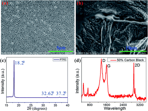
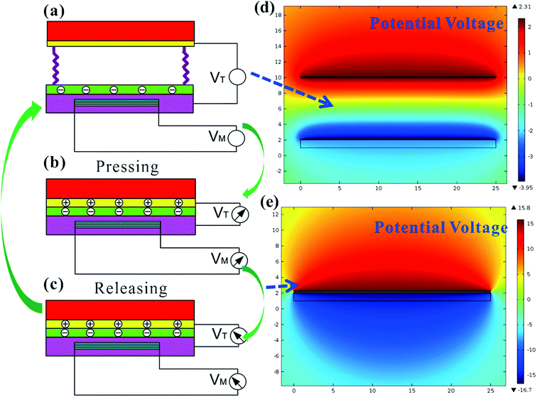
The surface morphology of the leaf-shaped PTFE electret film characterized by scanning electron microscopy (SEM Hitachi SU-8020) is shown in Fig. 2. Fig. 2(a) depicts the leaf-shaped PTFE film, and the detail of the prepared 50% CB mixed with silicone rubber can be easily observed in Fig. 2(b). The leaf-shaped PTFE film was characterized by X-ray diffraction (XRD, Panalytical, X’pert3 powder), and the XRD pattern is shown in Fig. 2(c). The XRD pattern shows an intense peak centered at 2θ = 18.2°, indicating long-range order in the (100) lattice plane and a typical PTFE crystalline structure. Also, the peak at 2θ = 32.62° was indexed to the (200) reflections which are associated with an in-plane structure. Raman spectroscopy (HORIBA Jobin Yvon LabRAM HR, France) of the CB and silicone rubber compound film showed three prominent peaks: the D peak at 1350 cm−1, induced by defects or bent sp2-carbon bonds, the first-order allowed G peak at 1580 cm−1, and the 2D peak at 2700 cm−1, which originates from second-order zone-boundary phonons.Fig. 3 schematically displays the working principle of the hybrid TENG and EMG. Fig. 3(a) shows the initial condition or the separation mode. If a motion is applied onto the top surface to bring the separation components into contact, the voltage on the electrode will dramatically increase due to the triboelectric effect between the leaf-shaped PTFE film and the copper electrode (see Fig. 3(b)). The magnetic field in the effective area of the pick-up coil will change dramatically due to the relative motion resulting in an instantaneous electrical output. If the force from the motion is released, the voltage on the electrode will dramatically decrease accordingly (see Fig. 3(c)). The potential voltage for the process of separation and with almost contact of the electret PTFE (see Fig. 3(d and e), respectively) has been obtained from a Finite Element Analysis (FEA) simulation performed by COMSOL Multiphysics. The EMG will have an electrical output due to the relative motion of the pick-up coil in the space of the electromagnetic field.
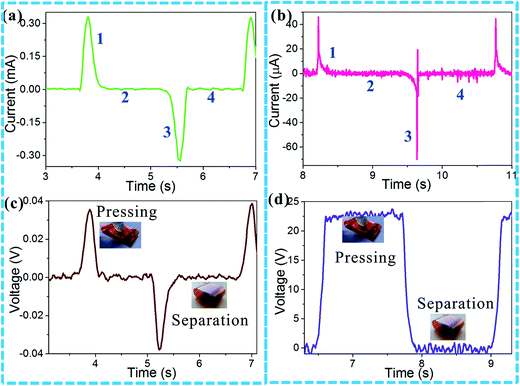
As can be seen in Fig. 4(a and b), the “starting” of the pressing process is defined with a number 1 and the “pressing pause” is defined with a number 2. The “pressing pause” means that the deformation is kept the same. Number 3 indicates the releasing of the pressing motion and number 4 defines a separation period. The electrons on the electrodes will always transfer to the load resistors due to the electrostatic equilibrium of the leaf-shaped PTFE electret film. Fig. 4(c and d) shows the obtained voltage curves for the pressing and separation states. By comparing the leaf-shaped PTFE in the hybrid system with corona charging (Fig. 4(d)) and without it (Fig. S1†), we found that the voltage value for the former prototype is about 2 times larger than that of the latter one.
When contact occurs between the copper electrode and the leaf-shaped PTFE electret film, the generated open-circuit voltage (Voc) of the triboelectric effect is given as
 | (1) |
 | (2) |
 | (3) |
 | (4) |
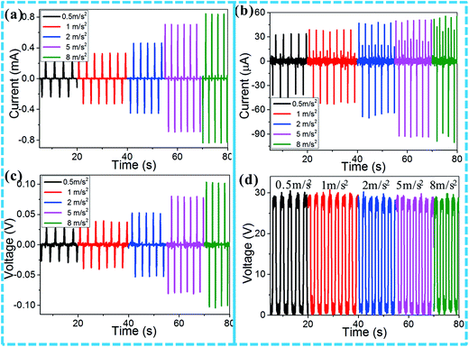
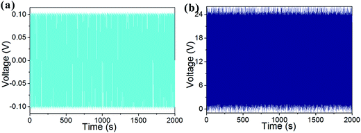
In order to control the pressing and separation state for the energy harvesting from the prototype, a linear motor (LinMot USA, Inc., Elkhorn, WI, USA) was used to perform a standard test for the electrical performance measurement, and the obtained results are shown in Fig. 5. It is noted that the linear motor was used to provide the periodic motion to the prototype. Also, a Keithley 6514 electrometer (Keithley Instruments, Inc, Ohio, USA) connected to a computer was used to measure the open-circuit voltage (Voc) and short-circuit current (Isc). The data was recorded using the LabVIEW program in real-time. As shown in Fig. 5(a and c), it is found that a higher acceleration results in a higher output voltage and current in the EMG. A short-circuit current of 0.8 mA and an open-circuit voltage of 0.1 V could be achieved for an acceleration of 8 m s−2. In addition, as shown in Fig. 5(b and d), at the same acceleration of 8 m s−2, an open-circuit voltage of 28 V and a short-circuit current of 90 µA could be obtained from the TENG component. The instantaneous power output of the EMG and TENG was calculated to be 80 µW cm−2 and 675 µW cm−2, respectively. It can be concluded that the TENG showed a better electrical performance than the EMG at this point. To clearly clarify the performance output of our work, we compared the obtained results with other works and the comparisons are listed in Table S1.† It is indicated that the prototype in the present work can produce a much higher voltage output with the same size than that in the other works. To demonstrate the reliability and durability of the EMG and TENG, the open-circuit voltage was measured for more than 2000 seconds. After this long-term and continuous operation, it is shown that there was no decline in the voltage output for both the EMG and TENG (see Fig. 6).
A random test using finger tapping is shown in Fig. 7, revealing the mechanical energy conversion electrical performance of the hybrid EMG and TENG. When a finger tap was applied to the prototype, an open-circuit voltage (Voc) was measured to demonstrate the instantaneous transfer of charge between the copper electrode and the CB electrode. The continuous tapping on the prototype is shown in Fig. 7(a and b), and the generated voltage from the EMG and the TENG is shown in Fig. 7(c) and (d), respectively. It is noted that even though the obtained voltage value from the EMG is much smaller than that from the TENG, the EMG has the advantage of having a much higher short-circuit current output (see Fig. 5(a and b)).
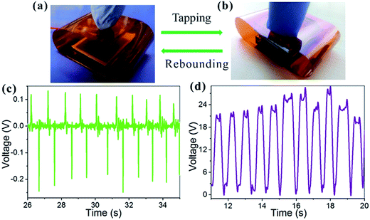 | ||
| Fig. 7 Finger tapping application: (a) a prototype before tapping; (b) a prototype during pressing; (c) the EMG, Voc with finger tapping; (d) the TENG, Voc with finger tapping. | ||
4. Conclusion
We have shown the feasibility of a hybrid EMG and leaf-shaped PTFE TENG with an arc-shaped brace structure for mechanical energy harvesting. It has been demonstrated that the leaf-shaped PTFE film could greatly enhance the collection efficiency of mechanical energy due to both the leaf-shaped surface and the high voltage corona charge in the TENG. The EMG and TENG achieved an instantaneous power output of 80 µW cm−2 and 675 µW cm−2 by calculation, respectively. Finally, a random finger tap test revealed that the hybrid EMG and TENG had a high electrical performance, with a respective voltage output of 0.25 V and 24 V.Conflicts of interest
There are no conflicts to declare.Acknowledgements
We appreciate the National Natural Science Foundation of China (Grant number 81501598), the Postdoctoral Science Foundation Funded Project of China (Grant number 2017M612052), the Introduced Doctor’s Startup Fund from the Anhui University of Science and Technology of China (Grant number ZY533), and the Shenzhen Science and Technology Innovation Fund of China (Grant number 20160825153358948) for financially supporting this work.References
- S. P. Beeby, M. J. Tudor and N. M. White, Meas. Sci. Technol., 2006, 17, R175–R195 CrossRef CAS.
- S. Li, Q. Zhong, J. Zhong, X. Cheng, B. Wang, B. Hu and J. Zhou, ACS Appl. Mater. Interfaces, 2015, 7, 14912–14916 CAS.
- L. B. Liu, Y. F. Cheng, L. L. Zhu, S. T. Lee, F. Liao and M. W. Shao, Sci. Rep., 2016, 6, 32943 CrossRef CAS PubMed.
- X. Q. Zhang, L. M. Wu and G. M. Sessler, AIP Adv., 2015, 5, 077185 CrossRef.
- J. W. Zhong, Q. Z. Zhong, G. J. Chen, B. Hu, S. Zhao, X. Li, N. Wu, W. B. Li, H. M. Yu and J. Zhou, Energy Environ. Sci., 2016, 9, 3085–3091 Search PubMed.
- D. Kim, I. W. Tcho, I. K. Jin, S. J. Park, S. B. Jeon, W. G. Kim, H. S. Cho, H. S. Lee, S. C. Jeoung and Y. K. Choi, Nano Energy, 2017, 35, 379–386 CrossRef CAS.
- Q. Leng, H. Guo, X. He, G. Liu, Y. Kang, C. Hu and Y. Xi, J. Mater. Chem. A, 2014, 2, 19427–19434 CAS.
- R. Hinchet, W. Seung and S. W. Kim, ChemSusChem, 2015, 8, 2327–2344 CrossRef CAS PubMed.
- W. Tang, J. Tian, Q. Zheng, L. Yan, J. Wang, Z. Li and Z. L. Wang, ACS Nano, 2015, 9, 7867–7873 CrossRef CAS PubMed.
- X. Y. Wei, G. Zhu and Z. L. Wang, Nano Energy, 2014, 10, 83–89 CrossRef CAS.
- Y. Yang, H. Zhang, X. Zhong, F. Yi, R. Yu, Y. Zhang and Z. L. Wang, ACS Appl. Mater. Interfaces, 2014, 6, 3680–3688 CAS.
- L. Zhang, L. Jin, B. B. Zhang, W. L. Deng, H. Pan, J. F. Tang, M. H. Zhu and W. Q. Yang, Nano Energy, 2015, 16, 516–523 CrossRef CAS.
- V. R. Challa, M. G. Prasad, Y. Shi and F. T. Fisher, Smart Mater. Struct., 2008, 17, 015035 CrossRef.
- O. Z. Olszewski, R. Houlihan, A. Mathewson and N. Jackson, J. Phys.: Conf. Ser., 2016, 757, 012039 CrossRef.
- B. Yang and C. Lee, Microsyst. Technol., 2010, 16, 961–966 CrossRef CAS.
- N. S. Yuksek, Z. C. Feng and M. Almasri, Appl. Phys. Lett., 2014, 105, 113902 CrossRef.
- J. P. Martin and Q. Li, Gait Posture, 2017, 52, 124–128 CrossRef PubMed.
- H. Y. Guo, Z. Wen, Y. L. Zi, M. H. Yeh, J. Wang, L. P. Zhu, C. G. Hu and Z. L. Wang, Adv. Energy Mater., 2016, 6, 1501593 CrossRef.
- M. D. Han, X. S. Zhang, W. Liu, X. M. Sun, X. H. Peng and H. X. Zhang, Sci. China: Technol. Sci., 2013, 56, 1835–1841 CrossRef CAS.
- L. Su, H. Y. Li, Y. Wang, S. Y. Kuang, Z. L. Wang and G. Zhu, Nano Energy, 2017, 31, 264–269 CrossRef CAS.
Footnote |
| † Electronic supplementary information (ESI) available. See DOI: 10.1039/c7ra08572a |
| This journal is © The Royal Society of Chemistry 2017 |


