 Open Access Article
Creative Commons Attribution 3.0 Unported Licence
Nucleation and growth of H blisters in stacking fault on B2–FeAl {100} planes
Guikai Zhang,
Feilong Yang,
Meijuan Hu,
Lang Liu,
Zhaoyi Luo and
Tao Tang *
*
China Academy of Engineering Physics, Institute of Materials, Jiangyou, 621908, China. E-mail: Tangtao@caep.cn
First published on 11th September 2017
Abstract
In the present work, the H accumulating behaviors at the stacking fault (SF) on {100} planes in B2–FeAl are studied by first-principles calculations. It is concluded that the SF on B2–FeAl {100} planes can trap H atoms, which serve as nucleation sites for H bubbles. When the areal density (the number of H atoms per the cross-sectional area of the SF) of the trapped H is as high as 5.9 × 10¹⁵ atoms per cm2, hydrogen recombines into molecules. With further increasing trapped H atoms, H bubbles grow gradually, yielding a hydrogen pressure of 3.4 GPa and strikingly elongating Al–Al bonds near the SF by 70% which implies the initiation of a crack, and eventually leads to a macroscopic fracture and crack of {100} type observed experimentally with the build-up of high pressures of hydrogen gases. This provides theoretical evidence for a HE mechanism of hydrogen blisters in iron aluminides.
1. Introduction
Iron aluminides have been widely studied as high-temperature structural materials due to their high mechanical strength, excellent corrosion/oxidation resistance and low cost. However, they tend to fail due to hydrogen embrittlement (HE), i.e. environmental embrittlement due to hydrogen generated from the reaction of aluminum in the alloy with water vapor, which has limited their use as engineering materials.1,2 Thus, the nature, cause, and control of HE of iron aluminides are of particular interest. This is a major concern in many industries including oil and gas, off-shore wind turbines, and hydrogen gas transport.Generally, the fracture surface of embrittled intermetallics exhibits cleavage facets of {100} type. Experiments have shown that the effect of hydrogen on ductility, crack initiation on {100}, and fractures along {111} and {100} planes, etc.3–7 Fracture in FeAl has been shown to propagate mainly along the {100} plane in air. In contrast, in vacuum, the fracture has been shown to occur along {111} for stoichiometric FeAl, and {100} for Fe–40Al, and Fe–35Al.
However, the reason for the weakness of iron aluminides along the {100} planes is not well understood and may be related to the type of bonding that exists across the {100} planes. Further on, these experimental results have been discussed with hydrogen-enhanced decohesion (HEDE), adsorption-induced dislocation emission (AIDE) and hydrogen-enhanced local plasticity (HELP) theories,8–10 to detail new surface formation, bond weakening, hydrogen-dislocation interaction as well as their consequences on HE. However, the atomic level mechanism underlying the formation cracks and fractures on {100} planes is still unclear.
Generally, H blisters (or bubbles), a typical structural damages, nucleate and grow bigger and eventually lead to the macroscopic failure observed experimentally. H blisters in Fe–Al intermetallics have been clearly observed under different experimental conditions.11,12 The high hydrogen pressure in H blister not only produced large internal stress, but also generated hydride ([AlH]) on the internal face of H blisters.12
Physically, formation of bubbles in metals involves two main steps: bubble nucleation and bubble growth. The defects in FeAl, such as vacancies, stacking faults, dislocations and grain boundaries, are believed to be the most possible nucleation sites for H bubbles.
Of these structural defects, monovacancies are mostly regarded as the origin of H bubble. By using first-principles calculations, we find that one Fe-vacancy in B2–FeAl can trap at least six H atoms to form VFeH6 complexes. The VFeH6 complexes prefer to bind along the 〈100〉 directions to form V2FeH12 〈100〉 complexes, with H2 molecules formation.13 These results may be closely associated with the fracture and crack along {100} planes observed in HE experiments of iron aluminides. However, H bubbles inside the Fe disvacancy are hard to grow up. Thus, we propose a mechanism of isotropic hydrogenated vacancy-clusters induced HE: hydrogen addition-induced isotropic V2FeH12 〈100〉 clusters of line and planar shapes are embryos for the formation of the crack and H2 bubbles. This may grow bigger as a function of H concentration and eventually lead to the macroscopic failure observed experimentally.
Furthermore, there are, in a rough classification, four kinds of vacancy-cluster product, i.e. 〈100〉 dislocation, 〈111〉 superlattice dislocation, antiphase boundaries on {111} planes and stacking fault (SF) on {001} planes. The SFs on {001} planes have been observed in Fe–35A114–16 and Fe–37Al–2Ni.17 Providing more space for H atoms to accommodate to form H blistering, the SFs, where the interactions of Al–Al and Fe–Fe are weak with respect to that in a prefect region, may act as nucleation and growth sites of H bubbles. Unfortunately, no clear (quantitative) characterization has been provided on such defects states and their interaction with hydrogen.
In present work, the H accumulating behaviors at the SFs on B2–FeAl {100} plane are explored by first-principles calculations. The results predict that the stacking faults can trap H atoms, serving as nucleation sites of H bubbles. When the areal density of the trapped H is up to 5.9 × 10¹⁵ atoms per cm2, H2 molecules are observed. With further increasing the trapped H atoms, H bubbles grow up gradually and may eventually lead to the macroscopic failure observed experimentally.
2. Computational method and model
We utilize DMol3 (ref. 18) program package in Materials Studio of Accelrys Inc to carry out first principles total energy calculations. Previous DFT–GGA calculations found a FM (ferromagnetic) state in FeAl nearly degenerate with an AFM (antiferromagnetic) state.19 However, experiments found no magnetism in stoichiometric FeAl,20 thus, we do not allow for magnetism to develop in B2–FeAl. Spin polarized calculations are performed by using GGA exchange correlation functional of Perdew and Wang (PW91)21 and double numerical quality basis set with polarization functions (DNP)22 and semi-core pseudopotential23 with a convergence tolerance of energy of 2.7 × 10⁻⁴ eV, a maximum displacement of 0.05 Å, a real-space cutoff of 5.3 Å, and without any symmetry constraints. We obtain a lattice constant of a = 2.888 Å for B2–FeAl, which agrees reasonably well with values of previous DFT–GGA calculations (a = 2.875 Å (ref. 24 and 25)) and the experiment (a = 2.909 Å (ref. 26)).To mimic SFs on {100} planes in B2–FeAl ({001}SF), one Fe atomic layer is removed from the perfect stacking sequence along 〈100〉 directions. Our calculations only address to the Fe atomic layer because VFe is more favorable vacancy in bulk FeAl,27 and Fe vacancies prefer to bind along the 〈100〉 direction, forming line clusters along the 〈110〉 directions and tabular ones along {110} or {100} planes.16 In chosen structural model of the {100} SF, the cell size along c direction should be large enough, so as to neglect the interaction between the SF and its images. For this purpose, we evaluate the Al–Al and Fe–Fe bond lengths nearby SF (the distance of head-on position atoms at the SF) with different cell size along c direction. Fig. 1 displays the averaged Al–Al and Fe–Fe bond lengths at the {100} SF as a function of the number of atomic layers along c. It is shown obviously that the Al–Al and Fe–Fe bond lengths at the SF are converged when the atomic layer along c reaches 17, indicating that the interaction between the SF and its image is slight. Thus we choose a supercell of 3 × 3 × 10 consisting 171 atoms and 21 atomic layers, to investigate the nucleation and growth of H bubbles in the SF on {100} planes of FeAl. It is found that the averaged bond length of Al–Al at the SF without H atom is about 2.754 Å, being short by about 5% with respect to that (2.892 Å) of the perfect FeAl bulk.
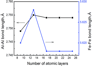 | ||
| Fig. 1 The averaged Al–Al and Fe–Fe bond lengths at {100} SF of B2–FeAl as a function of the number of atomic layers along c. | ||
The lattice parameter is fixed with atomic position relaxation during the calculation of H behaviors. Migration barriers for point defects are calculated by complete linear synchronous transit/quadratic synchronous transit (LST/QST) method using ten images.
3. Results and discussion
3.1. H trapping into FeAl {100} SF
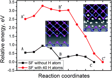
In bulk FeAl, the tetrahedral interstitial site consists of two Fe atoms and two Al atoms (Tet2Fe–2Al). There are two octahedral interstitial sites: the Oct2Fe–4Al site involves two axial Fe atoms and four equatorial Al, and the Oct2Al–4Fe site involves two axial Al atoms with four equatorial Fe. The H at Oct2Fe–4Al site is found to be energetically (0.02–0.03 eV) more stable than the Tet2Fe–2Al H, coinciding with previous calculations.13,25 The absorption energy of a H atom at the SF is lower by 0.40 eV than that of the Oct2Fe–4Al H far away from the SF. This signifies that H atoms trapped into the SF is thermodynamically feasible.Furthermore, the diffusion paths and the corresponding energy profile for a H atom from the next Oct2Fe–4Al (site A) to the SF (site C) are shown in Fig. 2. H migration into the SF has a barrier of 0.30 eV along path site B → site C, and is exothermic by −0.20 eV. Away from the SF, H jumps from an Oct2Fe–4Al site to an adjacent one (path Oct2Fe–4Al → Oct2Fe–4Al) by passing through a Fe–Al–Al triangle, with a barrier of 0.27 eV. Such barrier is in agreement with the H-diffusion barrier of 0.26 eV in bulk FeAl by previous calculation,25 whereas respectively lower and higher than the experimental barriers of H diffusivity in Fe3Al (0.42 eV)28 and Fe–40Al (0.22 eV).29 These low energies indicate that H atoms nearby the SF can easily diffuse into the SF at room temperature.
We further explore the diffusion behavior of an additional H atom from the OIS to the SF with H atoms accumulating. The energy profile for diffusion of the additional H atom between the Oct2Fe–4Al (site A′) and the SF with 40 H atoms, is plotted in Fig. 2. As can be seen from Fig. 2, barrier of the path site B′ → site C′ for the additional H atom decreases to be 0.04 eV. The exothermic energy of −3.0 shows that such path is thermodynamically favorable. On the contrary, the barrier for the H migrating away from the SF reaches up to 3.04 eV, implying that it is much more difficult for H atoms to escape when they are trapped into the SF. Therefore, the SFs on FeAl {100} planes are beneficial to H atoms accumulating.
3.2 Formation of H bubble at FeAl {100} SF
From the above results of H trapping into the FeAl {100} SF, we see that H atoms have large possibility gathering in the SF through diffusion. Nevertheless, accumulating H atoms in the SF should weaken the interaction of Al–Al and Fe–Fe at the stacking fault, and further cause H blistering at this defect. To check the possibility for H bubbles growth, we then discuss the accommodating capacity and the changes of the local structure of the SF with different H atoms.The binding energy for H atoms at the SF is defined as:30
| Eb = mESF + HOIS − ESF + mH − (m − 1)ESF, |
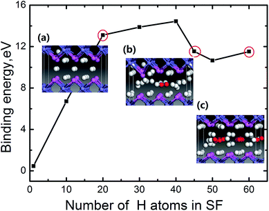
According to this definition, the dependence of the binding energy on the number of the H atoms trapped at the SF is plotted in Fig. 3. For each case with a certain number of H, different configurations for H atoms locating in the SF are observed. We can see for m < 40, the binding energy increases with increasing the number of H atoms. When the accumulating H atoms at the SF reach 45, an inflexion point appears in the binding energy curve. Careful examination of the atomic structure of the system (the bond length of Al–Al, Al–H and H–H) reveals that such inflexion point corresponds to the formation of H2 molecule for m = 45 (the related areal density is 5.9 × 10¹⁵ H atoms per cm−2, which is calculated by m/S, here S is the cross-sectional area of the SF). To clearly depict the formation of H2 molecule, the side view of the local structure of the SF containing 20 H (Fig. 3a) and 45 H (Fig. 3b) atoms are displayed in the insets of Fig. 3, in which the red balls refer to H2 molecules, with the H–H bond of 0.78 Å that is in agreement with the DFT optimized gas-phase bond length of H2. Thus a H2 molecule is observed in the SF for m = 45. We thus conclude that H2 molecules form, when the number of the trapped H atoms reaches about 45. Furthermore, as the number of the H atoms gathering in the SF increases, more H2 molecules present in the center of the SF. When the number of the gathering H atoms reaches up to 60, nine H2 molecules form in the SF as shown in the inset geometry in Fig. 3c.
To roughly estimate the H pressure, Pv, of the FeAl {100} SF with 60 H atoms, we employ the ideal gas state equation Pv = nRT/Vv, taking the temperature as being 300 K and the volume of the SF as  , where a is the metal lattice constant, and n is the mole of hydrogen at the SF. According to this estimation, the H pressure inside the SF is as high as 3.4 GPa. Such high pressure is more than sufficient to continue crack and fracture growth on the {100} planes. This is a strong support for the classical interpretation that the crack propagation is driven by build up of high pressure of hydrogen gases.31 As well, the high hydrogen pressure can help the hydride generating on the internal face of hydrogen blister.
3.3. Atom and electronic structure of FeAl {100} SF with H atoms
Basically, the accumulating H atoms have significant influence on the local structure of the FeAl {100} SF, which is reflected in the changes of the averaged bond length of Al–Al nearby the SF. Therefore, Fig. 4 displays the averaged bond length of Al–Al of the FeAl {100} SF as the function of the number of H atoms. As the number of H atoms in the SF increases, the average bond length of Al–Al increases slowly, featuring a linear trend almost. However, when the number of accumulating H atoms is more than 40, the average bond length of Al–Al increases abruptly. For the SF containing 40 H atoms, the averaged Al–Al bond length is elongated to be about 3.465 Å. When the number of the accumulating H at the SF is up to 50, the averaged Al–Al bond length reaches to be 4.168 Å. For the SF containing 60 H atoms, the averaged Al–Al bond length increases to be 4.680 Å, being larger by 70%. The average bond length of Fe–Fe increases slowly from 5.618 Å, and to be 7.360 Å, being larger by 35%, when the number of the accumulating H at the SF is up to 60 (Fig. 4). Such strikingly elongated Al–Al bond implys that many Al–Al bonds of the SF are broken, and the cavity presents in local structure of the SF. This may lead to initiation of crack and fracture in the {100} planes.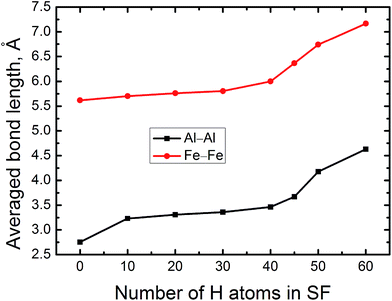 | ||
| Fig. 4 The averaged Al–Al and Fe–Fe bond lengths of FeAl {100} SF as a function of the number of the trapped H atoms. | ||
Compared to the strikingly elongated Al–Al bond, The Al–H bond length changes slightly, being about 1.61 Å with ±0.06 Å for different H capacity, and the Fe–H bond is about 1.55 Å with ±0.05 Å.
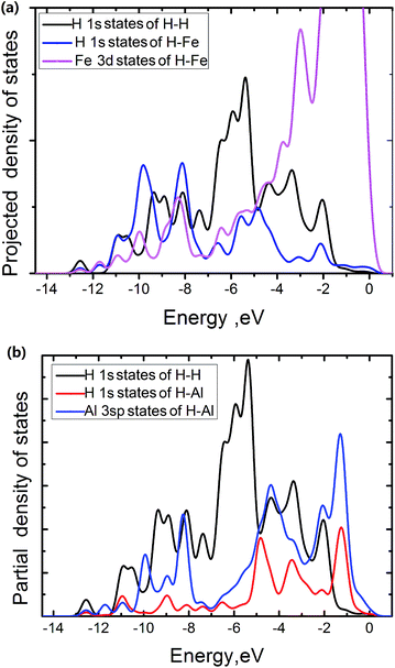
The electronic density of states is projected onto selected atoms to determine bonding character. From projected density of states (PDOS) of the Fe atoms at the edge of the FeAl {100} SF with 50 atoms, the H atom near the edge of the SF and the H atoms of H2 molecule in the center region of the SF (Fig. 5a), it is interesting to see that states of the H and Fe atoms overlap in range from −11.4 to −7.2 eV and −6.2 to 0.5 eV respectively. This suggests that the H interaction with Fe atoms involves the overlap between Fe 3d and H 1s states. The pronounced H 1s-sates of the Fe–H bond mainly peak from −11.4 to −7.2 eV. In contrast, the pronounced H 1s-sates of the H2 molecule in the center region of the SF mainly peak from −7.1 to −5.0 eV, and the Fe 3d sates of mainly peak from −5.0 to 0.5 eV. This shows that the H atoms of the H2 molecules have little interaction with the Fe atoms. The overlap states of the H near the SF and the Al atoms at the edge of the SF from −11.4 to −7.8 eV and −5.1 to −1.7 eV are observed respectively (Fig. 5b), showing that the H interaction with Al atoms involves the overlap between Al 3sp and H 1s states, with the pronounced H 1s-sates peaking from −5.1 to −1.7 eV. However, the pronounced H 1s-sates of H2 molecules peak from −7.1 to −5.0 eV, and the Al 3sp sates of mainly peak from −7.0 to 0.5 eV. This also shows that the H atoms of the H2 molecules have little interaction with the Al atoms at the edge of the SF.
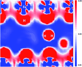
As shown in Fig. 6, the flatten electron clouds of the negatively charged H are indicative of electron–electron repulsion between the hydrogen atoms, whereas it is observed from Fig. 5 that the metal–H hybridization of Fe–H and Al–H prevails. Consequently, the competition between metal–H hybridization and coulombic repulsion leads to the formation of the H2 molecule in the FeAl {100} SF.
4. Conclusions
The H accumulating behaviors at the SF on {100} planes in B2–FeAl are explored by first-principles calculations, and we propose a possible formation mechanism for H blisters in the FeAl observed in experiments. The SFs on B2–FeAl {100} planes serve as trapping center to attract the H atoms nearby, being the nucleation site for H blisters. When the areal density of H atoms in the SF reaches to be 5.9 × 10¹⁵ atoms per cm2, H2 molecules are formed. With further increasing the trapped H atoms, H bubbles grow up gradually, not only yielding a large internal gas pressure of 3.4 GPa, but also strikingly elongating the Al–Al bonds near SF. This imply that many Al–Al bonds in SF are broken, and eventually lead to the macroscopic fracture and crack observed of {100} type experimentally. The competition between metal–H hybridization and coulombic repulsion leads to the formation of the H2 molecule in the FeAl {100} SF.Conflicts of interest
There are no conflicts to declare.Acknowledgements
We acknowledge financial supports from the National Natural Science Foundation (No. 21471137) and National Magnetic Confinement Fusion Science Program (No. 2013GB110006, 2014GB110006) of China. The authors also thank the computing resource provided by National Supercomputing Center in Shenzhen.Notes and references
- C. T. Liu, E. H. Lee and C. G. Mckamey, Scr. Metall. Mater., 1989, 23(6), 875 CrossRef CAS.
- C. G. Mckamey, J. H. Devan, P. F. Tortorelli and V. K. Sikka, J. Mater. Res., 1991, 6(8), 1779 CrossRef CAS.
- M. Nathal and C. Liu, Intermetallics, 1995, 3, 77 CrossRef CAS.
- P. Munroe and I. Baker, Acta Metall. Mater., 1991, 39, 1011 CrossRef CAS.
- R. Lynch, K. Gee and L. Held, Scr. Metall. Mater., 1994, 30, 945 CrossRef CAS.
- M. Wittmann, D. Wu, I. Baker, E. George and L. Heatherly, Mater. Sci. Eng., A, 2001, 319, 352 CrossRef.
- H. Saka and T. Ishizaki, Philos. Mag. A, 1996, 73, 1173 CAS.
- R. Oriani and P. Josephic, Acta Metall., 1979, 27, 997 CrossRef CAS.
- S. Lynch, Scr. Mater., 2009, 61, 331 CrossRef CAS.
- P. Ferreira, I. Robertson and H. Birnbaum, Acta Mater., 1999, 47, 2991 CrossRef CAS.
- P. D. White, S. A. Barter and N. Medhekar, Eng. Fract. Mech., 2016, 161, 40 CrossRef.
- V. S. Rao, Mater. Res. Bull., 2004, 39(2), 169 CrossRef CAS.
- G. Zhang, G. Huang, M. Hu, F. Yang, L. Liu, J. Konys and T. Tang, RSC Adv., 2017, 7, 11094 RSC.
- Z. Y. Song, H. Hashimoto and C. T. Chou, Philos. Mag. A, 1991, 64(2), 333 CrossRef CAS.
- Z. Y. Song, M. Hida, A. Sakakibara and Y. Takemoto, Scr. Mater., 1997, 37(11), 1617 CrossRef CAS.
- K. Yoshimi, S. Hanada, T. Onuma and M. H. Yoo, Philos. Mag. A, 1996, 73(2), 443 CAS.
- I. Baker and D. Gaydosh, Phys. Status Solidi A, 1986, 96(1), 185 CrossRef CAS.
- B. Delley, J. Chem. Phys., 2000, 113, 7756 CrossRef CAS.
- D. E. Jiang and E. A. Carter, J. Phys. Chem. B, 2005, 109, 20469 CrossRef CAS PubMed.
- J. Bogner, W. Steiner, M. Reissner, P. Mohn, P. Blaha, K. Schwarz, R. Krachler, H. Isper and B. Sepiol, Phys. Rev. B, 1998, 58, 14922 CrossRef CAS.
- J. A. White and D. M. Bird, Phys. Rev. B, 1994, 50, 4954 CrossRef CAS.
- B. Delley, J. Chem. Phys., 1990, 92, 508 CrossRef CAS.
- B. Delley, Phys. Rev. B, 2002, 66, 155125 CrossRef.
- C. L. Fu and G. S Painter, J. Mater. Res., 1991, 6, 719 CrossRef CAS.
- F. J. Donald and A. E. Carter, Acta Mater., 2010, 58, 638 CrossRef.
- M. Kogachi, T. Haraguchi and S. M. Kin, Intermetallics, 1998, 6, 499 CrossRef CAS.
- R. Besson, A. Legris and J. Morillo, Phys. Rev. B, 2006, 74, 094103 CrossRef.
- X. Cheng and X. Wang, Scr. Mater., 1998, 8, 1505 CrossRef.
- M. Kupka and K. Stepień, Corros. Sci., 2009, 51, 699 CrossRef CAS.
- K. Ohsawa, J. Goto, M. Yamakami, M. Yamaguchi and M. Yagi, Phys. Rev. B, 2010, 82, 184117 CrossRef.
- G. Chen, Y. Zhang and Y. Han, Intermetallic Compound Structural Materials, National Defense Industry Press, China, Beijing, 2001 Search PubMed.
| This journal is © The Royal Society of Chemistry 2017 |

