
 Open Access Article
 This Open Access Article is licensed under a Creative Commons Attribution-Non Commercial 3.0 Unported Licence
Toxicity analysis of poly(sodium-4-styrenesulfonate) coated graphene on HMEC-1 cells under dynamic conditions mimicking blood flow†
You-Long Chena,
Ju-Yun Chianga,
Hung-Tao Choua,
Chien-Yu Fub,
Ying-Chieh Chen *a,
Chi-Young Leea,
Nyan-Hwa Tai*a and
Hwan-You Chang*b
*a,
Chi-Young Leea,
Nyan-Hwa Tai*a and
Hwan-You Chang*b
aDepartment of Materials Science and Engineering, National Tsing Hua University, Hsin-chu, Taiwan 30013. E-mail: nhtai@mx.nthu.edu.tw; yisschen@mx.nthu.edu.tw; Tel: +886 3 5715131 ext. 72763 Tel: +886 3 5742568
bDepartment of Medical Science, National Tsing Hua University, Hsin-chu, Taiwan 30013. E-mail: hychang@mx.nthu.edu.tw; Tel: +886 3 5742910
First published on 8th November 2017
Abstract
Graphene has been proven to have great potential in medical applications. The goal of this study is to evaluate the toxicity of graphene on human microvascular endothelial cells (HMEC-1) under flowing conditions mimicking blood circulation. Graphene was prepared by the electrochemical exfoliation method and conjugated with poly(sodium-4-styrenesulfonate) (PSS) to improve its hydrophilicity and dispersion behavior. Under static cell growth conditions, 80 mg ml−1 of graphene reduced cell viability to 60% of the control. Graphene was observed to aggregate on the cell surface by interacting with filopodia. In contrast, graphene applied to cells under flowing conditions showed no significant negative influence on the cells regardless of graphene concentration, incubation time, and the exerted shear force. Graphene also showed lower toxicity towards cells in a flowing culture than multi-walled carbon nanotubes (MWCNTs) and carbon black. Together, these results suggest that the prolonged interaction of graphene with the cell surface is critical in causing cell damage. The lower circulatory toxicity of graphene compared to MWCNTs and carbon black also suggests that graphene is more suitable for use in drug delivery systems.
1. Introduction
Nanotechnology is a rapidly developing research field that provides new opportunities, which are likely to revolutionize the future of medicine. The application of nanomaterials in biomedicine is particularly exciting due to their ability to pass through biological barriers, making them attractive substances for use in potential treatments. Taking cancer treatment as an example, nanomaterials may be developed into platforms to assist in the processes of diagnosis, surgery, radiation therapy, and chemotherapy.1Graphene is an atomic layer of carbons that are arranged in a hexagonal structure2 and has drawn considerable attention for its potential applications in biomedicine. Graphene has a high specific surface area, extraordinary thermal conductivity, high electron mobility, strong mechanical strength,3–6 and can be modified with various functional groups (epoxide, hydroxyl, and carboxyl groups) on its large planar surface area for the efficient loading of drug molecules via π–π stacking. Moreover, it has been demonstrated that graphene of a controllable size that possesses excellent photothermal/photodynamic properties could cross the cell membrane through active transport in different cell types, making graphene an ideal carrier for drug targeting,7–11 medical imaging,7,11,12 photothermal therapy,11,13–15 and accelerating stem cell differentiation.16
Prior to its use in clinical applications, it is necessary to determine whether graphene causes cytotoxicity. Some articles have been published showing the cytotoxicity of graphene in vitro17–21 and in vivo.22,23,28 These findings demonstrated the existence of dose- and size-dependent cytotoxicity both in vitro and in vivo; however, some researchers do not agree with these findings. The controversial issue of cytotoxicity and biocompatibility must be resolved in order to apply this nanomaterial in clinical applications.
Unfortunately, the in vitro models for assessing the cytotoxicity of graphene, such as cultured monolayer cells, may not correlate well with the complex and dynamic nature of the in vivo environment. Recent advances in microfluidic systems, which may provide an environment mimicking that in vivo, can facilitate more accurate drug testing24,25 and thus can be used to further understand graphene cytotoxicity. The goal of this study is to investigate how graphene interacts with endothelial cells in circulation. It is believed that more relevant information concerning the behavior of graphene in the human body could be obtained by using a microfluidic chip to grow cells under conditions mimicking blood flow.
2. Experimental
2.1 PSS–graphene preparation and characterization
The electrochemical exfoliation method was used to produce PSS–graphene. First, polystyrene sulfonate (PSS) was dispersed in water by sonication for 30 min and used as an electrolyte in the following electrochemical exfoliation processes. Two graphite rods were used as electrodes in a vertical orientation and were separated by 5 cm in a 0.001 M PSS solution. A direct current voltage of 5 V was used during the electrolysis process and carbon flakes gradually exfoliated from the anode, resulting in a suspension containing PSS–graphene after 6 h of sonication. Subsequently, the uniform suspension was vacuum filtered through both a 1 μm and a 220 nm porous membrane to remove residual PSS and to obtain filtrate PSS–graphene with expected sizes.To prepare PSS–f-MWCNTs and PSS–f-carbon black, both MWCNTs and carbon black were adopted as starting materials and were functionalized before conjugating PSS. MWCNTs with a weight of 0.2 g were added to a 100 ml mixture of sulfuric acid and nitric acid (3![[thin space (1/6-em)]](https://www.rsc.org/images/entities/char_2009.gif) :1 by volume) and subjected to stirring in a water bath at 80 °C for 4 h. Subsequently, the f-MWCNTs were washed to neutrality using deionized water and sonicated with PSS solution to ensure that f-MWCTs were successfully conjugated to PSS (PSS–f-MWCNTs or PSS–MWCNT). Finally, centrifugation was used to remove the excess PSS. The aforementioned process was also applied to prepared PSS–f-carbon black (PSS–carbon black).
:1 by volume) and subjected to stirring in a water bath at 80 °C for 4 h. Subsequently, the f-MWCNTs were washed to neutrality using deionized water and sonicated with PSS solution to ensure that f-MWCTs were successfully conjugated to PSS (PSS–f-MWCNTs or PSS–MWCNT). Finally, centrifugation was used to remove the excess PSS. The aforementioned process was also applied to prepared PSS–f-carbon black (PSS–carbon black).
To characterize the micromorphology after functionalization of PSS, a field emission scanning electron microscope (FE-SEM; JEOL JSM-6500F) and an atomic force microscope (AFM; Veeco Nanoscope 3100) were used. Raman spectroscopy (Jobin Yvon LabRam HR-800/632.8 nm He–Ne laser) was used to analyze the quality of the material, and Fourier transform infrared (FTIR) spectroscopy (Perkin-Elmer Spectrum RX) was used to examine the presence of functional groups on the graphene surface. The lateral sizes and dispersion behavior of the PSS–graphene were analyzed using the Zeta-sizer (Malvern) equipped with a dynamic light scattering system.
2.2 Microfluidic chip fabrication
The channel in the microfluidic chip was 1 mm long, 200 μm wide, and 500 μm high. The microfluidic chip was fabricated with poly(dimethylsiloxane) (PDMS; Sylgard 184, Dow Corning) and bonded to a glass slide. The PDMS base was mixed with a curing agent in a 10:1 ratio, casted on a self-designed mold, degassed in a vacuum, and cured at 80 °C for 2 h. The glass slide was washed using acetone, alcohol, and double distilled water. The PDMS layer was permanently bonded onto a glass slide using oxygen plasma treatment at 70 W for 10 s. The chip was then heated to 150 °C for 20 min to enhance the bonding between PDMS and the glass slide. For the following cell culture experiments, the microfluidic chip was sterilized by rinsing sequentially with 75% and 95% ethanol and placed under UV light for 3 h to ensure sterility.
2.3 Cell culture
The human microvascular endothelial cell line (HMEC-1) bought from ATCC were maintained at 37 °C (5% CO2, 95% air) in a 1:1 mixture of Dulbecco's modified Eagle's minimal essential medium (DMEM) and MCDB 131 (Gibco) and supplemented with 10% fetal bovine serum, 1% penicillin and streptomycin, 1% L-glutamine, 1 μg ml−1 hydrocortisone, and 10 ng ml−1 epidermal growth factor.
For the cytotoxicity test, the channel of the microfluidic chip was coated with fibronectin (Invitrogen) (100 μg ml−1) at 37 °C for 1 h to enhance cell attachment. The HMEC-1 cells were trypsinized from the culture dish, adjusted to a density of 2 × 10⁶ cells per ml, then injected into the channels and incubated for 2 h to obtain attachment. Cells not adhered to the substrate were washed away with fresh medium, and cells in the channel were fed every 12 h until starting the experiment.
2.4 Static cytotoxicity test
Approximately 15000 HMEC-1 cells were plated on each T96 flask and treated separately with different concentrations of PSS–graphene for 4 h prior to being analyzed for their viability by the MTS assay. The morphology of the cells treated with PSS–graphene was examined using FE-SEM and laser scanning confocal microscopy. The treated cells were washed with PBS, immersed in Karnovsky's fixative and 1% osmium tetroxide for fixation, and then dehydrated sequentially with gradually increasing concentrations of ethanol (20, 40, 50, 70, 90, and 100%). Finally, the cells were transferred to a critical point dryer and coated with Pt before observation.
This study utilized scanning laser confocal microscopy to investigate PSS–graphene, PSS–MWCNT and PSS–carbon black uptake by the cells. First, PSS–graphene, PSS–MWCNT or PSS–carbon black were conjugated with Dylight 488 NHS ester (Thermo Scientific) according to the manufacturer's manual, dispersed in the culture medium, and incubated with HMEC-1 cells for 2 h. The stability of PSS–graphene-Dylight 488 is maintained for at least 2 days in the culture (Fig. S1†). After fixation, the specimens were stained with DAPI for 10 min, mounted on glass slides, and then examined using a laser scanning confocal microscope.
2.5 Toxicity of graphene to cells cultured under dynamic flow conditions in the microfluidic channel
Different concentrations of PSS–graphene, PSS–f-MWCNTs, and PSS–f-carbon black were injected into the microfluidic channels at flow rates controlled by a syringe pump. The shear stress applied to the cells was calculated by eqn (1).
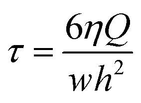 | (1) |
2.6 Statistical analysis
All experiments were repeated twice with at least four replicates in each repetition. For comparative studies, student's t-test was used for statistical analysis. Differences were considered statistically significant if p < 0.05.3. Results and discussion
3.1 Characterization of PSS–graphene
Poly(sodium-4-styrenesulfonate) (PSS) is a cation exchange polyelectrolyte commonly used to produce mechanically stable and reproducible coatings on various materials. When grafted on graphene, PSS not only prevents graphene flakes from restacking via van der Waals forces, but also dramatically improves the hydrophilicity. PSS is noncytotoxic and may be applied in drug delivery.27The functional groups on the surface of graphene, determined by FTIR spectrometry, are shown in Fig. 1a. PSS–graphene has broadened peaks at 1653, 1114, 1053, and 684 cm−1, indicating the presence of S![[double bond, length as m-dash]](https://www.rsc.org/images/entities/char_e001.gif) O, C–S, S–OH, and aromatic rings, respectively. These peaks were also found in PSS, indicating the successful grafting of PSS anions to the exfoliated graphite surface during the electrochemical exfoliation process. The peak at 1697 cm−1 shown for PSS–graphene is attributed to CO, reflecting the oxidation reaction that occurred during the electrochemical exfoliation process.
O, C–S, S–OH, and aromatic rings, respectively. These peaks were also found in PSS, indicating the successful grafting of PSS anions to the exfoliated graphite surface during the electrochemical exfoliation process. The peak at 1697 cm−1 shown for PSS–graphene is attributed to CO, reflecting the oxidation reaction that occurred during the electrochemical exfoliation process.
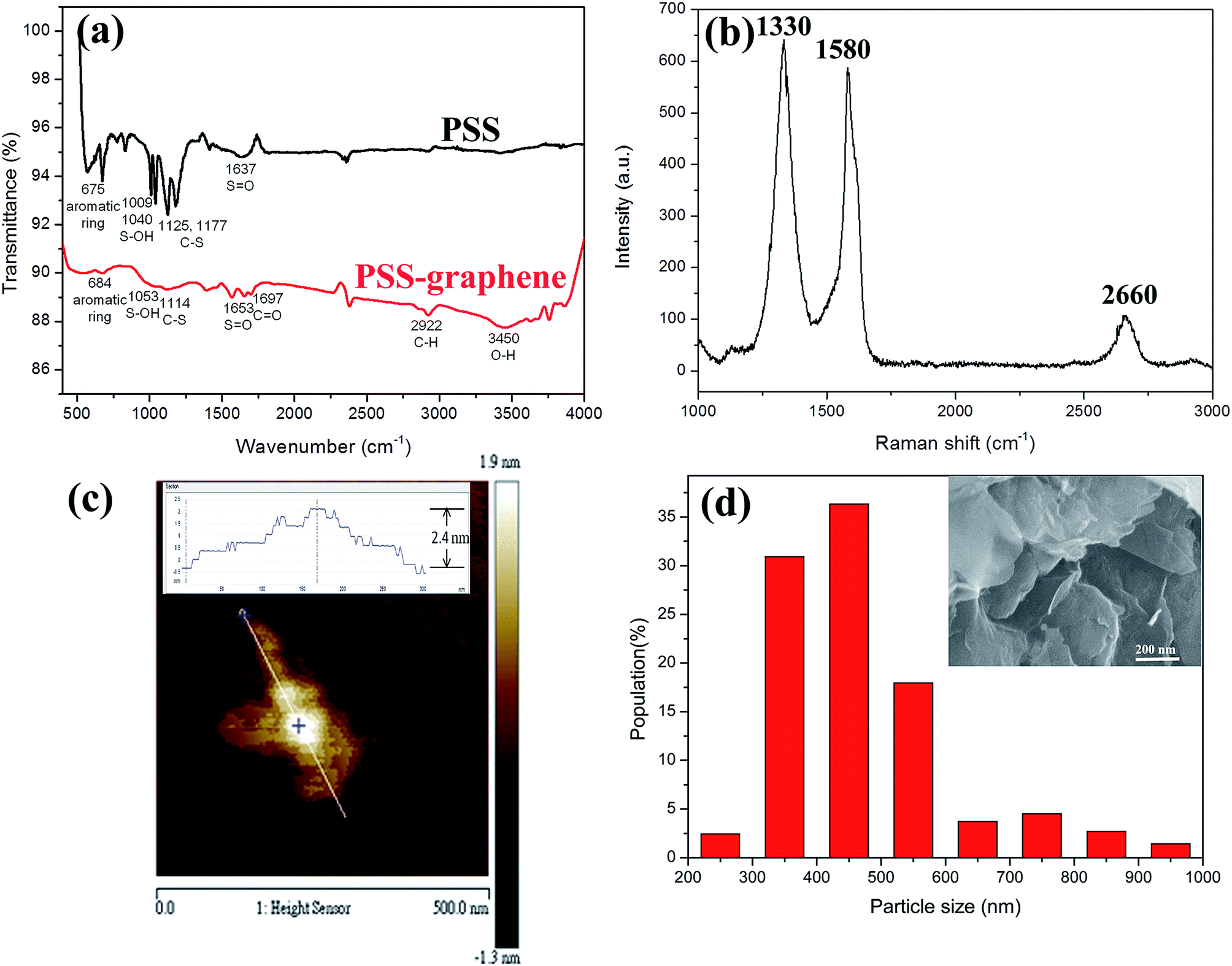 | ||
| Fig. 1 Characterization of chemical and physical properties of PSS–graphene. (a) FTIR spectrum of PSS and PSS–graphene, (b) Raman spectrum of PSS–graphene, (c) AFM images of PSS–graphene (the inset picture shows the cross-sectional height profile of the PSS–graphene), and (d) lateral size distribution (bottom) and morphology (inset) of PSS–graphene. | ||
For graphene with a few layers, the peak at 1320 cm−1 (D-band) reflects the defects of the graphite material, and the peak at 1580 cm−1 (G-band) signifies the sp2 hybridization of graphitic carbon. The 2D-band at 2650–2670 cm−1 is attributed to two phonon double resonance modes. The relative intensity ratio of 2D- and G-bands (I2D/IG) is an index of the layer number of the synthesized graphene. The Raman spectrum of the PSS–graphene (Fig. 1b) clearly indicates that the D-band is higher than the G-band, showing that the structure of the PSS–graphene contains amorphous carbon and defects generated by the electrochemical exfoliation process. Compared to the I2D/IG ratio of 1.5 to 2 reported for single-layer graphene, the I2D/IG ratio of PSS–graphene synthesized in this study was approximately 0.26. It was therefore estimated that the PSS–graphene fabricated through the electrochemical exfoliation processes is a multiple-layer graphene. This result is consistent with that obtained from AFM and SEM (Fig. 1c and inset of Fig. 1d), which is widely used for analyzing the thickness of graphene. The AFM result showed that the thickness of the PSS–graphene was approximately 2.4 nm. The size distribution of the obtained PSS–graphene ranged from 200 to 600 nm, as shown in Fig. 1d. The dispersion behavior in the DD water was obtained, and the zeta potential of dispersed PSS–graphene was −30 mV; this suggests that the PSS–graphene is highly hydrophilic and could stably disperse in DD water.
3.2 Cytotoxicity of HMEC-1 cells incubated with PSS–graphene under a static state
Different concentrations of PSS–graphene were tested on HMEC-1 cells, and cell viability was measured by cell proliferation (MTS) assay (Promega) after 24 hours of static culture, as shown in Fig. 2. At concentrations of 5, 10, 20, and 40 mg ml−1, PSS–graphene did not result in detectable damage to the HMEC-1 cells. Conversely, HMEC-1 cells incubated with 80 mg ml−1 of PSS–graphene showed a death rate of up to 40%.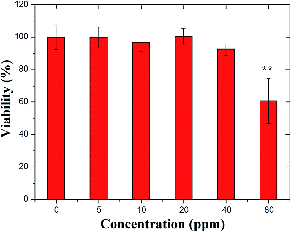 | ||
| Fig. 2 Effects of different concentrations of PSS–graphene on HMEC-1 viability under static conditions. The cell viability was determined by MTS assay. * indicates p < 0.05. | ||
The gross cell morphology reflecting the general health status of the cells was also examined through optical microscopy. The images shown in Fig. 3 also indicate no obvious difference between normal and 5, 10, 20, and 40 mg ml−1 PSS–graphene-treated HMEC-1 cells, even when black agglomerates could be clearly observed on the cell surface. Consistent with the finding of the MTS assay, cells treated with 80 mg ml−1 PSS–graphene exhibited a less rounded morphology, reflecting poor physiology of the cells.
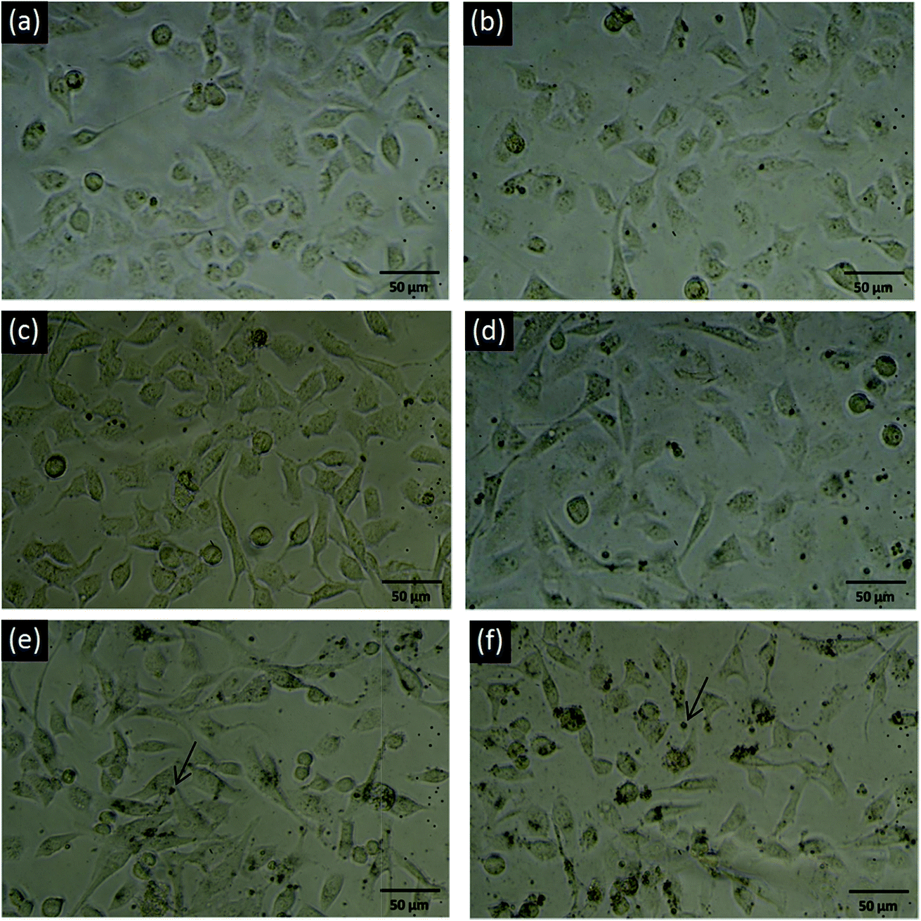 | ||
| Fig. 3 Optical microscopy images of PSS–graphene-treated HMEC-1 cells under static conditions. (a) 0 mg ml−1; (b) 5 mg ml−1; (c) 10 mg ml−1; (d) 20 mg ml−1; (e) 40 mg ml−1; (f) 80 mg ml−1. The arrows indicate PSS–graphene. | ||
Fig. 4 depicts the microstructure of HMEC-1 cells after incubating with graphene. The untreated HMEC-1 cells are shown in Fig. 4a. PSS–graphene accumulated by entangling with filopodia on the surface of the HMEC-1 cells after treatment with PSS–graphene for 4 h (Fig. 4b). According to previously published articles, nanomaterials with a lateral size of 350 nm could penetrate the cell membrane through phagocytosis with the assistance of filopodia.29 In this regard, we speculated that the PSS–graphene with a similar lateral size is very likely to be phagocytosed by HMEC-1 cells after adhering to the cell surface.
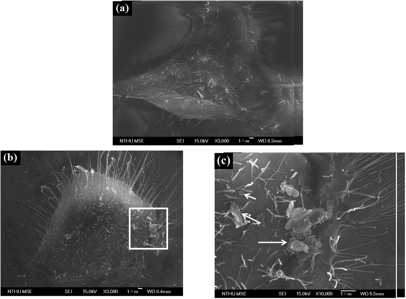 | ||
| Fig. 4 Effects of PSS–graphene treatment on HMEC-1 cell morphology. SEM images of the cells (a) without and (b) with PSS–graphene for 4 h. (c) Magnified image of the area boxed in (b). The arrows indicate PSS–graphene. | ||
To investigate whether PSS–graphene can penetrate into cells, PSS–graphene was first conjugated with Dylight 488 and confocal microscopy was then utilized to verify the subcellular location of the materials. Results shown in Fig. 5 demonstrated that PSS–graphene-Dylight 488 (green, marked with arrows) could be detected in the same longitudinal section plane as the nucleus (blue), suggesting that HMEC-1 cells phagocytosed PSS–graphene.
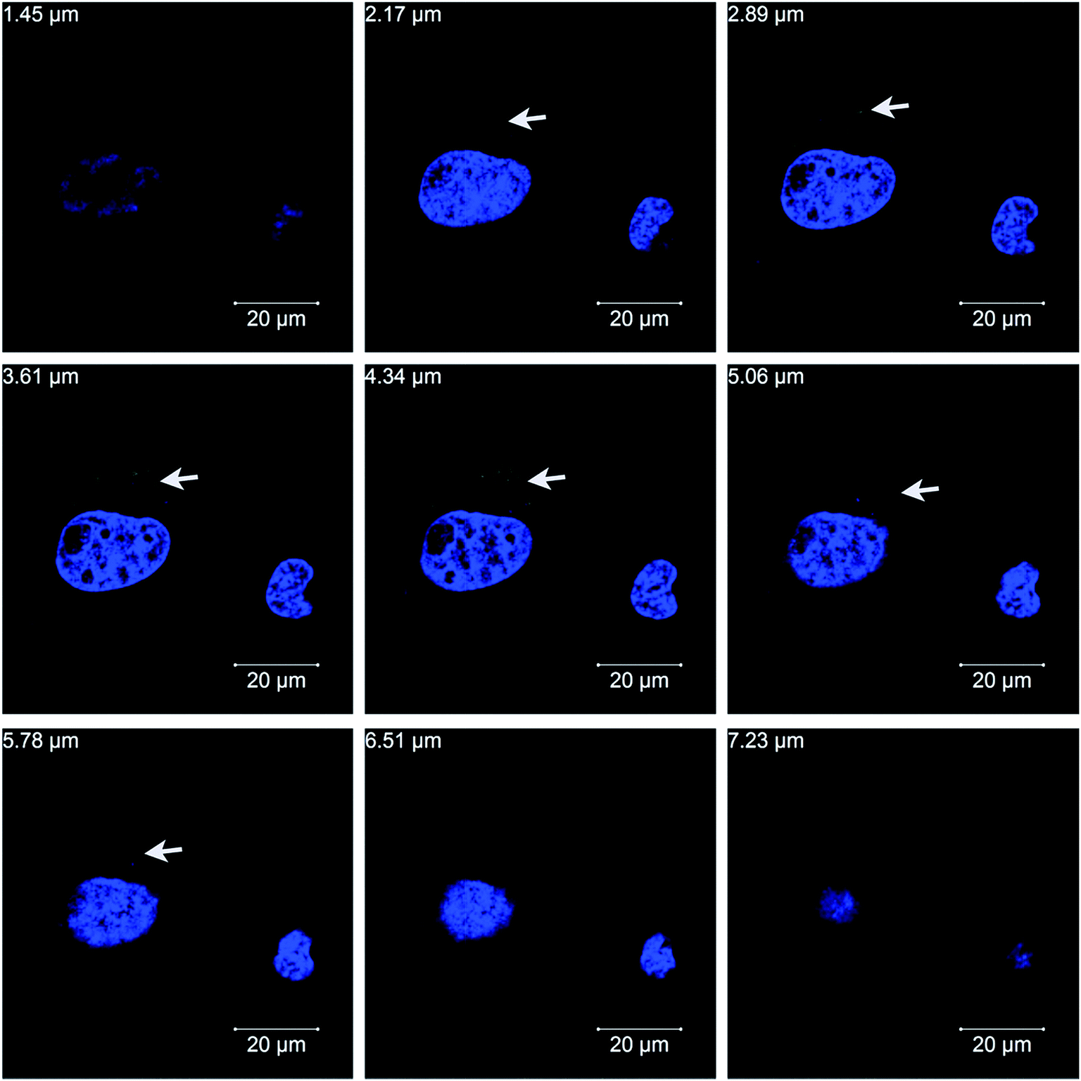 | ||
| Fig. 5 Confocal microscopic images of the uptake of PSS–graphene into HMEC-1 cells with continuous longitudinal section planes ranging from 1.45–7.23 μm. The nuclei were stained blue (DAPI) and PSS–graphene-Dylight 488 exhibits a green color. | ||
3.3 Cytotoxicity of HMEC-1 cells incubated with PSS–graphene under dynamic conditions
A microfluidic chip equipped with a microchannel was used to evaluate the cytotoxicity of PSS–graphene to HMEC-1 cells under flowing conditions to simulate blood flow and the shear stress exerted on the vessel walls. Fig. 6a and 7a show the morphology of normal HMEC-1 cells grown in the microchannel under a shear stress of 10 dynes per cm2. Interestingly, HMEC-1 cells grown under the same flow rates in the medium containing 80 mg ml−1 PSS–graphene did not display obvious differences in cell number (Fig. 6a and b) or morphology (Fig. 7b) compared to those grown in the absence of a PSS–graphene control. Treatment of the cells for longer periods gradually decreased cell viability; however, little difference was observed between the results of the control and the PSS–graphene treated sets (Fig. 6b). Increasing the shear force to 20 dynes per cm2 did not yield significant differences in cell viability between the control and PSS–graphene treated sets (Fig. 6c) after either 4 h or 8 h of incubation. This finding is in contrast to what was observed for cells grown under static culture conditions, where only 60% of the HMEC-1 cells remained alive after incubation with 80 mg ml−1 of PSS–graphene (Fig. 2). This result strongly suggests that under static conditions, PSS–graphene will likely cause cell damage. It is likely that PSS–graphene with smaller lateral sizes will be phagocytosed via filopodia, and therefore contribute a negative influence on the HMEC-1 cells. The cytotoxicity of cells grown in a flowing culture with PSS–graphene mimicking blood circulation with a shear stress of 10–20 dynes per cm2 decreased. These results imply that the longer time period PSS–graphene accumulated and adhered on the cell membranes, the higher cell cytotoxicity PSS–graphene caused.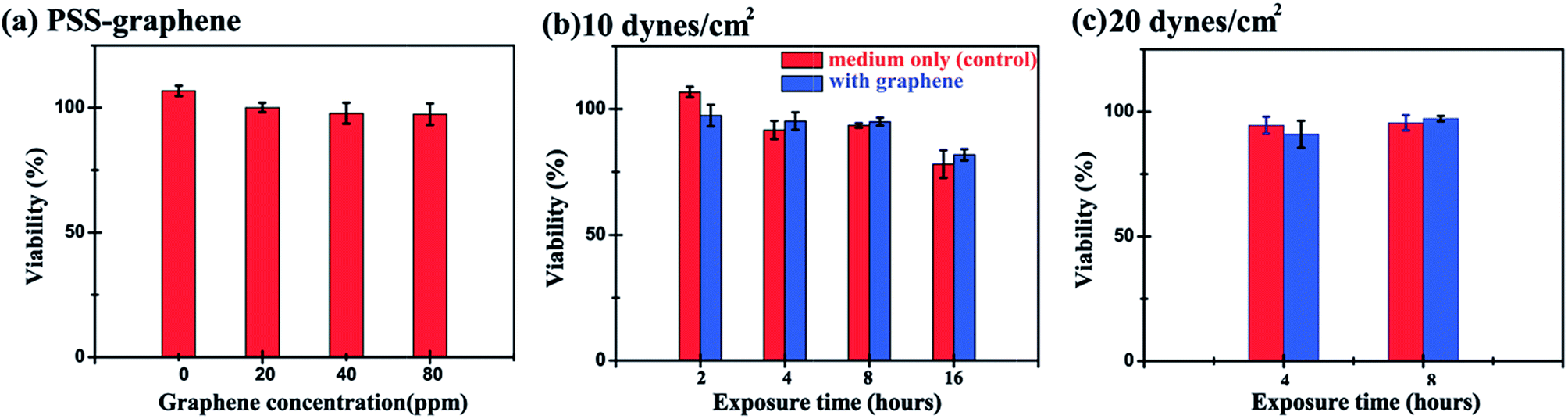 | ||
| Fig. 6 Effects of different concentration of PSS–graphene, exposure time periods, and shear stress on HMEC-1 cell viability under dynamic conditions. (a) Exposure of the cells to different concentrations of PSS–graphene under 10 dynes per cm2 of shear stress for 2 h. (b) The effect of treatment time on the viability of HMEC-1 cells in the presence of 80 mg ml−1 of PSS–graphene at a fixed 10 dynes per cm2 shear stress. (c) HMEC-1 cell viability grown under a shear stress of 20 dynes per cm2 and exposure times of 4 h and 8 h in the presence of 80 mg ml−1 PSS–graphene. (*, p < 0.05; **, p < 0.005; ***, p < 0.001). | ||
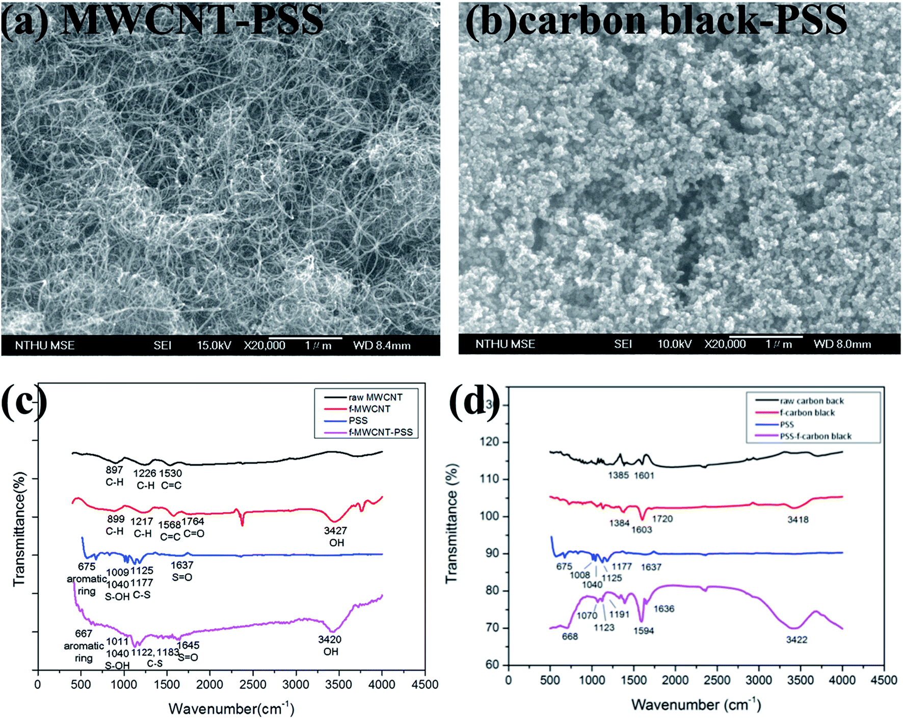 | ||
| Fig. 7 (a) Surface morphology and (c–d) FTIR spectrum of MWCNT–PSS (a and c) and carbon black–PSS (b and d). | ||
3.4 Cytotoxicity of HMEC-1 cells incubated with various PSS–carbon nanomaterials under dynamic conditions
It has been previously demonstrated that both the shape and extent of the agglomeration of carbon nanomaterials are critical conditions influencing cell damage under static condition. To investigate the geometry effect of carbon nanomaterials under dynamic conditions on the HMEC-1 cells, PSS–functionalized graphene, PSS–functionalized MWCNT (MWCNT–PSS, Fig. 7a and c) and PSS–functionalized carbon black (carbon black–PSS, Fig. 7b and d) were synthesized and characterized by SEM and FITR. Fig. 7c showed the FTIR spectra of the raw MWCNTs, f-MWCNTs, and PSS–f-MWCNT. The peaks at 3427 cm−1 (O–H group) and 1764 cm−1 (CO bond) resulting from functionalization were observed, and the peaks at 1645 cm−1 (SO), 1183 cm−1 (C–S), 1122 cm−1 (C–S), 1011 cm−1 (S–OH) and 667 cm−1 (aromatic ring) ensured that the f-MWCNTs were conjugated to PSS. Fig. 7d shows the FTIR spectra of the raw carbon black, f-carbon black and PSS–f-carbon black. The spectrum of f-carbon black has a broad band at 3418 cm−1 for the O–H stretching vibration and a small band at 1720 cm−1 for carbonyl CO stretching vibration, indicating that raw carbon black were successfully functionalized. Besides, in the spectrum of PSS–f-carbon black, the characteristic bands at 1636, 1191, 1123 and 1070 cm−1 are related to the SO, C–S, C–S, S–OH stretching modes, respectively, and 668 cm−1 can be attributed to aromatic ring in PSS.
Cells treated with different carbon nanomaterials, including PSS–graphene (Fig. 8b), PSS–f-MWCNT (Fig. 8c), and PSS–f-carbon black (Fig. 8d), were tested under dynamic flowing conditions at a concentration of 80 mg ml−1 and a shear stress of 10 dynes per cm2 to verify the impact of carbon nanomaterial shapes on cell viability under flowing conditions. Fig. 8e illustrates that in as short as a 2 h exposure time, the viability of both PSS–f-MWCNTs and PSS–f-carbon black treated cells was clearly lower than that of the control and the PSS–graphene treated cells. The negative effects caused by the PSS–f-MWCNTs and PSS–f-carbon black also became more dramatic with increasing incubation time (Fig. 8e). It has been previously proposed that the negative influence of MWCNTs on cultured cells in a flowing environment is due to its one-dimensional tubular structure that results in turbulent flow and an increased opportunity for its sharp ends to cause physical damage to the cells. It is less clear why PSS–f-carbon black also reduced HMEC-1 cell viability under such treatment conditions, although a large quantity of PSS–f-carbon black material was observed to have attached to the HMEC-1 cell surface in a dose-dependent manner, as depicted in the SEM images (Fig. 9).
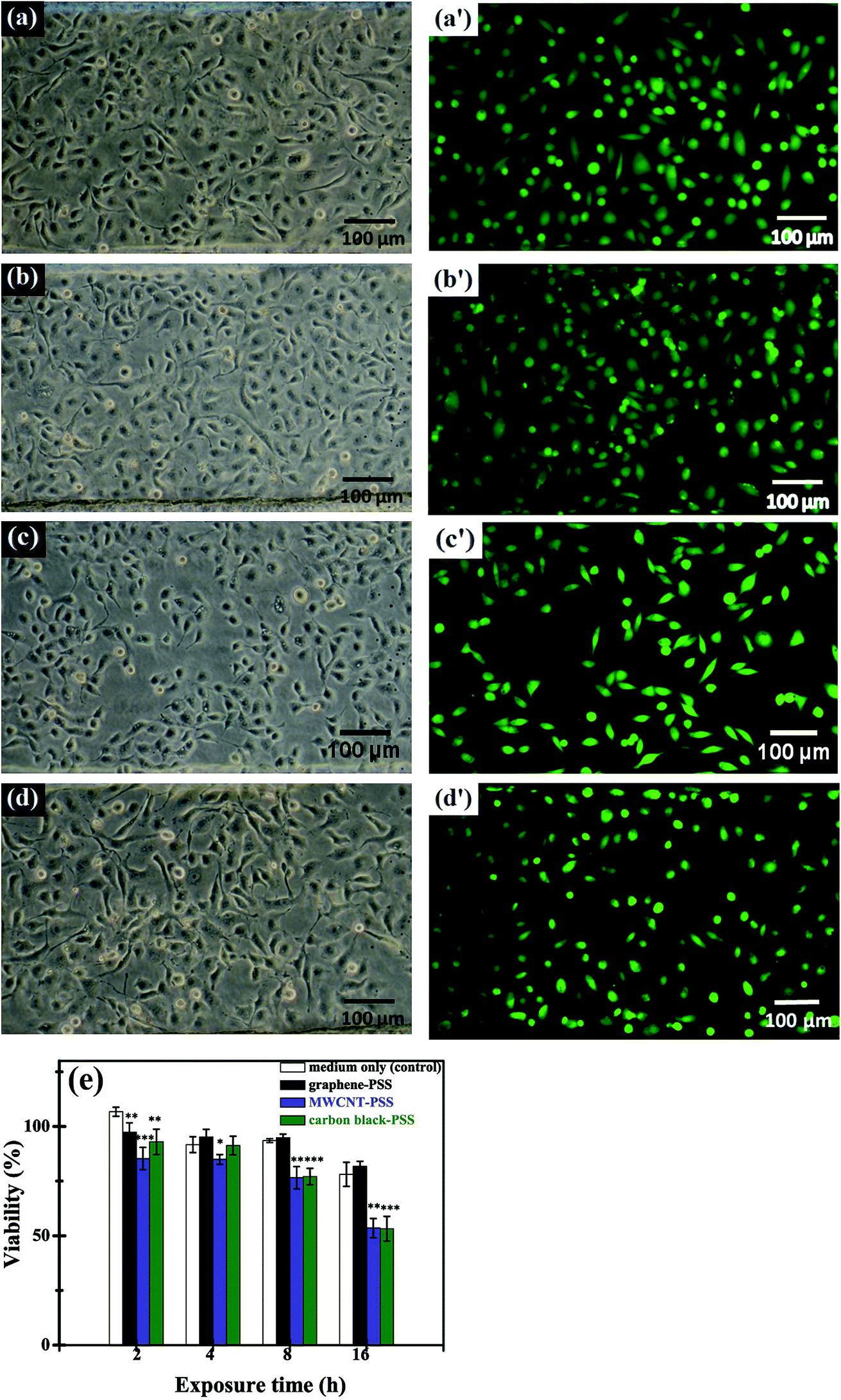 | ||
| Fig. 8 Effect of carbon nanomaterials on HMEC-1 cells grown under flowing dynamic conditions. The HMEC-1 cells were exposed to 10 dynes per cm2 of shear stress for 16 h in: (a) a regular culture medium without any treatment (control) and with (b) 80 mg ml−1 PSS–graphene, (c) 80 mg ml−1 PSS–f-MWCNTs, and (d) 80 mg ml−1 PSS–f-carbon black. The photos shown in (a), (b), (c), and (d) were pictured using bright field microscopy before the experiment and (a′), (b′), (c′), and (d′) were pictured under a fluorescence microscope after staining the cells. (e) Comparison of the viability of HMEC-1 cells after treatment with 80 mg ml−1 PSS–graphene, PSS–f-MWCNTs, and PSS–f-carbon black at 10 dynes per cm2 of shear stress for different periods of time. Data showing significant differences from that of the controls are marked with asterisks (*, p < 0.05; **, p < 0.005; ***, p < 0.001). | ||
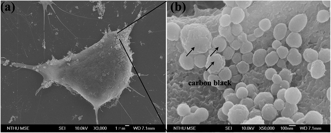 | ||
| Fig. 9 Effects of PSS carbon black treatment on HMEC-1 cell morphology under dynamic condition. (a) Low and (b) enlarged magnification SEM image of the cells treated with PSS–carbon black. | ||
4. Conclusions
A comparative study on the toxicity of PSS–graphene to HMEC-1 cells under static and dynamic culture conditions was completed. Under static culture conditions, the functionalized graphene easily accumulated and aggregated on the cell membranes and then entered the cell plasma with assistance of filopodia through the process of phagocytosis, resulting in the death of the cells. The cytotoxicity of PSS coated graphene decreased if the cells were grown in a flowing culture mimicking blood circulation with a shear stress of 10–20 dynes per cm2. This study demonstrated that functionalized graphene shows lower toxicity towards cells cultured in a dynamic culture as compared with in a static culture. The cytotoxicity of functionalized graphene is also lower than that of other carbon nanomaterials, including MWCNTs and carbon black, in a dynamic flowing culture due to the lateral-size effect and dispersion behavior. More toxicological studies of this material at higher doses that make use of animal models are necessary before functionalized graphene-related materials can be tested clinically for drug delivery.Conflicts of interest
There are no conflicts to declare.Acknowledgements
This study was supported by the Ministry of Science and Technology (MOST), Taiwan under project number MOST 105-2221-E-007-142 and MOST 106-2221-E-007-055, and by the National Tsing-Hua University under project no. 101N7049E1.References
- S. M. Moghimi, A. C. Hunter and J. C. Murray, FASEB J., 2005, 19, 311–330 CrossRef CAS PubMed
.
- A. K. Geim and K. S. Novoselov, Nat. Mater., 2007, 6, 183–191 CrossRef CAS PubMed
- C. Lee, X. D. Wei, J. W. Kysar and J. Hone, Science, 2008, 321, 385–388 CrossRef CAS PubMed
- A. A. Balandin, S. Ghosh, W. Z. Bao, I. Calizo, D. Teweldebrhan, F. Miao and C. N. Lau, Nano Lett., 2008, 8, 902–907 CrossRef CAS PubMed
- J. H. Chen, C. Jang, S. D. Xiao, M. Ishigami and M. S. Fuhrer, Nat. Nanotechnol., 2008, 3, 206–209 CrossRef CAS PubMed
- Y. W. Zhu, S. Murali, W. W. Cai, X. S. Li, J. W. Suk, J. R. Potts and R. S. Ruoff, Adv. Mater., 2010, 22, 3906–3924 CrossRef CAS PubMed
- X. M. Sun, Z. Liu, K. Welsher, J. T. Robinson, A. Goodwin, S. Zaric and H. J. Dai, Nano Res., 2008, 1, 203–212 CrossRef CAS PubMed
- Z. Liu, J. T. Robinson, X. M. Sun and H. J. Dai, J. Am. Chem. Soc., 2008, 130, 10876–10877 CrossRef CAS PubMed
- H. X. Wu, H. L. Shi, Y. P. Wang, X. Q. Jia, C. Z. Tang, J. M. Zhang and S. P. Yang, Carbon, 2014, 69, 379–389 CrossRef CAS
- L. Y. Tian, X. B. Pei, Y. X. Zeng, R. He, Z. J. Li, J. Wang, Q. B. Wan and X. Y. Li, J. Nanopart. Res., 2014, 16, 14 Search PubMed
- S. F. Mao, D. Gao, W. Liu, H. B. Wei and J. M. Lin, Lab Chip, 2012, 12, 219–226 RSC
- Y. Sheng, X. S. Tang, E. W. Peng and J. M. Xue, J. Mater. Chem. B, 2013, 1, 512–521 RSC
- Z. M. Markovic, L. M. Harhaji-Trajkovic, B. M. Todorovic-Markovic, D. P. Kepic, K. M. Arsikin, S. P. Jovanovic, A. C. Pantovic, M. D. Dramicanin and V. S. Trajkovic, Biomaterials, 2011, 32, 1121–1129 CrossRef CAS PubMed
- K. Yang, S. A. Zhang, G. X. Zhang, X. M. Sun, S. T. Lee and Z. A. Liu, Nano Lett., 2010, 10, 3318–3323 CrossRef CAS PubMed
- J. T. Robinson, S. M. Tabakman, Y. Y. Liang, H. L. Wang, H. S. Casalongue, D. Vinh and H. J. Dai, J. Am. Chem. Soc., 2011, 133, 6825–6831 CrossRef CAS PubMed
- T. R. Nayak, H. Andersen, V. S. Makam, C. Khaw, S. Bae, X. F. Xu, P. L. R. Ee, J. H. Ahn, B. H. Hong, G. Pastorin and B. Ozyilmaz, ACS Nano, 2011, 5, 4670–4678 CrossRef CAS PubMed
- Y. B. Zhang, S. F. Ali, E. Dervishi, Y. Xu, Z. R. Li, D. Casciano and A. S. Biris, ACS Nano, 2010, 4, 3181–3186 CrossRef CAS PubMed
- A. Sasidharan, L. S. Panchakarla, A. R. Sadanandan, A. Ashokan, P. Chandran, C. M. Girish, D. Menon, S. V. Nair, C. N. R. Rao and M. Koyakutty, Small, 2012, 8, 1251–1263 CrossRef CAS PubMed
- O. Akhavan, E. Ghaderi and A. Akhavan, Biomaterials, 2012, 33, 8017–8025 CrossRef CAS PubMed
- Y. L. Chang, S. T. Yang, J. H. Liu, E. Dong, Y. W. Wang, A. N. Cao, Y. F. Liu and H. F. Wang, Toxicol. Lett., 2011, 200, 201–210 CrossRef CAS PubMed
- M. Wojtoniszak, X. C. Chen, R. J. Kalenczuk, A. Wajda, J. Lapczuk, M. Kurzewski, M. Drozdzik, P. K. Chu and E. Borowiak-Palen, Colloids Surf., B, 2012, 89, 79–85 CrossRef CAS PubMed
- K. Yang, H. Gong, X. Z. Shi, J. M. Wan, Y. J. Zhang and Z. Liu, Biomaterials, 2013, 34, 2787–2795 CrossRef CAS PubMed
- K. Wang, J. Ruan, H. Song, J. L. Zhang, Y. Wo, S. W. Guo and D. X. Cui, Nanoscale Res. Lett., 2011, 6, 8 Search PubMed
- D. Kim, Y. S. Lin and C. L. Haynes, Anal. Chem., 2011, 83, 8377–8382 CrossRef CAS PubMed
- N. J. Kent, L. Basabe-Desmonts, G. Meade, B. D. MacCraith, B. G. Corcoran, D. Kenny and A. J. Ricco, Biomed. Microdevices, 2010, 12, 987–1000 CrossRef CAS PubMed
- J. A. Simoes, D. M. Citron, A. Aroutcheva, R. A. Anderson, C. J. Chany, D. P. Waller, S. Faro and L. J. D. Zaneveld, Antimicrob. Agents Chemother., 2002, 46, 2692–2695 CrossRef CAS PubMed
- A. H. Cory, T. C. Owen, J. A. Barltrop and J. G. Cory, Cancer Commun., 1991, 3, 207–212 CAS
- C. Bussy, H. Ali-Boucetta and K. Kostarelos, Acc. Chem. Res., 2013, 46, 692–701 CrossRef CAS PubMed
- H. Yue, W. Wei, Z. G. Yue, B. Wang, N. N. Luo, Y. J. Gao, D. Ma, G. H. Ma and Z. G. Su, Biomaterials, 2012, 33, 4013–4021 CrossRef CAS PubMed
Footnote |
| † Electronic supplementary information (ESI) available. See DOI: 10.1039/c7ra08286j |
| This journal is © The Royal Society of Chemistry 2017 |