 Open Access Article
Flexible and high capacity lithium-ion battery anode based on a carbon nanotube/electrodeposited nickel sulfide paper-like composite†
Peng Fana,
Hao Liu *bcd,
Libing Liao*a,
Jinzhou Fua,
Zhen Wangb,
Guocheng Lva,
Lefu Meia,
Huiying Haob,
Jie Xingb and
Jingjing Dongb
aSchool of Materials Science and Technology, China University of Geosciences, Beijing, 100083, P. R. China. E-mail: lbliao@cugb.edu.cn
bSchool of Science, China University of Geosciences, Beijing, 100083, P. R. China. E-mail: liuhao1398@cugb.edu.cn
cHubei Key Laboratory of Ferro & Piezoelectric Materials and Devices, Faculty of Physics & Electronic Science, Hubei University, Wuhan, 430062, P. R. China
dBeijing Key Laboratory of Optical Detection Technology for Oil and Gas, China University of Petroleum, Beijing, 102249, P. R. China
First published on 25th October 2017
Abstract
The integration of flexible carbon-based materials and high capacity anode materials is an effective route to obtain superior flexible electrode materials. In this work, nickel sulfide nanoparticles were electrodeposited on a CNT thin film to form a paper-like composite (NS@CNT). As a binder-free flexible Li-ion battery anode, a record specific capacity to date of ∼845 mA h g−1 at a current density of 60 mA g−1 in terms of the mass of the composite has been achieved. The high capacities were mainly attributed to reversible conversion reactions of nickel sulfide and the capacitance effect of the nanostructured composite.
1. Introduction
In recent years, flexible and wearable power storage devices have been urgently needed with the rapid development of flexible and wearable electronics, such as flexible displays, smart clothes, electronic skins, bendable smart phones and implantable medical devices.1 Among the flexible power storage devices, flexible Li-ion batteries (LIBs) have drawn great attention because of their high energy densities. Flexible anodes are essential for obtaining such flexible LIBs. Carbon-based materials including carbon fibers,2,3 carbon nanotubes (CNTs)4,5 and graphene6 are flexible and lithium-active, leading to their wide use as flexible LIB anodes. Nevertheless, the capacities of these materials are generally lower than 600 mA h g−1,7,8 which cannot meet the demand of the rapid development of flexible electronic devices.Integration of flexible carbon-based materials and high capacity anode materials (such as transition-metal oxides or transition-metal sulfides) without binders/additives can improve the capacity effectively.4,5,9–12 Among the carbon-based materials, CNTs are good candidates as flexible current collectors for LIBs due to their extremely high specific surface area, robust mechanical properties and excellent electronic conductivity. For example, Liangbing Hu et al. demonstrated a new structure of thin, flexible Li-ion batteries using CNT thin films as current collectors, which showed good electrochemical performance.9,13 Shu Luo et al. reported binder-free LiCoO2/CNTs for a Li-ion battery, and these binder-free LiCoO2/CNT cathodes exhibited high electrical conductivity, great flexibility, high energy density, and outstanding cycling stability.11 Lukman Noerochim et al. prepared a free-standing SWCNT/SnO2 paper electrode as an anode for a Li-ion battery, and the paper electrode showed a high specific discharge capacity and very stable cycling stability.12
Nickel sulfide as a promising anode material draws tremendous attention due to its high theoretical capacity and low cost.14 The family of nickel sulfides consists of a series of compounds with different ratios of N to S elements, including Ni3S2, Ni6S5, Ni7S6, NiS, and NiS2. In particular, Ni3S2, NiS, and NiS2 have gained much interest for lithium storage.15–26 However, the large volume change during the charging/discharging processes and the poor electronic conductivity of the nickel sulfide electrode materials can seriously reduce their electrochemical performance. The combination of nickel sulfides with carbon-based materials (graphene, carbon nanotubes, etc.) can effectively improve their electrochemical properties. For example, Abdel Hamid et al.27 synthesized graphene-wrapped nickel sulfide nanoprisms, achieving a specific capacity of over 1200 mA h g−1 after 100 cycles. Mahmood et al.28 reported a facile hydrothermal approach for the synthesis of a nickel sulfide/nitrogen-doped graphene composite electrode, which dramatically improved the electrochemical properties of nickel sulfide.
The LIB electrode made by the traditional tape-casting on a flat current collector method cannot meet the requirements of such flexible electronic devices. Therefore, alternative methods which are suitable for the fabrication of flexible battery electrodes need to be developed urgently. Electrodeposition can directly anchor electroactive materials on current collectors without using polymer binders or conducting agents, ensuring good attachment of the active materials on the flexible current collectors. Moreover, it can be used in industry with facile operation and low cost.
In the present work, nickel sulfide was electrodeposited on a CNT thin film to form a composite (NS@CNTs) as a binder-free flexible anode material for LIBs. The special interspace structure of the CNT thin film can effectively accommodate the volume expansion of the nickel sulfide during charge/discharge cycling. Therefore, the NS@CNT composite electrode exhibited high lithium-storage capacity and remarkable capacity retention performance. Moreover, the origin of the additional capacities that often exist in transition-metal sulfide electrodes is investigated in detail.
2. Experimental section
2.1 Chemicals
All the chemical reagents in this study are of analytical grade, including nickel chloride (NiCl2·6H2O, Beijing Chemical Works) and thiourea (H2NCSNH2, Beijing Chemical Works). The CNT thin film was purchased from Suzhou Hengqiu Graphene Technology Co., Ltd. All aqueous solutions were prepared with deionized (DI) water.2.2 Preparation of NS@CNTs
A piece of 1 cm × 1.5 cm CNT thin film (a CNT thin film with a thickness of ∼20 μm) was clipped and cleaned by ethanol and deionized water several times, followed by drying at 60 °C for 12 h under vacuum. The electrodeposition solution was composed of 0.1 M nickel chloride hexahydrate and 1.5 M thiourea. In order to overcome the poor hydrophilicity of the CNT thin film in aqueous electrolyte, a small amount of ethanol was added to the electrolyte. Before the deposition, the CNT thin film was placed into the electrolyte and ultrasonic radiation was applied for 5 min. Then, the deposition was conducted with a pulse voltage method at room temperature using an electrochemical workstation (Ivium-Vertex, Vium Technologies, Holland). The CNT thin film was fixed onto the working electrode, and a Pt sheet and Ag/AgCl electrode served as the counter electrode and the reference electrode, respectively. During the pulse deposition, the low voltage was set at −0.9 V and kept for 0.5 seconds, and the high voltage was set at −0.5 V and kept for 1 second. After electrodeposition, the NS@CNT composite was removed from the deposition bath, washed with deionized water and dried at 60 °C for 12 h under vacuum. The mass loading of the deposit can be controlled by changing the deposition cycles. In the present work, the mass loading was in the range of ∼1–2 mg cm−2.2.3 Characterization
The NS@CNT composite was characterized by X-ray diffraction (XRD, D8 Advance, Bruker, Germany) with Cu Kα radiation (λ = 1.5406 Å) and X-ray photoelectron spectroscopy (XPS, ESCALab250, Thermo Scientific, American) with monochromatic 150 W Al Kα radiation. The morphology was investigated by scanning electron microscopy (FESEM, MERLIN VP Compact, ZEISS, Germany) equipped with energy-dispersive spectroscopy (EDS). Transmission electron microscopy (TEM, JEOL 2010F, Japan) was also carried out for the microstructural investigation of the sample.2.4 Electrochemical measurements
The electrochemical performance was evaluated using CR2032 coin cells assembled in a high-purity argon-filled glove box with the moisture and oxygen content maintained below 0.1 ppm. The NS@CNT composite was directly used as the working electrode, and pure lithium foil was used as the counter electrode. The separator was Celgard 2400. The electrolyte was 1.0 M LiPF6 in ethylene carbonate/ethyl methyl carbonate/dimethyl carbonate solvent (1![[thin space (1/6-em)]](https://www.rsc.org/images/entities/char_2009.gif) :
:![[thin space (1/6-em)]](https://www.rsc.org/images/entities/char_2009.gif) 1
1![[thin space (1/6-em)]](https://www.rsc.org/images/entities/char_2009.gif) :
:![[thin space (1/6-em)]](https://www.rsc.org/images/entities/char_2009.gif) 1 v/v/v, Shenzhen Keijing Star Tech. Co.). The cells were aged for 12 h before measurement. All cyclic voltammetry tests were performed on an electrochemical workstation (Ivium-Vertex, Ivium Technologies, Holland). The galvanostatic charge/discharge tests were carried out using a Battery Testing system (CT-4008, NEWARE, China) with a voltage window of 3.0–0.0 V vs. Li+/Li at room temperature.
1 v/v/v, Shenzhen Keijing Star Tech. Co.). The cells were aged for 12 h before measurement. All cyclic voltammetry tests were performed on an electrochemical workstation (Ivium-Vertex, Ivium Technologies, Holland). The galvanostatic charge/discharge tests were carried out using a Battery Testing system (CT-4008, NEWARE, China) with a voltage window of 3.0–0.0 V vs. Li+/Li at room temperature.
3. Results and discussion
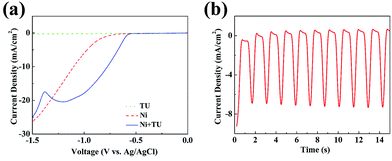
The NS@CNT composite was electrodeposited by a pulse voltage method in a three-electrode system. Before that, linear-sweep voltammetry (LSV) was carried out in three different aqueous electrolytes containing (i) 1.5 M thiourea (TU), (ii) 0.1 M NiCl2·6H2O and (iii) 0.1 M NiCl2·6H2O with 1.5 M TU. Fig. 1a shows their corresponding cathodic linear-sweep curves. The current density is close to zero in the aqueous electrolyte (i), indicating there are no obvious electrochemical reactions on the surface of the CNTs. As a contrast, an onset potential of −0.8 V in the aqueous electrolyte (ii) is observed, corresponding to the electro-reduction of Ni2+ to Ni metal. Nevertheless, the onset of bulk Ni deposition shifts to ∼−0.6 V after introducing TU into the electrolyte containing NiCl2·6H2O. In addition, a wide hump around ¬1.0–¬1.2 V can be observed, relating to the formation of nickel sulfide. When the TU is added, partial Ni2+ ions are complexed with TU in the form of NiCS(NH2)22+. Therefore, the possible formation mechanism of the electrodeposited nickel sulfide is as follows:29| 3NiCS(NH2)22+ + 6e− → Ni3S2 + 2CN− + 2NH4+ + CS(NH2)2 | (1) |
In order to obtain conformal deposition of nickel sulfide on the CNTs, pulsed electrodeposition was carried out in aqueous electrolyte (iii). The low voltage and the high voltage were selected as −0.9 V and −0.5 V vs. Ag/AgCl during the deposition. A part of the I–t curves during the pulsed electrodeposition is shown in Fig. 1b, showing that the current densities were about −0.5 mA cm−2 and −7.5 mA cm−2, corresponding to the high and low voltages. The mass of Ni3S2 is ∼1.2 mg when the electrodeposition process is 900 cycles. The weight percentage of Ni3S2 in the composite is ∼67%.
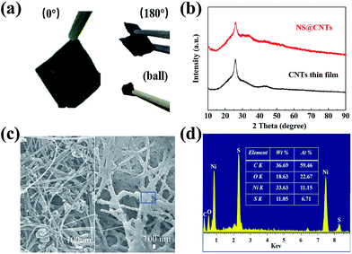
Fig. 2a displays photographs of the as-prepared NS@CNT composites at 0 degree bending, 180 degree bending and in the curled state. The composite shows excellent flexibility during bending tests, and could even be restored to its original form after being curled up into a ball. During these tests, no nickel sulfide particles dropped out from the CNT thin film, revealing that the electrodeposited nickel sulfides firmly anchor onto the flexible CNT thin film.
Fig. 2b shows XRD patterns of the CNT thin film and the NS@CNT composite. These two XRD patterns are the same, and the diffraction peaks at 2θ = 26° can be assigned to the CNT thin film. These results indicate that the as-deposited nickel sulfide is amorphous, which is consistent with other reports.30,31
Fig. 2c displays SEM images of the CNT thin film and the NS@CNT composite, respectively. The CNT thin film is composed of interlaced CNTs with an average diameter of ∼30 nm, and there are a lot of interspaces between the CNTs. It is obvious that the nickel sulfide was deposited on the porous nanostructured CNT thin film. The average diameter after deposition increases to ∼100 nm. In addition, the porous structure of the CNT thin film is maintained. Fig. 2d shows the corresponding EDS of the selected area of the NS@CNT composite, indicating that the atomic ratio of Ni and S elements is 11.15![[thin space (1/6-em)]](https://www.rsc.org/images/entities/char_2009.gif) :
:![[thin space (1/6-em)]](https://www.rsc.org/images/entities/char_2009.gif) 6.71. According to the values, the as-deposited nickel sulfide may be Ni3S2, which is consistent with the results reported in the literature.30,32 Moreover, the atomic percentage of the element O is up to 22.67%, indicating that a certain amount of oxides exists in the NS@CNT composite.
6.71. According to the values, the as-deposited nickel sulfide may be Ni3S2, which is consistent with the results reported in the literature.30,32 Moreover, the atomic percentage of the element O is up to 22.67%, indicating that a certain amount of oxides exists in the NS@CNT composite.
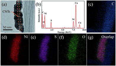
In order to reveal more information about the NS@CNT composite, TEM was carried out, and the results are shown in Fig. 3. The wire-like bright contrast in the core observed in Fig. 3a corresponds to the CNTs, and the nickel sulfide is uniformly deposited on the wall of the CNTs to form a core–shell structure. The spatial distributions of all of the elements are disclosed by EDS mapping (Fig. 3c–g), revealing that the deposit is composed of Ni, S and O elements.
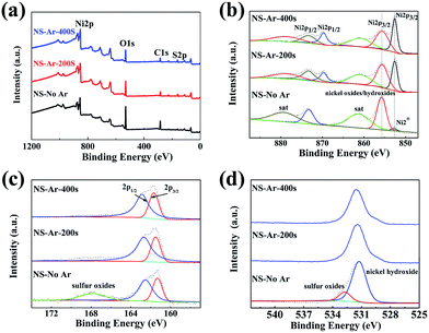
XPS measurements were carried out to analyze the surface chemical composition of the synthesized NS@CNT composite. Fig. 4a shows the XPS survey spectra of the sample cleaned by Ar sputtering at 0 s (NS-No-Ar), 200 s (NS-Ar-200 s) and 400 s (NS-Ar-400 s), revealing the presence of Ni, O, C and S elements in this composite. After Ar sputtering for 400 s, the relative intensity of O 1s decreased from ∼78% to ∼44% compared to that of the pristine sample. Meanwhile, the relative intensity of S 2p increased to ∼14%. Fig. 4b–d are the fine spectra of the Ni, O and S elements, showing the evolution of these elements in the cleaning processes. The Ni 2p peaks are always characterized by a complex shape due to the presence of spin–orbit doublet and satellite peaks. In Fig. 4b, two peaks at 855.6 eV and 852.6 eV come from Ni 2p3/2 and the peaks at 873.3 eV and 869.5 eV are from Ni 2p1/2, attributed to the Ni in oxides/hydroxides and nickel sulfide, respectively. The other peaks at 879.5 eV and 861 eV can be assigned to their satellite peaks. The abundant existence of nickel oxide/hydroxide may be due to the fast oxidation of the fresh sample in air, which was difficult to avoid.31,33 After Ar sputtering, the relative intensity of the peaks at 852.6 eV and 869.5 eV relative to nickel sulfide dramatically increases, while the others at 855.6 eV and 873.3 eV relative to oxides/hydroxides become weaker, resulting from the removal of the surface oxide layer on the deposited nickel sulfide sample. Nevertheless, the peaks relative to the hydroxides still exist, indicating the formation of nickel hydroxide in the electrodeposition process.32 In addition, three peaks at around 162.5 eV, 161.5 eV and 168 eV (Fig. 4c) correspond to S 2p1/2, S 2p3/2 and sulfur oxides in the NS-No-Ar sample, revealing that most of the S species exist as S2−. After Ar sputtering, the peak related to sulfur oxides disappears, confirming the existence of surface oxidation.31 Fig. 4d shows the O 1s peaks at around 531.2 eV and 532.7 eV in the NS-No-Ar sample, which represent the BE value of Ni hydroxide and sulfur oxides, respectively. After Ar sputtering, the peak at 532.7 eV relative to the sulfur oxides disappears. At the same time, the relative intensity of the peak at 531.2 eV relative to Ni hydroxide becomes weaker but still exists, indicating that Ni hydroxide remains even after the surface layer is removed.
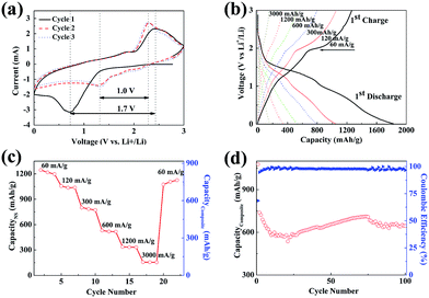
Cyclic voltammetry (CV) curves of the NS@CNT composite are shown in Fig. 5a. In the first cathodic scan, a strong and wide reduction peak at ∼0.7 V vs. Li+/Li is attributed to the conversion reaction of Ni3S2 to Li2S and Ni18 and the formation of the solid-electrolyte interphase (SEI) layer on the surface of the electrode due to electrolyte decomposition.19 The strong oxidation peak at ∼2.4 V vs. Li+/Li in the first anodic scan corresponds to the reversible conversion reaction of Li2S and Ni to Ni3S2,18,19 and the weak oxidation peak at ∼1.9 V vs. Li+/Li may be attributed to partial oxidation of the SEI layer. In the subsequent two scans, a couple of redox peaks at ∼1.3 V and ∼2.3 V vs. Li+/Li can be observed, which are assigned to the reversible conversion reactions of Li and Ni3S2 (Ni3S2 + 4Li+ + 4e− ↔ 3Ni + 2Li2S).14,34 In addition, the gap between these two peaks (1.0 V) is smaller than that in the first scan (1.7 V), indicating that the electrode polarization decreases after the first lithiation/delithiation process. Moreover, the profiles of the second and third cycles are similar, reflecting good reversibility of the conversion reactions on the NS@CNT electrode. Fig. 5b shows the galvanostatic charge–discharge curves of the NS@CNT composite electrode at various current densities. In general, the discharging and charging voltage plateaus mainly appear at ∼2.0 V and ∼1.2 V vs. Li+/Li, which correspond to the reversible conversion reaction of Li and Ni3S2. The first discharging and charging capacities tested at a current density of 60 mA g−1 in terms of the mass of the nickel sulfide are 1827 mA h g−1 and 1265 mA h g−1, with an initial coulombic efficiency of ∼69%. The high irreversible capacity loss may result from the decomposition of the electrolyte to form the SEI layer. Fig. 5c shows the rate performance of the NS@CNT composite. It exhibits high specific charging capacities of about 1265, 1056, 801, 530, 337, and 155 mA h g−1 in terms of the mass of the nickel sulfide only and about 845, 717, 544, 360, 228 and 105 mA h g−1 in terms of the mass of the composite at current densities of 60 mA g−1, 120 mA g−1, 300 mA g−1, 600 mA g−1, 1200 mA g−1 and 3000 mA g−1. The specific capacities of the NS@CNT electrode in terms of the mass of the nickel sulfide decrease with increasing current densities from 60 mA g−1 to 3000 mA g−1. However, the capacity recovers to 1106 mA h g−1 when the current density decreases back to 60 mA g−1, indicating the good cycle stability of the NS@CNT electrode. Fig. S1† shows that the CNT thin film has very low charging capacities at various current densities, indicating that the capacities of the NS@CNT composite are mainly contributed to by the electrodeposited nickel sulfide. We further compared the electrochemical performance of the NS@CNT composite with other reports about nickel sulfide anode materials, and the results are shown in Table S1.† The NS@CNT composite exhibits the highest specific capacities in terms of the total mass of the active materials and the current collector. A record specific capacity reported to date, i.e., 850 mA h g−1 at a current density of 60 mA g−1, has been achieved for nickel sulfide-based anodes. The above results reveal the tremendous advantages of the NS@CNT composite as a flexible LIB anode.
Fig. 5d shows the cycling performance of the NS@CNT composite at a current density of 300 mA g−1. After the first ten cycles, the specific capacity in terms of the mass of the composite decreases dramatically from 738 mA h g−1 to 580 mA h g−1, resulting from the irreversible capacity loss during SEI formation. In the subsequent cycles, the specific capacity increases gradually to 708 mA h g−1 at the 75th cycle, possibly due to the increase of the surface area of the disintegrated Ni3S2 during the charging/discharging processes. Then the specific capacity decreases to 644 mA h g−1 after 100 cycles. This may be due to the slow loss of active material caused by volume expansion during cycling. The good cycling performance of the electrode mainly originates from the special porous structure of the CNT thin film which could effectively mitigate the volume expansion. A high coulombic efficiency of ∼98% is maintained during the 100 cycles. The above results suggest that the NS@CNT composite could be a promising anode material candidate for flexible LIBs.
The specific capacities of the NS@CNT electrode in terms of the active materials are about 845 mA h g−1 at a current density of 60 mA g−1, much higher than the theoretical capacity (446 mA h g−1) of nickel sulfide (Ni3S2).15 In order to understand the origins of the additional capacities, CV curves were obtained at different scan rates, and the results are shown in Fig. 6a. The relationship between the measured current (i) and the scan rate (υ) follows the equations:
| i(V) = aυb | (2) |
lg![[thin space (1/6-em)]](https://www.rsc.org/images/entities/char_2009.gif) i(V) = b i(V) = b![[thin space (1/6-em)]](https://www.rsc.org/images/entities/char_2009.gif) lg lg![[thin space (1/6-em)]](https://www.rsc.org/images/entities/char_2009.gif) υ + lg υ + lg![[thin space (1/6-em)]](https://www.rsc.org/images/entities/char_2009.gif) a a
| (3) |
![[thin space (1/6-em)]](https://www.rsc.org/images/entities/char_2009.gif) i vs. log
i vs. log![[thin space (1/6-em)]](https://www.rsc.org/images/entities/char_2009.gif) υ. In general, the electrode is controlled by the diffusion process when the b-value is 0.5, while the capacitive response is dominant when the b-value is 1.0.35 Fig. 6b shows the calculated b-values for the NS@CNT composite electrode. At the potentials of 0.5 V vs. Li+/Li and 1.3 V vs. Li+/Li for the cathodic process, the b-values are very close to 0.5, which indicates that the charge storage mainly comes from the conversion reaction. At the potentials of 0.2 V vs. Li+/Li and 1 V vs. Li+/Li, the b-values are close to 0.7, which indicates that parts of the capacities come from capacitive effects. During the anodic process, the b-values are in the range of 0.55–0.85, also indicating that the capacitance effect makes an additional contribution to the total capacity of the NS@CNT composite electrode (especially in the high voltage regions). The above capacitive effects may arise from surface adsorption of Li ions on the NS@CNT composite,36 which may form a double-layer capacitor on the surface of the electrode.
υ. In general, the electrode is controlled by the diffusion process when the b-value is 0.5, while the capacitive response is dominant when the b-value is 1.0.35 Fig. 6b shows the calculated b-values for the NS@CNT composite electrode. At the potentials of 0.5 V vs. Li+/Li and 1.3 V vs. Li+/Li for the cathodic process, the b-values are very close to 0.5, which indicates that the charge storage mainly comes from the conversion reaction. At the potentials of 0.2 V vs. Li+/Li and 1 V vs. Li+/Li, the b-values are close to 0.7, which indicates that parts of the capacities come from capacitive effects. During the anodic process, the b-values are in the range of 0.55–0.85, also indicating that the capacitance effect makes an additional contribution to the total capacity of the NS@CNT composite electrode (especially in the high voltage regions). The above capacitive effects may arise from surface adsorption of Li ions on the NS@CNT composite,36 which may form a double-layer capacitor on the surface of the electrode.
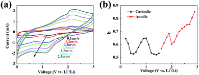 | ||
| Fig. 6 (a) Typical CV curves at various scan rates for the NS@CNT electrode. (b) Calculated b-values as a function of voltage for cathodic and anodic sweeps for the NS@CNT electrode. | ||
4. Conclusions
In summary, a flexible NS@CNT composite as a binder-free LIB anode was synthesized through a facile electrodeposition method. The composite electrode exhibited a record specific capacity of ∼845 mA h g−1 in terms of the mass of the composite (including active materials and CNT current collector) at a current density of 60 mA g−1. Moreover, its specific capacity remained at ∼644 mA h g−1 after 100 cycles at a current density of 300 mA g−1, revealing the good cycling stability of this composite. The high capacities were mainly contributed to by the reversible conversion reactions of nickel sulfide and the capacitance effect of the nanostructured composite. Therefore, the NS@CNT paper-like composite as an anode material showed great promise for flexible LIBs.Conflicts of interest
There are no conflicts to declare.Acknowledgements
This work was supported by the National Natural Science Foundation of China (No. 51502271 and 41672044); the Fundamental Research Funds for the Central Universities (No. 2652015186 and 2652015189); and the Open Funds of Hubei Key Laboratory of Ferro and Piezoelectric Materials and Devices (No. 201604).Notes and references
- W. Liu, M. S. Song, B. Kong and Y. Cui, Adv. Mater., 2017, 29, 1603436 CrossRef PubMed.
- S. J. Kim, M. C. Kim, S. B. Han, G. H. Lee, H. S. Choe, D. H. Kwak, S. Y. Choi, B. G. Son, M. S. Shin and K. W. Park, Nano Energy, 2016, 27, 545–553 CrossRef CAS.
- L. Zhang, Y. Huang, Y. Zhang, H. Gu, W. Fan and T. Liu, Adv. Mater. Interfaces, 2016, 3, 1500467 CrossRef.
- K. Fu, O. Yildiz, H. Bhanushali, Y. Wang, K. Stano, L. Xue, X. Zhang and P. D. Bradford, Adv. Mater., 2013, 25, 5109–5114 CrossRef CAS PubMed.
- Z. Chen, J. W. F. To, C. Wang, Z. Lu, N. Liu, A. Chortos, L. Pan, F. Wei, Y. Cui and Z. Bao, Adv. Energy Mater., 2014, 4, 1400207 CrossRef.
- L. Chen, G. Zhou, Z. Liu, X. Ma, J. Chen, Z. Zhang, X. Ma, F. Li, H. M. Cheng and W. Ren, Adv. Mater., 2016, 28, 510–517 CrossRef CAS PubMed.
- G. Zhou, F. Li and H. M. Cheng, Energy Environ. Sci., 2014, 7, 1307–1338 CAS.
- Y. Fei, D. T. Pham and Y. H. Lee, ChemSusChem, 2015, 8, 2284–2311 CrossRef PubMed.
- L. Hu, H. Wu, M. F. La, Y. Yang and Y. Cui, ACS Nano, 2010, 4, 5843–5848 CrossRef CAS PubMed.
- L. Hu, N. Liu, M. Eskilsson, G. Zheng, J. McDonough, L. Wågberg and Y. Cui, Nano Energy, 2013, 2, 138–145 CrossRef CAS.
- S. Luo, K. Wang, J. Wang, K. Jiang, Q. Li and S. Fan, Adv. Mater., 2012, 24, 2294–2298 CrossRef CAS PubMed.
- L. Noerochim, J.-Z. Wang, S.-L. Chou, D. Wexler and H.-K. Liu, Carbon, 2012, 50, 1289–1297 CrossRef CAS.
- L. Hu, J. W. Choi, Y. Yang, S. Jeong, F. La Mantia, L. F. Cui and Y. Cui, Proc. Natl. Acad. Sci. U. S. A., 2009, 106, 21490–21494 CrossRef CAS PubMed.
- S. C. Han, K. W. Kim, H. J. Ahn, J. H. Ahn and J. Y. Lee, J. Alloys Compd., 2003, 361, 247–251 CrossRef CAS.
- X. Rui, H. Tan and Q. Yan, Nanoscale, 2014, 6, 9889–9924 RSC.
- X. Xu, W. Liu, Y. Kim and J. Cho, Nano Today, 2014, 9, 604–630 CrossRef CAS.
- Y. Wang, Q. Zhu, L. Tao and X. Su, J. Mater. Chem., 2011, 21, 9248 RSC.
- D. Li, X. Li, X. Hou, X. Sun, B. Liu and D. He, Chem. Commun., 2014, 50, 9361–9364 RSC.
- W. Duan, W. Yan, X. Yan, H. Munakata, Y. Jin and K. Kanamura, J. Power Sources, 2015, 293, 706–711 CrossRef CAS.
- T. Takeuchi, H. Sakaebe, H. Kageyama, T. Sakai and K. Tatsumi, J. Electrochem. Soc., 2008, 155, A679–A684 CrossRef CAS.
- Y. Yamaguchi, T. Takeuchi, H. Sakaebe, H. Kageyama, H. Senoh, T. Sakai and K. Tatsumi, J. Electrochem. Soc., 2010, 157, A630–A635 CrossRef CAS.
- N. Feng, D. Hu, P. Wang, X. Sun, X. Li and D. He, Phys. Chem. Chem. Phys., 2013, 15, 9924–9930 RSC.
- J. Wang, S. Y. Chew, D. Wexler, G. X. Wang, S. H. Ng, S. Zhong and H. K. Liu, Electrochem. Commun., 2007, 9, 1877–1880 CrossRef CAS.
- Z. Zhang, H. Zhao, Q. Xia, J. Allen, Z. Zeng, C. Gao, Z. Li, X. Du and K. Świerczek, Electrochim. Acta, 2016, 211, 761–767 CrossRef CAS.
- J. Zhu, Y. Li, S. Kang, X.-L. Wei and P. K. Shen, J. Mater. Chem. A, 2014, 2, 3142–3147 CAS.
- Z. Zhang, H. Zhao, Z. Zeng, C. Gao, J. Wang and Q. Xia, Electrochim. Acta, 2015, 155, 85–92 CrossRef CAS.
- A. A. AbdelHamid, X. Yang, J. Yang, X. Chen and J. Y. Ying, Nano Energy, 2016, 26, 425–437 CrossRef CAS.
- N. Mahmood, C. Zhang and Y. Hou, Small, 2013, 9, 1321–1328 CrossRef CAS PubMed.
- S. W. Chou and J. Y. Lin, J. Electrochem. Soc., 2013, 160, D178–D182 CrossRef CAS.
- S. W. Chou and J. Y. Lin, J. Electrochem. Soc., 2015, 162, A2762–A2769 CrossRef CAS.
- H. Sun, D. Qin, S. Huang, X. Guo, D. Li, Y. Luo and Q. Meng, Energy Environ. Sci., 2011, 4, 2630–2637 CAS.
- C. W. Su, J. M. Li, W. Yang and J. M. Guo, J. Phys. Chem. C, 2014, 118, 767–773 CAS.
- F. Loglio, M. Innocenti, A. Jarek, S. Caporali, I. Pasquini and M. L. Foresti, J. Electroanal. Chem., 2010, 638, 15–20 CrossRef CAS.
- P. Poizot, S. Laruelle, S. Grugeon and J. M. Tarascon, J. Electrochem. Soc., 2002, 149, A1212 CrossRef CAS.
- K. Cao, L. Jiao, Y. Liu, H. Liu, Y. Wang and H. Yuan, Adv. Funct. Mater., 2015, 25, 1082–1089 CrossRef CAS.
- F. Beguin and E. Frackowiak, Supercapacitors: Materials, Systems, and Applications, Wiley-VCH, 2013 Search PubMed.
Footnote |
| † Electronic supplementary information (ESI) available. See DOI: 10.1039/c7ra08239h |
| This journal is © The Royal Society of Chemistry 2017 |

