
 Open Access Article
 This Open Access Article is licensed under a
 Creative Commons Attribution 3.0 Unported Licence
Electromagnetic interference shielding cotton fabrics with high electrical conductivity and electrical heating behavior via layer-by-layer self-assembly route
Mingwei Tian†
 *abc,
Minzhi Du†ab,
Lijun Qu*abc,
Shaojuan Chena,
Shifeng Zhuabc and
Guangting Hanbc
*abc,
Minzhi Du†ab,
Lijun Qu*abc,
Shaojuan Chena,
Shifeng Zhuabc and
Guangting Hanbc
aInstitute of Advanced Fibrous Materials and Applications, College of Textiles and Clothing, Qingdao University, Qingdao, Shandong 266071, P. R. China. E-mail: tmw0303@126.com; profqu@126.com
bLaboratory of New Fiber Materials and Modern Textile, The Growing Base for State Key Laboratory, Qingdao University, Qingdao, Shandong 266071, P. R. China
cCollaborative Innovation Center for Marine Biomass Fibers, Materials and Textiles of Shandong Province, Qingdao University, Qingdao, Shandong 266071, P. R. China
First published on 4th September 2017
Abstract
In our paper, multi-functional cotton fabrics with electrical and electromagnetic interference (EMI) shielding properties via layer-by-layer (LbL) electrostatic self-assembly approach were prepared. Chitosan was adopted as a polycation with graphene added by solution mixing, and poly(sodium 4-styrenesulfonate) (PSS) as a polyanion was deposited on cotton fabric substrate followed by the chitosan–graphene layer alternatively. Structural and morphological characterizations of the prepared LbL samples were carried out using SEM, AFM, XPS, and surface potential techniques. As expected, surface potential value exhibited an obvious “odd–even” regular pattern, which results from the alternating deposition of PSS and chitosan–graphene layers. Further, the electrical conductivity of the 10-layer-deposited fabric reached 1.67 × 10³ S m−1. The fabric also exhibits ultrastrong electromagnetic interference (EMI) shielding ability with a maximum SE value of 30.04 dB. The LbL fabric also possesses excellent electrical heating behaviors. The temperature of the resultant fabric would monotonically rise to the steady-state maximum value (ΔTmax) of 134 °C within 8 min when 7 V voltage was applied, and exhibit excellent stability and recyclability. In addition, various performances remained almost unchanged after 10 consecutive washing treatments. The modified cotton fabric with lightweight, flexible and high-performance EMI shielding properties could be applied in personal protective garments and industrial textiles.
1. Introduction
Over the past decades, electromagnetic radiation has become the fourth most serious source of public pollution after noise, water and air pollution, due to the advancement of electrification, and application of electromagnetic energy. Electromagnetic interference (EMI) refers to the unacceptable degradation of a system or devices due to undesirable radiation interference, and electrical signals originating elsewhere.1 Electrical devices may fail to operate normally when exposed to EMI,2 and such failures could have critical impact on highly sensitive electronic devices used for civil, commercial, military, or other sophisticated technological fields.3 In addition, electromagnetic waves could cause serious damage to human health, with symptoms such as insomnia, nervousness, languidness and headaches, and even diseases such as cancers, tumors, Alzheimer's and Parkinson's diseases.4 Due to such problems caused by EMI, ultrastrong and effective electromagnetic shielding composite materials need further development.With various desirable properties and being in close contact with human beings, textiles have taken on an emerging role in applications of electromagnetic interference (EMI) shielding in electronic industries as well as protective garments. Textiles are intrinsically electrical insulating materials and non EMI shielding materials. Yet, various methods can be adapted to make them electrically conductive and successfully turn to be EMI shielding materials. In general, metallic materials that can reflect or conduct electrons effectively, such as aluminum,5 copper,6 silver,7 nickel8 and stainless steel9 were best candidates composites for preventing EMI. Yet, there were some usability problems, e.g. mass density, susceptibility to oxidative corrosion, expensiveness and poverty in processing.
Recently, carbon-based materials with high electrical conductivity, light-weight, flexibility and large specific surface area have been widely employed as conductive fillers to fabricate EMI shielding functional materials.10 Cao et al.11 novelty introduced ferroferric oxide into multiwalled carbon nanotube-based composites for enhancing magnetic properties to endow EMI attenuation. Ultrathin graphene is proving to be a particularly attractive EMI shielding material, because of its unique physical and chemical properties.12 Chemical graphitized r-GOs composites exhibited high efficiency EMI shielding at elevated temperatures, and reflected different temperature-dependent permittivity and EMI SE with changing mass ratio.13 Shen et al.14 fabricated ultrathin graphite-like graphene films (G-film) by graphitizing graphene oxide (GO) films and the resulting graphene film with only ≈8.4 μm in thickness possessed excellent EMI shielding effectiveness of ≈20.1 dB excellent mechanical flexibility and structure integrity during bending. And a microcellular graphene foam by using a hydrazine-foaming method from GO film could exhibit an improved average SEtotal of ∼26.3 dB over a broad band frequency range of 8.2–59.6 GHz.15 In addition, beside pristine graphene film or foam, graphene based polymer composites could also possess remarkable EMI shielding properties. Li et al.16 reported an ultrathin polyimide/graphene compounded foams, and it exhibited much higher SE up to 24 dB with the thickness about 24 μm over the frequency range of 8–12 GHz and gradually raised to 43 and 51 dB when the thickness increased to 51 and 73 μm, respectively. And Shen et al.17 fabricated an ultralight weight and compressible polymer/graphene foams by simple solution dip-coating with highly porous network structure which could show promising adjustable EMI shielding. EMI shielding performance of composite materials can be tunable control via structure design, Cao et al.10,18 designed double-layered shielding attenuators with ultrathin graphene papers and exhibited highly effective shielding capabilities. Multilayer graphene/PVA composite films with good mechanical flexibility were fabricated into paraffin-based sandwich structures to enhance EMI shielding.19
Furthermore, graphene-based functional fabrics with diverse properties, e.g. electrical conducting,20 thermal conducting,21 ultraviolet blocking,22,23 far-infrared emission,24 antibacterial25 and sensing26,27 have been widely explored. However, the fabric with EMI shielding properties endowing from graphene has not yet been investigated, and therefore in our work, graphene modified cotton fabric with EMI shielding properties was prepared through electrostatic self-assembly (ESA) principle of LbL technique. Poly(sodium 4-styrenesulfonate) (PSS) and chitosan (CS) were applied as polyanion and polycation, respectively. The cotton fabric matrix was treated alternatively with PSS and CS sedimentary layer, further, CS was doped with graphene in order to enhance its conductivity and EMI shielding properties.
2. Experimental
2.1. Materials
Substrate fabric (100% cotton, plain-weave, 190 g m−2), supplied by Lutai Textile Group, China. Poly(sodium 4-styrenesulfonate) powder (PSS, average MW = ∼70000 kDa) and chitosan (CS) (deacetylation degree of 93% and MW = 200–300 kDa), purchased from Sigma-Aldrich. Graphene slurry (10 mg mL−1), donated by Jinan Shengquan Group, China. All other reagents and deionized water were used as required.2.2. Synthesis of polyelectrolyte and LbL cotton fabrics
The PSS was dissolved in deionized water with a concentration of 0.3 mg mL−1. At 30 °C, a 2% v/v acetic acid solution was used to dissolve chitosan and then graphene dispersion (10 mg mL−1) was blended with CS solution (0.25% w/w) and vibrated with ultrasonic for 30 min to get a homogeneous mixing (CSG) solution. According to our series of previous trails of different contents between graphene and chitosan, CSG polycation could perform reasonable positive Zeta potential, well-dispersed graphene and remarkable electrical properties at the weight ratio of graphene and chitosan 4![[thin space (1/6-em)]](https://www.rsc.org/images/entities/char_2009.gif) :1, and only such content (4:1) between graphene and chitosan is utilized in our paper. Fig. 1 shows the chemical structures of PSS and CS.
:1, and only such content (4:1) between graphene and chitosan is utilized in our paper. Fig. 1 shows the chemical structures of PSS and CS.
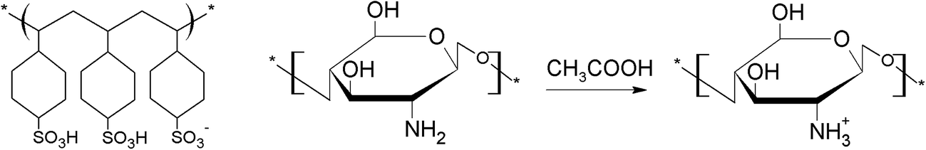 | ||
| Fig. 1 Chemical formula of PSS and CS. | ||
Fig. 2 shows the modification of cotton fabric using the ESA LbL process for the deposition of PSS and CSG. Briefly, the cotton fabric was soaked in PSS solution for 20 min at room temperature to get negatively charged and dried. After that, the positively charged CSG layer was deposited on PSS layer, reversing the charge polarity on the surface of fabric. Distilled water was used to rinse non-adsorbed CSG solution before drying modified fabric in oven. The number of times the deposition was carried out was 1, 3, 5 and 10, and the as-obtained cotton fabrics were denoted as PCSG1, PCSG3, PCSG5 and PCSG10, respectively. The untreated fabrics are considered as the control fabrics, which was 100% control fabric without any treatment.
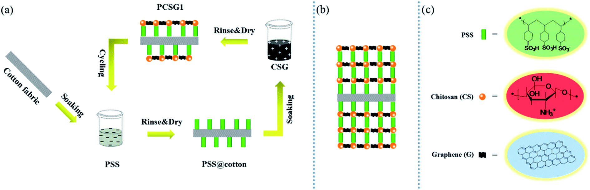 | ||
| Fig. 2 (a) Schematic diagram for the step-by-step growth of PSS and CSG via ESA process, resulting in (b) building structure of PSS/CSG on the cotton fabric surface, (c) representations of building blocks used in fabrication of PCSG fabrics. | ||
The combination mechanism between positive and negative electrolyte ions in above LbL self-assembly process has been detailed explained as follows.28 The cotton fabric surface is negatively charged after the PSS solution treatment. When the CSG layer is deposited, the cationic electrolyte group (–NH3+) of chitosan molecule chain with positive charge gets attached to the anionic electrolyte group (–SO3−) as shown in Fig. 3, leading to charge reversal on the fabric surface, which becomes positively charged. As described above, these two solutions with opposite charges were adsorbed alternately, resulting in multilayer structure on the fabric matrix.
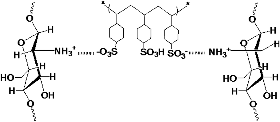 | ||
| Fig. 3 The combination mechanism between PSS and CS. | ||
2.3. Characterization
To derive more information of the structure and chemical composition of the PCSG fabric specimen, an X-ray photoelectron spectroscopic (XPS) measurement was carried out using a Kratos AXIS His spectrometer.The morphological structures of chitosan material, fabric samples were characterized using scanning electron microscopy (SEM, EHT = 3.0 kV, work distance = 8.0 mm, ZEISS-EVO18, Germany) and atomic force microscopy (AFM, SPM9700, Shimadzu, Japan). Further, surface potential was used to measure the polyelectrolyte distribution on the fabric surface by Malvern ZS90 (Britain Malvern Co.) at room temperature.
Air permeability of the control fabric and the PCSG fabrics were examinated using air permeability equipment (KES-F8-AP1). The mechanical properties of the PCSG fabrics as well as the control fabric were tested using INSTRON 5500R Universal Testing Machine (fabric specifications 100 mm × 33 mm, gauge length 100 mm, tensile speed 20 mm min−1).
2.4. Electrical conductivity test
The surface electrical conductivity of the PCSG fabric was measured according to,29 using a Rigol DM3068 digital multimeter analyzer. Testing voltage ranged within −15 to +15 V was applied and the corresponding I–V curve data was recorded every 0.5 V interval. The electrical resistance of the samples was measured 5 times in a standard atmosphere and the average values were noted.2.5. Electro-heating behavior test
The conductive samples were connected to a DC power source (KXN-305D, Shenzhen Zhaoxin Electronic Equipment Co., Ltd.) using conducting wires, (DC 1, 3, 5 and 7 V) (Fig. 4). The temperature was measured using an infrared thermometer (Shenzhen Jumaoyuan Science and Technology Co., Ltd.) at a interval 10 times per min.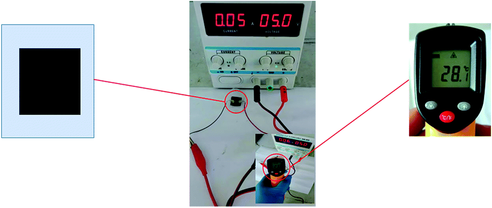 | ||
| Fig. 4 Schematic diagram of electro-heating measurement setup. | ||
2.6. Electromagnetic shielding effectiveness test
According to the standard method of ASTM D 4935-99, electromagnetic shielding test was carried out in the frequency range 30 MHz to 6 GHz using a circular coaxial transmission line holder. The reference and load samples of size 15 cm × 15 cm, were placed in the test setup. The scattering parameters (S-parameters) were obtained from the EMI SE test at room temperature (25 °C) and humidity (50% RH). The EMI SE value was expressed in dB and determined based on the measured S parameters as follows:| R = |S11|2, T = |S21|2, A = 1 − R − T |
| SEref (dB) = −10log(1 − R), SEabs (dB) = −10log(T/(1 − R)) |
| SEtotal = 10log(PI/PT) = SEref + SEabs |
2.7. Recycle performance test
According to the AATCC Test Method 61-2006, durability test of the PCSG fabrics was carried out. Specifically, the fabric specimen was laundered in 200 mL aqueous solution of an AATCC Standard Reference Detergent WOB (0.37%, w/w)30 using a standard color fastness laundering machine (Model SW-12AII, Wenzhou Darong Textile Instrument Co., Ltd., China). Electrical conductivity of the fabric were measured after 10 washings.3. Results and discussion
3.1. Microstructure and morphology of PCSG LbL fabrics
The SEM images of CS, CSG and the PCSG LbL cotton fabrics are shown in Fig. 5. It can be seen from Fig. 5a that the CS film exhibits good film-forming ability and homogeneous smooth surface, after doped with graphene nanosheet as shown in Fig. 5b, the morphology of CSG surface changed into wrinkle surfaces arising from the exist of graphene nanosheets. In addition, graphene nanosheets are well-dispersed in chitosan substrate and no aggregation occurs indicating that the overlapped graphene nanosheets could form well electrical network and good electrical conductivity.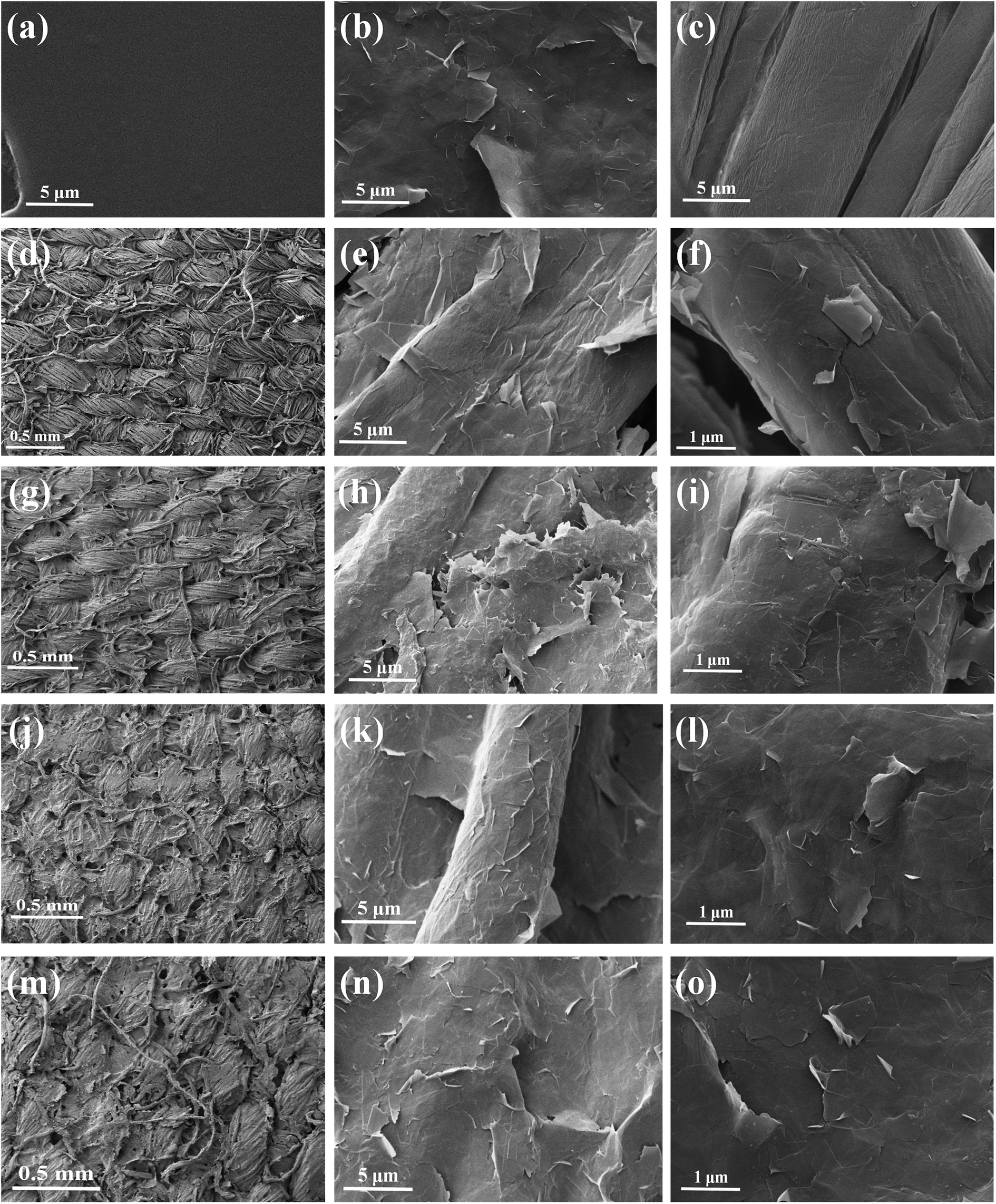 | ||
| Fig. 5 SEM images of (a) CS, (b) CSG, (c) control fabric, (d–f) PCSG1 fabric, (g–i) PCSG3 fabric, (j–l) PCSG5 fabric, (m–o) PCSG10 fabric under different magnifications. | ||
The morphological tendency of PCSG1–PCSG10 fabrics with the increasing cycles of self-assembled PSS and CSG monolayers are illustrated in Fig. 5d–o, respectively. Fig. 5c shows the control cotton fabric whose surface is clean and smooth with some typical longitudinal stripes. After one LbL cycling self-assembly process, the interlace structure of warping yarns and weft yarns in PCSG1 fabric can be visibly detected from Fig. 5d, enlarging to the higher magnification of single fibers in Fig. 5e, the surface of fiber can be partly coated with irregular graphene nanosheet, and the nanosheets are not entirely overlapped with each other. After 3–5 cycles LbL processes, PCSG3 and PCSG5 fabric could also exhibit clear warp and weft interlacing structure indicating the LbL process does not affect the basic texture of cotton fabric, furthermore, in Fig. 5k of PCSG5 fabric, the cotton fiber has been entirely coated with graphene nanosheet after five times assemblies, the smooth cylinder-shaped fiber implies the well dispersed of graphene nanosheet and well interaction between graphene nanosheets and cotton fiber. With continuing stacking LbL self-assembly to ten layers of PCSG10 fabric as shown in Fig. 10m–o, the interlaced fabric structure and fiber appearance are mostly invisible owing to the excessive stacking layers. In a word, LbL self-assembly process is a facile and tunable route to adjust the morphology of fiber substrate from different depositing cycles. Graphene nanosheets can be well-dispersed and interacted with fiber cotton fiber by electrostatic attraction between chitosan and PSS.
The morphological changes of the cotton fabrics resulting from PSS and CSG deposition are also scanned using the AFM technique. As seen in Fig. 6a, the dark red brown depressed part reveals the boundary between the microfibers of the control cotton fiber, which shows the typical parallel microstructure of natural cotton fiber. With respect to the control cotton fiber, smaller surface roughness obviously shows on the surface of the LbL fabrics modified with PSS, with thickness reduction from 285.4 nm to 236.8 nm (Fig. 6b). Fig. 6c shows the microfibril of cotton fibers that are completely sheathed with PSS/CSG layers with the apophysis and lamellar structure, indicating the components of PSS and CSG assembly multilayer film evenly concentrated on the fibers surface. Both of the SEM and AFM images demonstrated that the LbL films composed of PSS and CSG tightly covered the cotton fiber.
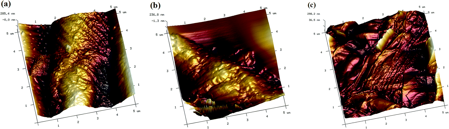 | ||
| Fig. 6 AFM images: (a) cotton fabric, (b) PSS fabric, (c) PCSG fabric. | ||
The XPS spectra of the cotton fabric, and PCSG1 fabric with the PSS monolayer as outside surface and PCSG1 fabric with the CSG monolayer as outside surface could help analyze the chemical composition of sample surface. The typical XPS wide scan spectrum of the control cotton fabric was shown in Fig. 7a, presenting all the standard photoelectron lines of elemental carbon and oxygen in cellulose. In the spectrum of the cotton fabric with PSS outside, only PSS with a small amount of elemental sulfur is detected, which indicated that a compact coating is formed on the fabric surface. As for cotton with CSG outside, elemental nitrogen (2.01 ± 0.06%) that existed as a trace element in chitosan is detected implying the chitosan film is formed on the outside surface of fibers. The detected atomic ratio of carbon could be as high as 86.79 ± 0.12% which is much higher than the other samples, arising from the exist of abundant graphene nanosheet.
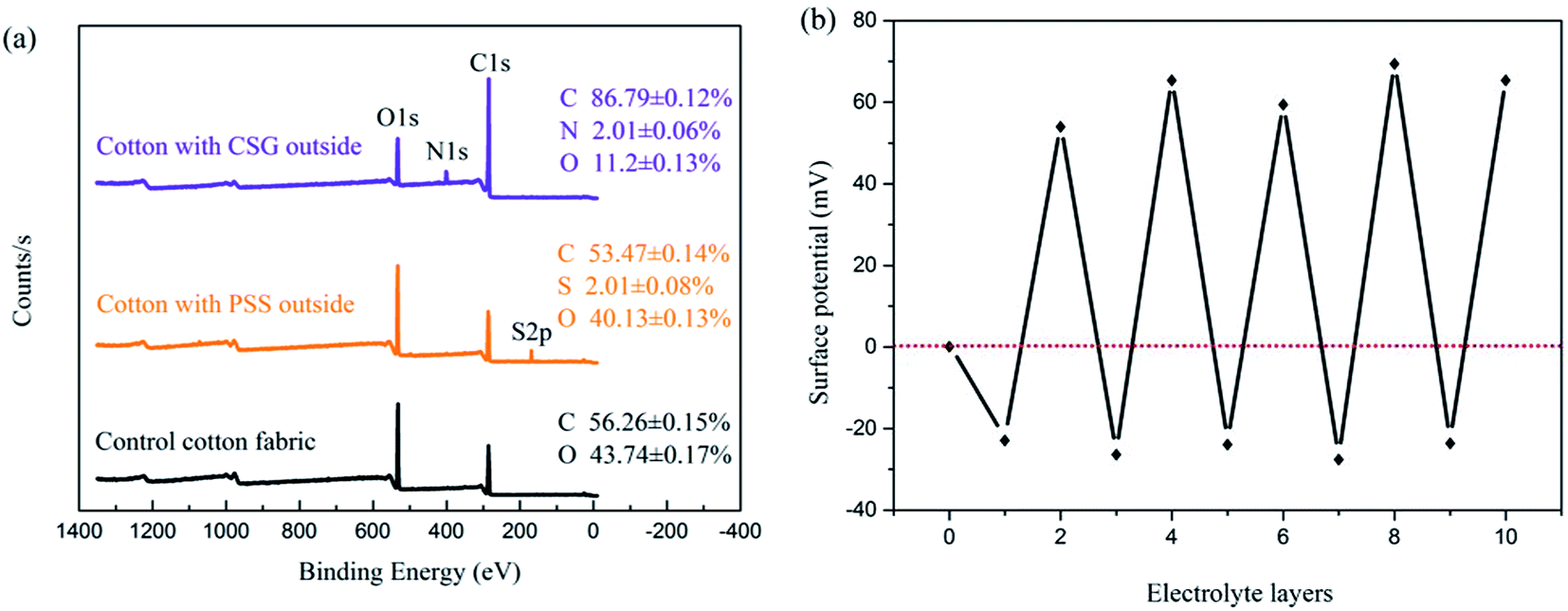 | ||
| Fig. 7 (a) The XPS spectra of the control fabric and cotton fabrics with PSS and CSG monolayer; (b) surface potential with the number of PSS/CSG layers. The odd layers (1, 3, 5, 7, and 9) correspond to PSS deposition and the even layers (2, 4, 6, 8, and 10) correspond to CSG adsorption. Layer 0 represents cotton fabric without layering. | ||
The surface charge depends on the layer-by-layer coating of polyelectrolytes. To understand the formation of each polyelectrolyte layer deposited on the cotton fabric, the surface potential experiment is performed. The variation of surface potential with the polyelectrolyte layer number for PSS/CSG coatings is shown in Fig. 7b. As is well known, the control fabric has a weak positive potential of +0.7 mV. With the PSS single layer having negative charge, the potential changes from +0.7 to −22.3 mV. The interface interaction between layer-by-layer is deemed as the key factor to influence the performance of PCSG fabrics, according to some ref. 31 and 32, the interface interaction of PCSG fabrics were investigated based on the electrolyte characteristic of polyelectrolyte layer.33,34 With the deposition of the positively charged CSG layer, the potential changes from −22.3 to +54.6 mV. Further deposition of the PSS and CSG layers alternatively, leads to oscillations of the potentials roughly between these two potentials of opposite signs. This indicates that a stepwise polyelectrolyte layer growth takes place during the fabrication of the PCSG samples.35
3.2. Air permeability, mechanical properties and Young's model
The results of air permeability (K) tests are listed in Table 1. Compared to the control fabric, the air permeability K of the treated fabric slightly decreases with increased number of deposited PCSG layers, as the multilayer composite film hindered the flow of air through the cotton substrate. It can be concluded that this attenuation has almost no effect on the breathable performance of the substrate, even with the K value of the PCSG10 reducing to 14.4%. Therefore, the breathable performance of the modified fabric has not changed much with the multilayer LBL composite films.| Samples | Air permeability (m (kPa s)−1) | |
|---|---|---|
| Mean | Standard deviation | |
| Control fabric | 3.19 | 0.009 |
| PCSG1 | 3.17 | 0.007 |
| PCSG3 | 3.11 | 0.011 |
| PCSG5 | 3.02 | 0.006 |
| PCSG10 | 2.73 | 0.008 |
The mechanical properties of the PCSG fabrics with various LbL layers as well as the control fabric were investigated by tensile tests at constant temperature and humidity conditions. A typical yield behavior could be observed on all samples with increasing stress during tension. The typical load-elongation curves are shown in Fig. 8a. Results showed that the addition of LbL PCSG layers did not significantly affect the tensile property of the cotton matrix. The tensile strength and elongation of PCSG10 fabric decreased marginally to 279 N and 14.2% from 322 and 15.5%, respectively, yielding was imperceptible, and the elongation at break decreased gradually. Fig. 8b shows Young's modulus of PCSG samples with increasing stacking LbL layers, and the value were 3.27, 3.25, 3.18, 3.12, and 3.01 GPa for PCSG1–PCSG10, respectively, and no more than 8% decrease occurs from control fabric to PCSG10 which exhibits a slight decreasing tendency with increasing LBL layers.
 | ||
| Fig. 8 (a) Representative load–elongation curves of the control fabric and PCSG samples with different LbL layers, (b) Young's modulus. | ||
The interface interaction (or load transfer efficiency) may be assumed to explain the limited performance improvement. The original soft cotton fabric structure becomes stiff after the PCSG treatment due to graphene deposition on the fabric substrate. When an external force is applied, the withstanding force of the PCSG fabrics gradually reduces owing to the structure deformation with increasing graphene loading weight, resulting in a decrease of fracture strength and the value of the Young's modulus. However, even in the case of PCSG10, the reduction of fracture strength is less than 13% as compared to the control fabric. In spite of the degradation of mechanical performance of the PCSG fabrics with increasing grapheme content, the mechanical properties are acceptable for commercial application.
3.3. EMI shielding effectiveness (SE)
Current vs. voltage (I–V) curves of the LbL fabric are shown in Fig. 9a. The I–V curves are measured within the bias voltage range −15 to 15 V at 0.5 V intervals which are perfectly symmetrical and linear for the LBL fabrics (PCSG 1, 3, 5 and 10) and the control fabric. The electrical conduction conforms to Ohm's law, as the slope of the I–V curves increasing with LBL layer deposition. This indicates that current amplification increases with increasing layer deposition and also of the graphene nanosheets. The surface resistance of the PCSG samples decreases with increasing layers of self-assembly. As shown in Fig. 9b, surface electrical conductivity increases rapidly from PCSG1 to PCSG10, and reaches a maximum value of 1.67 × 10³ S m−1. Based on the foregoing analysis of the morphology of the fabric shown in Fig. 5, uniformity of the graphene nanoplate dispersion on the fiber surface increases with higher mass of the graphene layers. Hence, the electrical conductivity of the fabric improves with greater uniformity of the graphene coating on the cotton fiber surface. After 10 times laundering, shown as Fig. 9b, the surface electrical conductivity decreased from 1.67 × 10³ S m−1 to 1.65 × 10³ S m−1 for PCSG10 fabric, and also slightly decreased for all other PCSG samples. The marginal reduction does not affect its electrical properties significantly, showing that grapheme tightly attached to the fiber surface during the LBL process.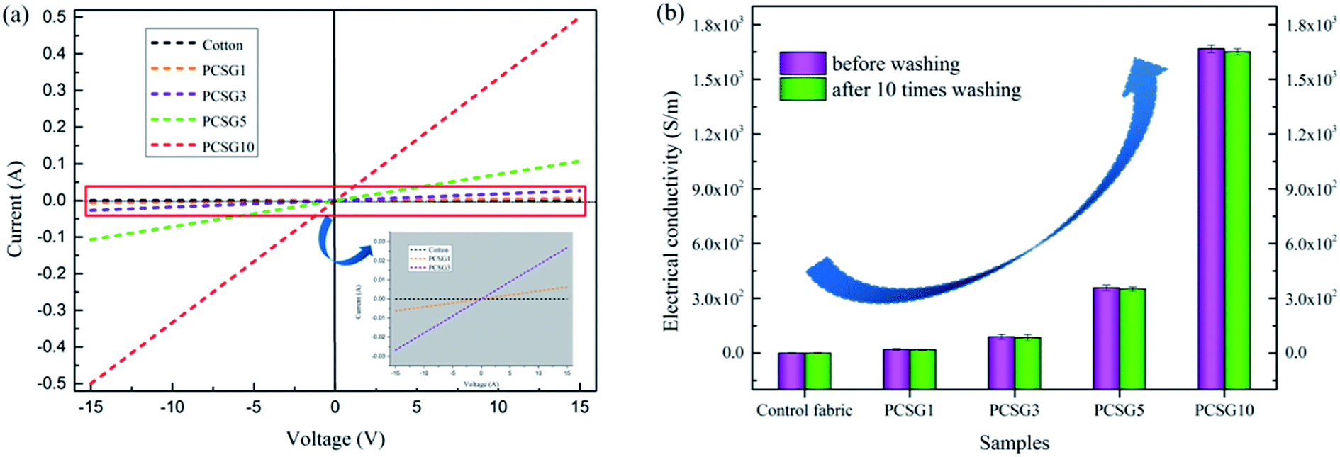 | ||
| Fig. 9 (a) Current vs. voltage curve, and (b) variation of surface electrical conductivity of PCSG fabrics and uncoated fabrics. | ||
Fig. 10 shows the EMI shielding effectiveness of PCSG fabrics (PCSG1, PCSG3, PCSG5, and PCSG10) tested within 30 MHz to 6 GHz frequency range. As expected, the control cotton fabric can not play the electromagnetic shielding effect. In contrast, PCSG fabrics with different LBL layers showed different EMI shielding effectiveness due to varying LbL layers. Fig. 10a shows the shielding efficiency curves as functions of electrical conductivity. As shown, excellent electrical conductivity is a prerequisite for excellent electromagnetic shielding (SE), which is consistent with the Schelkunoff theory.36 As the LBL layers increasing, the color of the samples turn from dark gray (PCSG1) and become deeper turning to thick black (PCSG3–PCSG10) as seen in Fig. 10a. As shown in Fig. 10b, the average SEtotal for single layer PCSG1 is ∼8.6 dB. This value is found to be low due to lower graphene loading as well as its lower conductivity (20 S m−1). The PCSG3 layer has an average SEtotal of ∼16.77 dB over the measured bands, with 89 S m−1 electrical conductivity, which is about two times as that of PCSG1. With increase in LBL layers, the average SEtotal of PCSG5 is found to be substantially improved, reaching ∼25.1 dB due to the increased electrical conductivity (357 S m−1), and an even higher value of ∼30.04 dB for PCSG10 sample with a 1667 S m−1 electrical conductivity over the entire measured bandwidth, far surpassing the target level of ∼20 dB required for commercial application as shown in Table 2. Compared with other carbon materials, the introduction of graphene can improve the EMI shielding performance of the cotton fabric, that is, layered graphene loading on cotton substrates can lead to substantial improvement in EMI shielding effectiveness. The SEA values of the PCSG fabrics (as shown in Fig. 10c) with increasing LbL layers are in the ranges of 1.1–6.4, 7.6–12.9, 12.7–19.4, 17.8–24.9 dB, respectively. The SER values of the PCSG fabrics (as shown in Fig. 10d) also exhibit the similar increasing tendency in the ranges of 0.4–2.1, 2.1–4.0, 4.3–6.8, 4.6–7.5 dB, respectively. Therefore, it is worth noting that the contribution of absorption to the EMI shielding is much larger than that of reflection, indicating the primary absorption characteristic of the PCSG fabrics towards the EM wave, which is consistent with the previous results.37
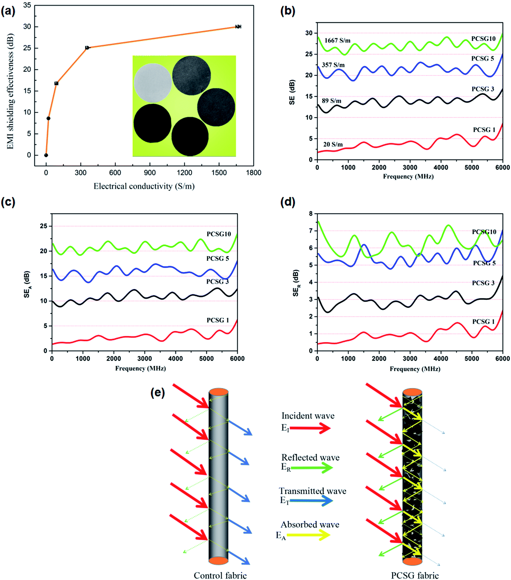 | ||
| Fig. 10 (a) EMI shielding effectiveness changes with electrical conductivity, (b) SEtotal of PCSG fabrics, (c) SEA of PCSG fabrics, (d) SER of PCSG fabrics and (e) contrast of shielding mechanism before and after LbL self-assembly. | ||
| No. | Substrates | Modification routes | Carbon-based materials | EMI SE (dB) | Reference |
|---|---|---|---|---|---|
| 1 | Cotton | Dip-drying process | MWCNTs | 9.0 | 42 |
| 2 | Vinylon | Blade coating method | Graphite nanosheets | 28.0 | 43 |
| 3 | Polyester | Pad-dry-cure method | Nano carbon black | 7.7 | 44 |
| 4 | Polyester | Plasma assisted dip-drying | NH2–MWCNTs | 18.2 | 45 |
| 5 | Cotton | Knife over roller coating | Carbon black | 31.39 | 46 |
| 6 | Nonwoven | Knife-over-roll coating | Carbon nanotube | 15–40 | 29 |
| 7 | Cotton | Layer-by-layer self-assembly | Graphene nanosheets | 30.04 | This work |
Previous studies have found that the shielding effect of electromagnetic shielding materials is mainly based on the reflection, absorption, and multiple-reflection of electromagnetic waves.38 In the case of EM being reflected, mobile charge carriers (electrons or holes) of the shielding materials interact with the incoming EM waves and weaken them.39 Shielding by absorption is due to interaction of the EM waves with electrical or magnetic dipoles of the shielding material. Internal reflections in the shielding materials with large surface areas lead to multiple reflections.
Fig. 10e shows the difference in the shielding mechanism before and after finishing by LbL, where, the line thickness represents the intensity of the wave. In the uncoated cotton fabrics, most of the incident waves penetrate the substrate, and reflection and multiple reflections are negligible, which indicate that there is almost no shielding effect in pure cotton fabrics. In this work, the electromagnetic wave attention mechanism of the PCSG fabrics can be generally elucidated based on two reasons. Fristly, ultrathin and flexible graphene nanosheets can entirely wrapped cotton fiber from the SEM images in Fig. 5, implying the conductive paths on the fiber surface have been well established, which leads to high-efficient microwave attenuation via the conversion of microwaves into heat.37 Secondly, graphene nanosheet with ultrathin, flexible and corrugated characteristics could increase the propagation paths for the EM waves in the wrapped layer of cotton fiber, and the corrugated graphene layers with oscillatory currents could accelerate the scattering of the EM waves to consume substantial EM wave energy. In addition, with the increasing cycles of LbL procedure, the PCSG fabric exhibited enhanced EMI SE performance which can be proved with increase mass ratio of graphene nanosheet and conductive paths. The fundamental principles for achieving high-performance EMI shielding materials is consistent with previous literatures.40,41
3.4. Electro – heating behavior
The electro – heating behavior of the PCSG fabrics with various LbL PCSG layers was investigated in the voltage range from 1 to 7 V and the temperature – time curves of the samples are shown in Fig. 11. Temperatures of the samples increased with application of electrical potential at time t > 0, and attained steady-state values at time ∼8 min, and decreased rapidly to room temperature values when the applied voltages were switched off at 25 min. Above phenomenon reveals that the electric heating behavior of the PCSG fabrics is closely related to the graphene content as well as the applied voltage. At a fixed applied voltage, the PCSG sample with more stacking layers reaches a higher steady-state temperature, because of its lower electrical resistance, and for a given PCSG sample, the steady-state temperature also increases with increasing applied voltages, which indicates performance controllability due to electrical heating. The Tmax values increased quadratically with the applied voltage, which is in accordance with the relationship of P = IV = V2/R (the electric power was converted to heat by the resistance heating or Joule heating process because of the graphene loading on fabrics). The attained Tmax was ∼134.0 °C for PCSG10 and ∼21.6, ∼27.0, ∼73.2 °C for PCSG 1, 3, 5 when the applied voltage was 7 V, which shows that higher graphene loading on the fabric substrate leads to better electric energy efficiency.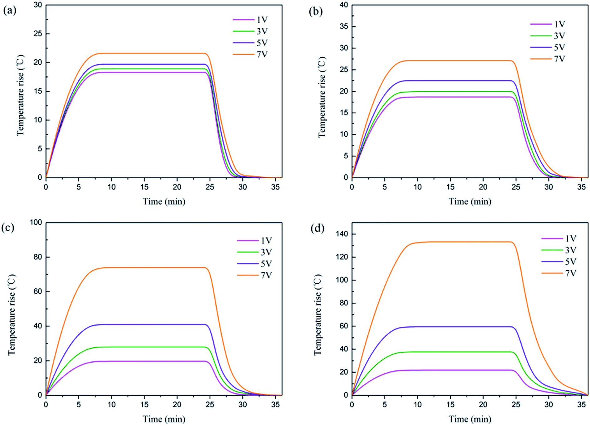 | ||
| Fig. 11 The time-dependent temperature profiles of (a) PCSG1, (b) PCSG3, (c) PCSG5, (d) PCSG10 fabric. | ||
Stability and recyclability are essential performances for the new generation of wearable electronics and devices. In order to satisfy these requirements, the influence of twisting deformations on electrical heating properties and temperature responses with the application of a series of stepwise voltage of the PCSGs were explored, for which, PCSG5 was selected as a representative.
Contrast test of the electric heating behavior of PCSG5 under the untwisted and twisted states was carried out at 7 V of voltage. As shown in Fig. 12a, the temperature – time curve during electric heating process remained consistent even though the composite plate was highly twisted by 540° deformation. Owing to the twisting deformation, electrical resistance increased marginally and the maximum temperature decreased slightly, indicating that the PCSGs could keep reliable and stable electrical heating performance under great mechanical deformation conditions. Recyclability of PCSGs as electric heating elements was measured by cyclic electric heating–cooling experiments, as shown in Fig. 12b. The applied voltage was incremented or decremented at 10 min intervals. The maximum temperature and temperature response rapidity of PCSG5 remained unchanged for each voltage in every cycle. It demonstrates that the electric heating performance of PCSGs was not affected by the thermal history of repeated electric heating cycles, and shows that the thermo-mechanical stability of PCSGs is excellent.
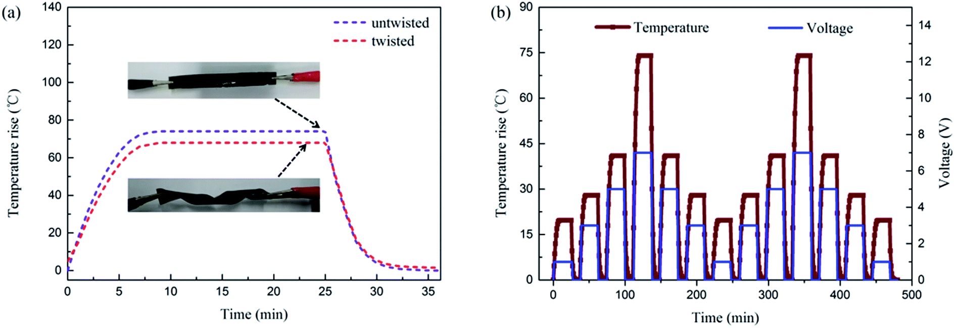 | ||
| Fig. 12 (a) Time-dependent temperature contrast of PCSG5 when untwisted and twisted at 7 V, and optical images in the illustration, (b) temperature responses of PCSG5 under a series of increasing voltage of 1, 3, 5, 7 V and decreasing voltage of 7, 5, 3, 1 V. | ||
4. Conclusion
Here in this paper, a durable ductile modified cotton fabric with remarkable electrical conductivity and EMI shielding properties is obtained through the deposition of graphene by a facile LbL electrostatic self-assembly technique. Studying the SEM images, a uniform and dense deposition of the graphene on cotton fabrics can be found achieved. A variety of tests reveal that the treated fabrics possess efficient physical and mechanical properties, electrical conductivity, EMI shielding performance and electro – heating behavior. The air permeability and tensile strength decrease slightly with the increasing self-assembled layers, yet the value of its commercial use has not been affected. Further, the electrical conductivity of the modified fabrics can be almost 10 orders of magnitude from 7.14 × 10⁻⁸ to 1.67 × 10³ S m−1, and the PCSG samples possess ultrastrong EMI shielding property even with very low graphene content. The SEtotal values basically increase with the increasing LbL layers, and can attain values of ∼25.1 dB in the PCSG5 sample, and even higher value of ∼30.04 dB for PCSG10, which meets requirements in commercial applications (the target level of ∼20 dB). The reason is mainly due to the enhanced microwave multiple reflections and scattering from the graphene network structure. Furthermore, the flexible PCSG10 fabric demonstrates remarkable electro-heating behavior, it reaches the steady-state maximum temperature (ΔTmax) 134 °C monotonically within 8 min while the ΔTmax = 21.6 °C of the control case under the same voltage 7 V, and exhibits favorable stability and recyclability. Overall, such a graphene-based fabric fabricated via facile LBL technique has proved the possibility in EMI shielding material.Conflicts of interest
There are no conflicts to declare.Acknowledgements
Financial support of this work was provided by Natural Science Foundation of China via grant No. 51672141 and 51306095, China Postdoctoral Science Foundation via grant No. 2014M561887 and 2015T80697, Shandong Province college science and technology plan project (J17KA030), Qingdao Postdoctoral Application Research Funded Project and Qingdao Application Basic Research Funded Project (15-9-1-41-JCH).References
- A. P. Singh, et al., Encapsulation of γ-Fe2O3 decorated reduced graphene oxide in polyaniline core-shell tubes as an exceptional tracker for electromagnetic environmental pollution, J. Mater. Chem. A, 2014, 2(10), 3581–3593 CAS.
- S. E. Lapinsky and A. C. Easty, Electromagnetic interference in critical care, J. Crit. Care, 2006, 21(3), 267–270 CrossRef PubMed.
- J. Joo and C. Y. Lee, High frequency electromagnetic interference shielding response of mixtures and multilayer films based on conducting polymers, J. Appl. Phys., 2000, 88(1), 513–518 CrossRef CAS.
- A. Zamanian and C. Hardiman, Electromagnetic radiation and human health: A review of sources and effects, High Frequency Electronics, 2005, 4(3), 16–26 Search PubMed.
- J. Voyer, P. Schulz and M. Schreiber, Electrically conductive flame sprayed aluminum coatings on textile substrates, J. Therm. Spray Technol., 2008, 17(5–6), 818–823 CrossRef CAS.
- K. B. Cheng, S. Ramakrishna and K. C. Lee, Electromagnetic shielding effectiveness of copper/glass fiber knitted fabric reinforced polypropylene composites, Composites, Part A, 2000, 31(10), 1039–1045 CrossRef.
- Y. Lu, S. Jiang and Y. Huang, Ultrasonic-assisted electroless deposition of Ag on PET fabric with low silver content for EMI shielding, Surf. Coat. Technol., 2010, 204(16), 2829–2833 CrossRef CAS.
- S. Q. Jiang, et al., Electroless nickel plating of polyester fiber, J. Appl. Polym. Sci., 2008, 108(4), 2630–2637 CrossRef CAS.
- C.-W. Lou, et al., Stainless steel/polyester woven fabrics and copper/polyester woven fabrics: Manufacturing techniques and electromagnetic shielding effectiveness, J. Ind. Text., 2016, 46(1), 214–236 CrossRef CAS.
- W.-L. Song, et al., Facile fabrication of ultrathin graphene papers for effective electromagnetic shielding, J. Mater. Chem. C, 2014, 2(25), 5057–5064 RSC.
- M.-S. Cao, et al., Ferroferric oxide/multiwalled carbon nanotube vs. polyaniline/ferroferric oxide/multiwalled carbon nanotube multiheterostructures for highly effective microwave absorption, ACS Appl. Mater. Interfaces, 2012, 4(12), 6949–6956 CAS.
- M.-S. Cao, et al., Ultrathin graphene: electrical properties and highly efficient electromagnetic interference shielding, J. Mater. Chem. C, 2015, 3(26), 6589–6599 RSC.
- B. Wen, et al., Reduced graphene oxides: light-weight and high-efficiency electromagnetic interference shielding at elevated temperatures, Adv. Mater., 2014, 26(21), 3484–3489 CrossRef CAS PubMed.
- B. Shen, W. Zhai and W. Zheng, Ultrathin flexible graphene film: an excellent thermal conducting material with efficient EMI shielding, Adv. Funct. Mater., 2014, 24(28), 4542–4548 CrossRef CAS.
- B. Shen, et al., Microcellular graphene foam for improved broadband electromagnetic interference shielding, Carbon, 2016, 102, 154–160 CrossRef CAS.
- Y. Li, et al., Ultrathin carbon foams for effective electromagnetic interference shielding, Carbon, 2016, 100, 375–385 CrossRef CAS.
- B. Shen, et al., Compressible graphene-coated polymer foams with ultralow density for adjustable electromagnetic interference (EMI) shielding, ACS Appl. Mater. Interfaces, 2016, 8(12), 8050–8057 CAS.
- W.-L. Song, et al., Magnetic and conductive graphene papers toward thin layers of effective electromagnetic shielding, J. Mater. Chem. A, 2015, 3(5), 2097–2107 CAS.
- W.-L. Song, et al., Flexible graphene/polymer composite films in sandwich structures for effective electromagnetic interference shielding, Carbon, 2014, 66, 67–76 CrossRef CAS.
- M. Shateri-Khalilabad and M. E. Yazdanshenas, Fabricating electroconductive cotton textiles using graphene, Carbohydr. Polym., 2013, 96(1), 190–195 CrossRef CAS PubMed.
- M. Tian, et al., Enhanced mechanical and thermal properties of regenerated cellulose/graphene composite fibers, Carbohydr. Polym., 2014, 111, 456–462 CrossRef CAS PubMed.
- L. Qu, et al., Functionalization of cotton fabric at low graphene nanoplate content for ultrastrong ultraviolet blocking, Carbon, 2014, 80, 565–574 CrossRef CAS.
- M. Tian, et al., Robust ultraviolet blocking cotton fabric modified with chitosan/graphene nanocomposites, Mater. Lett., 2015, 145, 340–343 CrossRef CAS.
- X. Hu, et al., Multifunctional cotton fabrics with graphene/polyurethane coatings with far-infrared emission, electrical conductivity, and ultraviolet-blocking properties, Carbon, 2015, 95, 625–633 CrossRef CAS.
- L. Karimi, et al., Optimizing the photocatalytic properties and the synergistic effects of graphene and nano titanium dioxide immobilized on cotton fabric, Appl. Surf. Sci., 2015, 332, 665–673 CrossRef CAS.
- T. Yang, et al., Tactile sensing system based on arrays of graphene woven microfabrics: electromechanical behavior and electronic skin application, ACS Nano, 2015, 9(11), 10867–10875 CrossRef CAS PubMed.
- X. Li, et al., Stretchable and highly sensitive graphene-on-polymer strain sensors, Sci. Rep., 2012, 2, 870 CrossRef PubMed.
- F. Fang, et al., Construction of intumescent flame retardant and antimicrobial coating on cotton fabric via layer-by-layer assembly technology, Surf. Coat. Technol., 2015, 276, 726–734 CrossRef CAS.
- R. R. Bonaldi, E. Siores and T. Shah, Characterization of electromagnetic shielding fabrics obtained from carbon nanotube composite coatings, Synth. Met., 2014, 187, 1–8 CrossRef CAS.
- B. Deng, et al., Laundering durability of superhydrophobic cotton fabric, Adv. Mater., 2010, 22(48), 5473–5477 CrossRef CAS PubMed.
- C. Hao-Sen, et al., Dynamic fracture toughness of piezoelectric ceramics, J. Am. Ceram. Soc., 2013, 96(7), 2036–2038 CrossRef.
- H.-S. Chen, et al., Anti-plane Yoffe-type crack in ferroelectric materials, Int. J. Fract., 2013, 179(1–2), 35–43 CrossRef.
- H.-S. Chen, et al., Propagation of a semi-infinite conducting crack in piezoelectric materials: Mode-I problem, J. Mech. Phys. Solids, 2014, 68, 77–92 CrossRef.
- H. Zhang, et al., Free vibration behaviors of carbon fiber reinforced lattice-core sandwich cylinder, Compos. Sci. Technol., 2014, 100, 26–33 CrossRef CAS.
- M. Chen, et al., Effect of Defect on the Compressive Response of Sandwich Structures with Carbon Fiber Pyramidal Truss Cores, Int. J. Appl. Mech. Eng., 2015, 7(1), 1550004 CrossRef.
- B. E. Keiser, Principles of electromagnetic compatibility, Artech House Inc, Dedham, Mass., 1979, vol. 341, p. 1979 Search PubMed.
- B. Wen, et al., Reduced graphene oxides: the thinnest and most lightweight materials with highly efficient microwave attenuation performances of the carbon world, Nanoscale, 2014, 6(11), 5754–5761 RSC.
- D. Chung, Electromagnetic interference shielding effectiveness of carbon materials, Carbon, 2001, 39(2), 279–285 CrossRef CAS.
- D. Chung, Materials for electromagnetic interference shielding, J. Mater. Eng. Perform., 2000, 9(3), 350–354 CrossRef CAS.
- M.-S. Cao, et al., The effects of temperature and frequency on the dielectric properties, electromagnetic interference shielding and microwave-absorption of short carbon fiber/silica composites, Carbon, 2010, 48(3), 788–796 CrossRef CAS.
- B. Wen, et al., Temperature dependent microwave attenuation behavior for carbon-nanotube/silica composites, Carbon, 2013, 65, 124–139 CrossRef CAS.
- L. Zou, et al., Superhydrophobization of cotton fabric with multiwalled carbon nanotubes for durable electromagnetic interference shielding, Fibers Polym., 2015, 16(10), 2158 CrossRef CAS.
- M.-M. Yu, et al., Novel flexible broadband microwave absorptive fabrics coated with graphite nanosheets/polyurethane nanocomposites, Prog. Nat. Sci.: Mater. Int., 2012, 22(4), 288–294 CrossRef.
- M. Simayee and M. Montazer, A protective polyester fabric with magnetic properties using mixture of carbonyl iron and nano carbon black along with aluminium sputtering, J. Ind. Text., 2016, 1528083716667261 Search PubMed.
- A. Haji, R. Semnani Rahbar and A. Mousavi Shoushtari, Improved microwave shielding behavior of carbon nanotube-coated PET fabric using plasma technology, Appl. Surf. Sci., 2014, 311, 593–601 CrossRef CAS.
- K. Gupta, S. Abbas and A. Abhyankar, Carbon black/polyurethane nanocomposite-coated fabric for microwave attenuation in X & Ku-band (8–18GHz) frequency range, J. Ind. Text., 2016, 46(2), 510–529 CrossRef.
Footnote |
| † These authors equally contributed to this work. |
| This journal is © The Royal Society of Chemistry 2017 |